ALTAI A175FD User manual

A175FD
Low-profile VESA MIS-F TV bracket
•For screens with VESA
MIS-F fixings
•Supports screens
of up to 65 kg
•For screens up to
1650 mm (65")
•Only 12mm from
screen to wall
•Pour écrans avec
fixations VESA MIS-F
•Supporte des écrans
pesant jusqu'à 65 kg
•Pour des écrans mesurant
jusqu'à 1650mm de diagonale
•Seulement 12mm entre
le mur et l'écran
Page 1

IMPORTANT
Installer and Users please note:
These instructions should be read carefully and left with the user of
the product for future reference.
BEFORE USE
You must inspect the product for any signs of damage. If the
product is damaged, DO NOT use it, and contact your supplier
immediately.
The following items should be included:
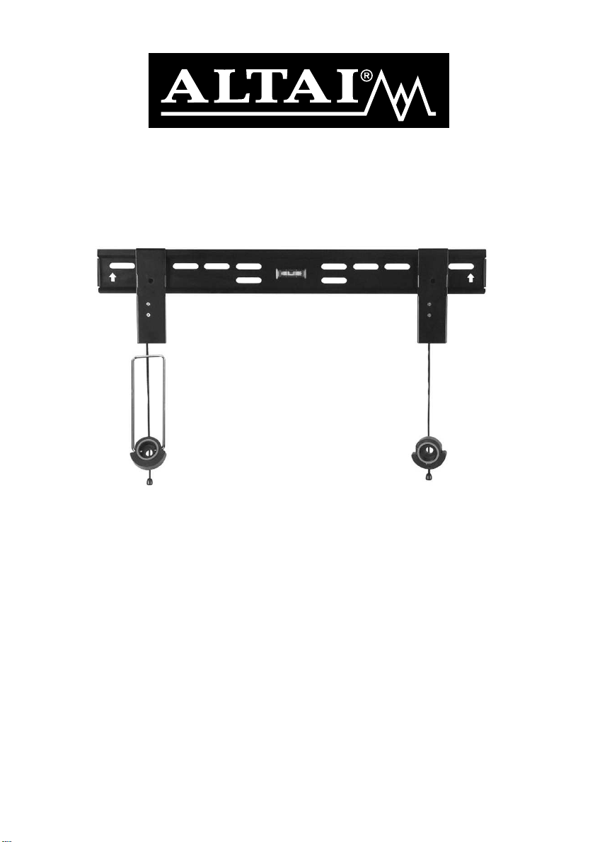
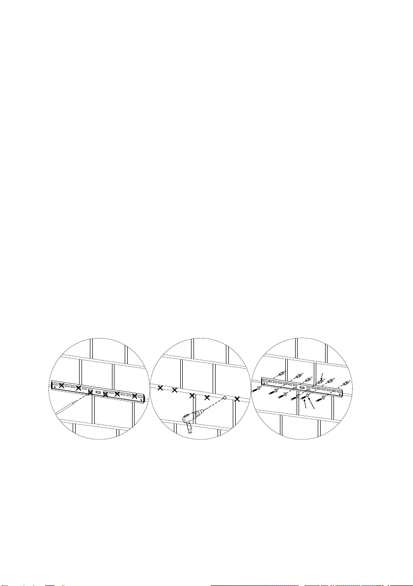
1 off horizontal part of bracket
2 off vertical part of bracket
[A] 6 off M8×50mm woodscrew
[B] 6 off Wall-plug
[C] 4 off M6 long spacer
[D] 10 off M6 washer
[E] 4 off M5 washer
[F] 4 off M5×16mm machine screw
[G] 4 off M6×16mm machine screw
[H] 4 off M8×16mm machine screw
[I] 4 off M5×30mm machine screw
[J] 4 off M6×30mm machine screw
[K] 4 off M8×30mm machine screw
[L] 4 off M5 shakeproof washer
[M] 4 off M6 shakeproof washer
[N] 4 off M8 shakeproof washer
PRODUCT SAFETY
•Severe personal injury or property damage can result from
improper installation or assembly of this product.
•Before lifting heavy objects, a risk assessment should be carried
out according to the Manual Handling Operations Regulations
1992 and any other appropriate Health and Safety Legislation.
•If you do not understand the instructions or have any concerns or
questions contact a qualified craftsman, or telephone the help line
on the number shown on the back page of this manual.
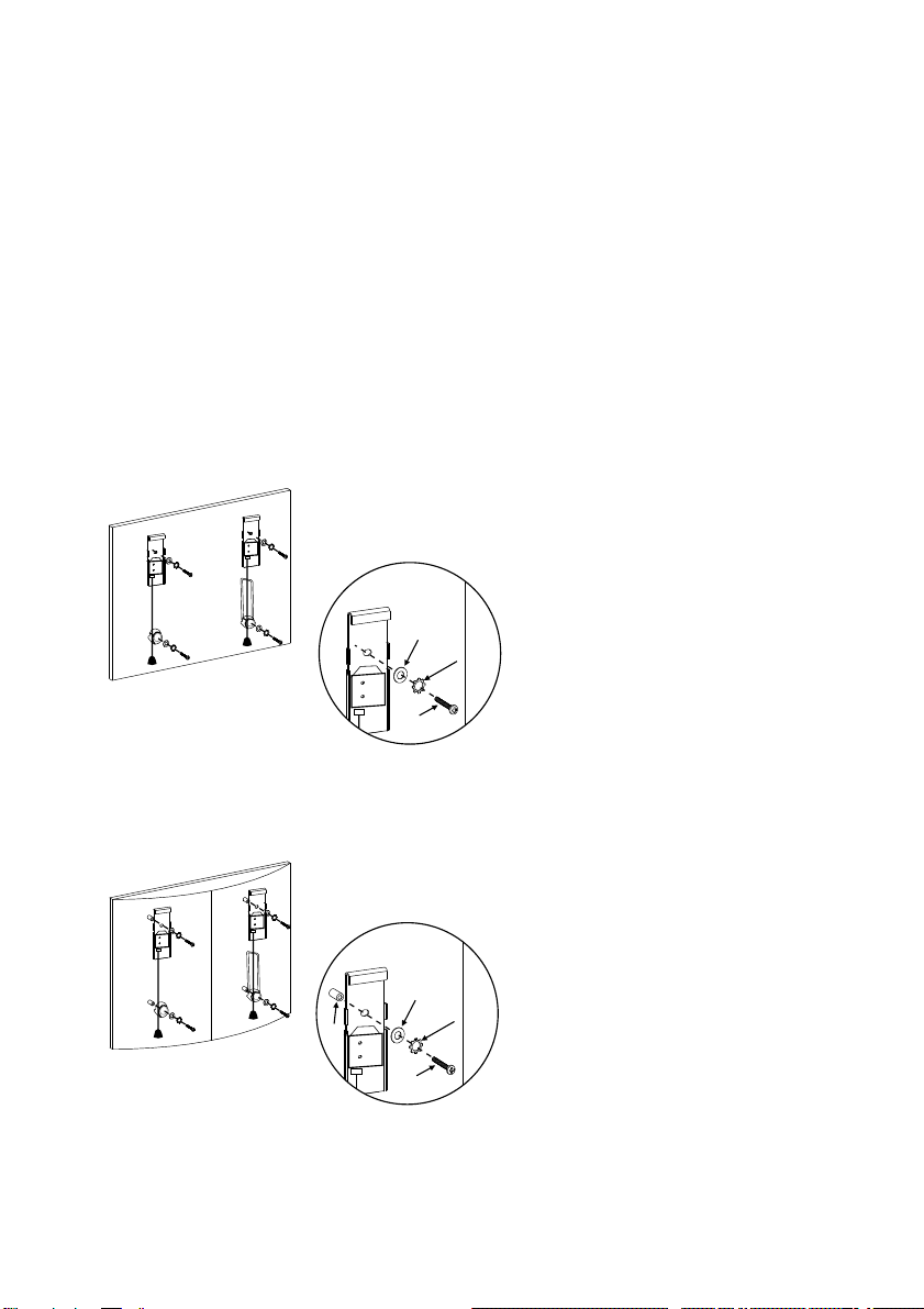
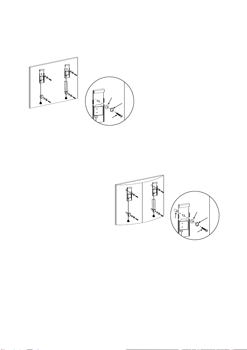
•This product is designed to attach to a solid vertical wall
Page 2

constructed of masonry or timber studding clad in plasterboard.
•Before commencing work, a risk assessment must be carried out,
to confirm that the wall can support 3 times the weight of the
screen and all its accessories.
•Do not use this product for anything other than its intended
purpose
•Electrovision accepts no responsibility for damage to the wall nor
the appliance attached to the bracket, nor any consequential
damage or injury caused by improper installation, improper use,
overloading or unauthorised modification of the product.
INSTALLATION
1a. If the screen has a flat back, attach the vertical parts of the
bracket to the mounting
holes in the screen using the
16 mm machine screws,
plain washers and
shakeproof washers as
shown. Check that the
screws used have the
correct threads to fit properly
into the female threads on
the screen. Do not drill into
the back of the screen.
[F/G/H]
[D/E]
[L/M/N]
1b. If the screen has a curved back, attach the vertical parts of the
bracket to the mounting holes in the screen using the 16 mm
machine screws, plain
washers and shakeproof
washers, inserting the
spacer [C] between the
bracket and the back of the
screen. Check that the
screws used have the
correct threads to fit properly
into the female threads on
the screen. Do not drill into
the back of the screen.
[ C ]
[I/J/K]
[D/E]
[L/M/N]
Page 3

2. Note the positon of the vertical parts of the bracket on the
screen, and determine the position where the horizontal part of the
bracket has to attach to the wall.
3a. For a plasterboard and timber-studding wall, determine the
positions of the timber studding, and attach the horizontal part of
the bracket to the wall using the M8×50 mm woodscrews and plain
washers.
Use the built-in spirit-level to ensure that the bracket is level.
Ensure that the screws go into the timber studding, not just into the
plasterboard. Ensure that the bracket is fastened to at least two
studs.
DO NOT use plasterboard fixings - they will not support the weight
of the screen.
[D][A]
[B]
3b. For a masnory wall, mark the positions of the fixing holes as
shown. Use the built-in spirit-level to ensure that the bracket is
level.
Drill with a 10 mm masonry drill and fit the wall plugs.
Attach the horizontal part of the bracket to the wall using the M8×
50 mm woodscrews and plain washers as shown.
Page 4

4. Align the vertical parts of the bracket (on
the back of the screen) with the horizontal
part (attached to the wall).
5. Pull the string to relase the catch
and engage the two parts of the
bracket. Release the string to
engage the catch which secures the
bracket in place.
TO REMOVE THE SCREEN FROM THE BRACKET
Pull the string to release the catch, then lift the screen off the
horizontal part of the bracket.
Page 5

TECHNICAL SPECIFICATION
VESA fitting: MIS-F
Maximum screen size :1270 mm (50")
Maximum Weight: 50 kg
SERVICE WARRANTY
Electrovision guarantees the product free from defects in materials
and workmanship for a period of twelve months.
Should this unit be operated under conditions other than those
recommended, or any attempts made to service or modify the unit,
then the warranty will be rendered void.
The product you buy may sometimes differ slightly from
illustrations. This warranty is in addition to, and does not affect,
your statutory rights.
If you have any problems with this product, please call our Help
Desk on (0845) 459 4816.
Electrovision Ltd.,
Lancots Lane,
Sutton,
St. Helens,
Merseyside.
WA9 3EX
website: www.electrovision.co.uk
Page 6

IMPORTANT
Installateurs et Utilisateurs, veuillez noter:
Vous devez lire cette notice attentivement et la conserver
pour une éventuelle future consultation.
AVANT UTILISATION
Vous devez contrôler que le produit ne présente aucun
dommage. Si le produit est endommagé, NE l'utilisez PAS, et
contactez immédiatement votre revendeur.
L'emballage contient les pièces suivantes :
1 partie de support horizontale
2 parties de support verticales
[A] 6 vis à bois M8x50mm
[B] 6 chevilles murales
[C] 4 entretoises longues M6
[D] 10 rondelles M6
[E] 4 rondelles M5
[F] 4 vis M5x16mm
[G] 4 vis M6x16mm
[H] 4 vis M8x16mm
[I] 4 vis M5x30mm
[J] 4 vis M6x30mm
[K] 4 vis M8x30mm
[L] 4 rondelles éventail M5
[M] 4 rondelles éventail M6
[N] 4 rondelles éventail M8
Page 7

CONSIGNES DE SECURITE
•Des blessures graves ou des dommages matériels
importants peuvent résulter d'une installation ou d'un
assemblage impropres de ce produit.
•Avant de soulever des objets lourds, une estimation des
risques doit être effectuée conformément au Règlement sur
la manutention manuelle et toute autre législation sur la
Santé et la Sécurité.
•Si vous ne comprenez pas ces instructions ou si vous avez
des questions ou préoccupations, contactez un artisan
qualifié ou téléphonez au numéro de téléphone figurant à la
fin de cette notice.
•Ce produit est prévu pour être fixé sur un mur vertical solide
construit en maçonnerie ou en bois revêtu de plaques de
plâtre.
•Avant de commencer à travailler, une évaluation des
risques doit être effectuée, pour confirmer que le mur peut
supporter 3 fois le poids de l'écran et de tous ses
accessoires.
•N'utilisez pas le produit pour autre chose que pour
l'utilisation à laquelle il est destiné.
•Electrovision décline toute responsabilité en cas de
dommages sur le mur, de dommages sur l'appareil fixé sur le
support, en cas de dommages ou de blessures indirects
causés par une installation ou une utilisation impropres,une
surcharge ou une modification non autorisée sur le produit.
Page 8

INSTALLATION
1a. Si l'arrière de l'écran
est plat, fixez les parties
verticales du support sur
les trous de montage de
l'écran en utilisant les vis
16 mm, les rondelles
simples et les rondelles
éventail comme indiqué
ci-contre. Vérifiez que le
diamètre des vis que vous
utilisez correspond bien
aux trous situés à l'arrière
de votre écran. Ne percez
pas l'arrière de votre écran de télévision.
[F/G/H]
[D/E]
[L/M/N]
1b. Si l'arrière de l'écran
est courbé, fixez les
parties verticales du
support sur les trous de
montage de l'écran en
utilisant les vis 16 mm, les
rondelles simples et les
rondelles éventail, en
insérant l'entretoise [C]
entre le support et l'arrière
de l'écran. Vérifiez que le
diamètre des vis que vous utilisez correspond bien aux trous
situés à l'arrière de votre écran. Ne percez pas l'arrière de
votre écran de télévision.
[ C ]
[I/J/K]
[D/E]
[L/M/N]
2. Notez la position des parties verticales du support sur
l'écran et déterminez la position où la partie horizontale du
support doit être fixée au mur.
Page 9

3a. Pour un mur en placoplâtre ou en bois recouvert de
plaques de plâtre, déterminez la position des poutres en bois
et fixez la partie horizontale du support sur le mur en utilisant
des vis à vis M8 50 mm et des rondelles simples.×
Utilisez le niveau à bulle intégré pour vérifiez que le support
est à niveau. Vérifiez que les vis rentrent dans les poutres en
bois et non pas seulement dans le placoplâtre. Vérifiez que
le support est fixé sur au moins 2 poutres.
N'UTILISEZ PAS de fixations pour le placoplâtre: elles ne
supporteraient pas le poids de l'écran.
3b. Pour un mur en maçonnerie, marquez les positions des
trous de fixation comme indiqué ci-contre. Utilisez le niveau à
bulle intégré pour vérifiez que le support est à niveau.
Percez avec un foret à maçonnerie de 10 mm et accrochez
les chevilles murales.
Fixez la partie horizontale du support sur le mur en utilisant
les vis à bois M8×50 mm et les rondelles simples comme
indiqué ci-contre.
[D][A]
[B]
Page 10

4. Alignez les parties verticales du
support (au dos de l'écran) avec la
partie horizontale (fixée au mur).
5. Tirez sur la ficelle pour libérer
l'emprise et engager les deux
parties du support. Relâcher la
ficelle pour enclencher l'attache
qui sécurise le support en place.
POUR ENLEVER L'ECRAN DU SUPPORT
Tirez sur la ficelle pour libérer l'emprise puis soulevez l'écran
de la partie horizontale du support.
Page 11

CARACTERISTIQUES TECHNIQUES
VESA : MIS-F
Taille maximum de l'écran (diagonale): 1270 mm
Poids maximum : 50 kg
GARANTIE
Electrovision garantit ce produit contre tout défaut de
matériaux ou de fabrication pendant douze mois. Si cet
produit est utilisé dans des conditions inappropriées, autres
que celles indiquées dans cette notice, si vous tentez de
modifier ou réparer ce produit, la garantie est annulée.
Le produit que vous achetez peut être légèrement différent
de l'illustration. Cette garantie est en sus, et n'affecte pas vos
droits statutaires.
En cas de problème sur ce produit, vous pouvez nous
contacter au 01.30.34.48.60
ALTAI EUROPE LTD
Z.A. Du Bel Air
17 D rue de Creil
95340 BERNES-SUR-Oise
Page 12
Table of contents
Languages:
Other ALTAI Wireless Access Point manuals
Popular Wireless Access Point manuals by other brands

Ubiquiti
Ubiquiti UAP-IW-HD quick start guide

Pakedge
Pakedge WX-1 quick start guide

Edimax
Edimax EW-7303HPn V2 Connection guide

DIGITAL YACHT
DIGITAL YACHT WL400 Technical notes

Ruijie
Ruijie RG-AP840-I (V2) Hardware installation and reference guide

SMC Networks
SMC Networks EZ Connect Turbo SMC2455W user guide