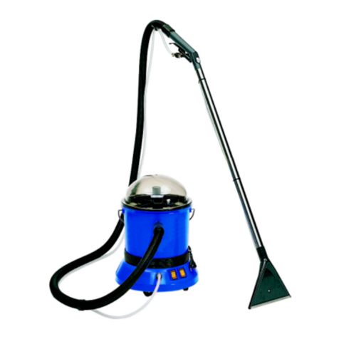
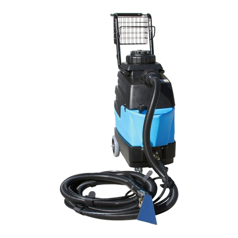
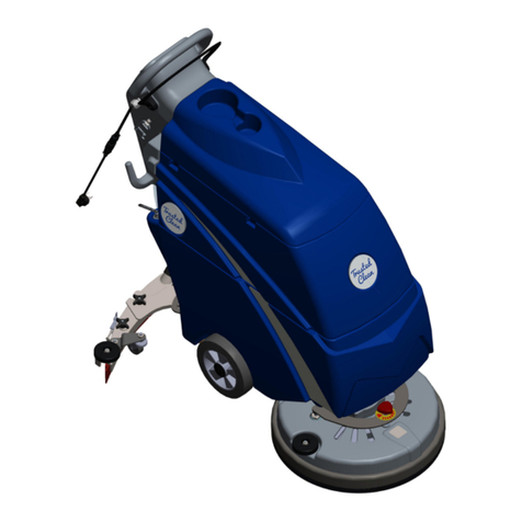
Alto Clarke IMAGE 14 User manual

Operator's
Manual
READ THIS BOOK
Thisbookhasimportantinformationfortheuseandsafeoperationofthismachine. Failuretoreadthis
book prior to operating or attempting any service or maintenance procedure to your Clarke machine
could result in injury to you or to other personnel; damage to the machine or to other property could
occur as well. You must have training in the operation of this machine before using it. If you or your
operator(s) cannot read English, have this manual explained fully before attempting to operate this
machine.
Si Ud.osusoperadoresnopuedenleerelInglés,sehaganexplicarestemanualcompletamenteantes
de tratar el manejo o servicio de esta máquina.
All directions given in this book are as seen from the operator’s position at the rear of the machine.
For new books write to: Clarke®, 2100 Highway 265, Springdale, Arkansas 72764.
Form No. 70088A 9/02 Clarke®Printed in the U.S.A.
IMAGE 14
120V
Division of

Page 2 Clarke®Operator's Manual - Image 14
TableofContents
OperatorSafety Instructions ............................................................................................................ 3
Introduction & Machine Specifications ............................................................................................. 5
Instructions - Power Supply 120Volt ................................................................................................ 6
MachineControls ............................................................................................................................. 7
HowTo Preparethe Machinefor Operation....................................................................................... 7
HowtoClean Carpet ........................................................................................................................ 8
OPERATOR'SMAINTENANCE:
How to Empty the RecoveryTank .............................................................................................. 9
How to Empty the SolutionTank ................................................................................................ 9
How to Attach the Auxiliary FloorTool........................................................................................ 10
After Each Use of the Machine.................................................................................................. 10
Howto PreventDamagefrom FreezingTemperatures ................................................................ 11
Spray Bar Nozzle ...................................................................................................................... 11
SECTION II Parts and Service Manual
AUTHORIZEDPERSONNELMAINTENANCE
To Access Pump/Brush Motor ................................................................................................... 14
BrushDrive BeltReplacement................................................................................................... 14
Maintenanceof theVacuumMotor............................................................................................. 14
Brushmaintenance.................................................................................................................... 14
Howto Correct Problemsin theMachine ......................................................................................... 15
Final Assembly Drawing & Parts List Image 14................................................................................ 16
Handle Assembly Drawings & Parts List .......................................................................................... 17
RecoveryTank Assembly Drawing & Parts List ................................................................................ 18
SolutionTank Assembly Drawing & Parts List .................................................................................. 19
Brush/Pump Assembly Drawing & Parts List ................................................................................... 20
Main Frame Assembly Drawing & Parts List ................................................................................... 21
Pump Drawing & Parts List .............................................................................................................. 22
ConnectionDiagram120Volts.......................................................................................................... 23
Electrical Schematic 120 Volts........................................................................................................ 24
AuthenticClarke Products ............................................................................................................... 25

Clarke®Operator's Manual - Image 14 Page 3
IMPORTANTSAFETYINSTRUCTIONS
WARNING AVERTISSEMENT ADVERTENCIA
DANGER: FailuretoreadandobserveallDANGERstatementscouldresultinsevere
bodilyinjuryordeath. ReadandobserveallDANGERstatementsfoundinyour
Owner'sManualandonyourmachine.
WARNING: FailuretoreadandobserveallWARNINGstatementscouldresultininjuryto
youortootherpersonnel;propertydamagecouldoccuraswell. Readand
observeallWARNINGstatementsfoundinyourOwner'sManualandonyour
machine.
CAUTION: FailuretoreadandobserveallCAUTIONstatementscouldresultindamageto
themachineortootherproperty. ReadandobserveallCAUTIONstatements
foundinyourOwner'sManualandonyourmachine.
WARNING: To reducethe risk of fire, electric shock, or injury:
1. Donotleaveapplianceunattendedwhenpluggedin. Unplugfromoutletwhennotin
useandbeforeservicing.
2. Toreducetheriskofelectricshockuseindoorsonly.
3. Do notallowto beusedas atoy. Closeattention is necessarywhenused byornear
children.
4. Useonlyasdescribedinthemanual. Useonlymanufacturer'srecommendedattach-
ments.
5. Do notuse withdamagedcord orplug. If appliance isnot workingasit should,has
beendropped,damaged,leftoutdoors,ordroppedintowater,returnittoaservice
center.
6. Donotpullor carrybycord,use cordasahandle, closeadooron cord,orpullcord
aroundsharpedgesorcorners. Donotrunapplianceovercord. Keepcordawayfrom
heatedsurfaces.
7. Do not unplug by pulling on cord. To unplug, grasp the plug, not the cord.
8. Donothandleplugorappliancewithwethands.
9. Do notput anyobjectinto openings. Donot usewithany openingblocked; keep freeof
dust,lint,hair andanythingthat may reduceairflow.
10. Keephair,looseclothing,fingers,andallpartsofbodyawayfromopeningsandmoving
parts.
11. Donotpickupanythingthatisburningorsmoking,suchascigarettes,matches,orhot
ashes.
12. Do notuse withoutfilters inplace.
13. Turnoffallcontrolsbeforeunplugging.
14. Useextracarewhencleaningonstairs.
15. Donotusetopickupflammableorcombustibleliquidssuchasgasolineoruseinareas
wheretheymaybepresent.
16. Connecttoproperlygroundedoutlet. See"GroundingInstructions".
SAVETHESEINSTRUCTIONS

Page 4 Clarke®Operator's Manual - Image 14
IMPORTANTESMESURESDESECURITE
AVERTISSEMENT:Pourréduirelesrisquesd'incendie,dechocélectriqueou
de blessure:
1. Nepaslaisserl'appareilsanssurveillancelorsqu'ilestbranché. Débrancherlorsque
l'appareiln'estpasutiliséetavantl'entretien.
2. Pourréduirelesrisquesdechocélectrique,utiliseràl'intérieurseulement.
3. Nepaspermettreauxenfantsdejoueravecl'appareil. Uneattentionparticuliéreest
4. N'utiliserqueconformémentàcettenoticeaveclesaccessoiresrecommandésparle
fabricant.
5. Nepasutilisersilecordonoulaficheestendommagé. Retournerl'appareilàunatelier
deréparations'ilnefonctionnepasbien,s'ilesttombéous'ilaétéendommagé,oubliéà
l'extérieurouimmergé.
6. Nepastirersouleveroutraînerl'appareilparlecordon. Nepasutiliserlecordoncomme
unepoignée,lecoincerdansl'embrasured'uneporteoul'appuyercontredesarêtesvives
oudescoins. Nepasfaire roulerl'appareilsurlecordon. Garderlecordonàl'écartdes
surfaceschaudes.
7. Ne pasdébrancherentirant surlecordon. Tirerplutôt lafiche.
8. Nepastoucherlaficheoul'appareillorsquevosmainssonthumides.
9. N'inséreraucunobjetdanslesouvertures. Nepasutiliserl'appareillorsqu'uneouverture
estbloquée. S'assurerquedelapoussière,delapeluche,descheveuxoud'autres
matièresneréduisentpasledébitd'air.
10. Maintenirlescheveux,lesvêtementsamples,lesdoigtsettouteslespartiesducorpsà
l'écartdesouverturesetdespiècesmobiles.
11. Nepasaspirerdematièresencombustionouquidégagentdelafumée,commedes
cigarettes,desallumettesoudescendreschaudes.
12. Nepasutiliserl'appareil sile sacà poussièreou lefiltre n'estpasenplace.
13. MettretouteslescommandesàlapositionARRETavantdedébrancherl'appareil.
14. Userdeprudencelorsdunettoyagedesescaliers.
15. Nepasaspirerdesliquidesinflammablesoucombustibles,commedel'essence,etne
pasfairefonctionnerdansdesendroitsoùpeuventsetrouverdetelsliquides.
16. "Nebrancherqu'àuneprisedecourantavecmiseàlaterre. Voirlesinstructionsvisant
lamise à laterre."
CONSERVERCESINSTRUCTIONS

Clarke®Operator's Manual - Image 14 Page 5
DANGER: Machinescancauseanexplosionwhenoperatednearflammablematerialsandvapors. Do
not use this machine with or near fuels, grain dust, solvents, thinners, or other flammable
materials.
WARNING: You must have training in the operation of this machine before using it. READ THE
INSTRUCTIONBOOKFIRST.
WARNING: Anyalterationsormodificationsofthismachinecouldresultindamagetothemachineorinjury
to the operator or other bystanders. Alterations or modifications not authorized by the
manufacturervoids any and all warrantiesand liabilities.
WARNING: Do not use this machine as a step or furniture. Injury could occur to the operator.
WARNING: To avoid serious injury, use proper lifting procedures when lifting the machine.
WARNING: Makesurethatallthelabels,decals,warnings,cautionsandinstructionsarereadable. Replace
them when necessary by ordering them from Clarke.
WARNING: Do not use water that is hotter than 140°F.
WARNING: Improperdischargeofwaste watermaydamagetheenvironmentand beillegal. TheUnited
States Environmental Protection Agency has established certain regulations regarding
discharge of waste water. Also, city and state regulation regarding this discharge may be in
effect in your area. Understand and follow the regulations in your area. Be aware of the
environmental hazards of chemicals that you dispose.
Introduction and Machine Specifications
TheImage 14 isan extractorforcleaning carpet. Themachineapplies cleaning solutionto the carpetandremoves
dirtysolution andsoil fromthe carpet. TheImage 14is equipped witha powerbrush. Theextractorhascontrols to
startthe solutionpump,and vacuummotor. Thismachineis intended forcommercialuse.
Specifications: Image 14
120V
Model 04120A
Electrical 120 V. 50/60 Hz
Solution Pump 45 PSI Bypass
Power Cable 35' 14/3-wire
Spray Jets 1 Quarter Turn Q.C.
Solution Tank Capacit 4 Gallon
Recovery Tank 4 Gallon
Waterlift/CFM 82"/97
Vacuum Tangential discharge,
1.25 HP, 2 stage
Brush Size 3½" x 11"
Brush Motor Size 1/8 HP
Dimensions 31½" x 37" x 14"
Weight 55 lbs.
ShippingWeight 65 lbs.
Control Switch
Recovery Tank
Recovery Tank Handle
Vacuum Hose
SolutionTank
Recovery Tool
Self Adjusting Brush
Locking
Handle
AuxiliaryConnection

Page 6 Clarke®Operator's Manual - Image 14
120 VOLT, 50/60 CYCLE MACHINES
GROUNDING INSTRUCTIONS
This product must be grounded. If it should malfunction or
breakdown, grounding provides a path of least resistance
for electric current to reduce the risk of electric shock. This
product is equipped with a cord having an equipment-
grounding conductor and grounding plug. The plug must be
inserted into an appropriate outlet that is properly installed
and grounded in accordance with all local codes and
ordinances.
WARNING: Improper connection of the
equipment-grounding conductor can result in a risk of elec-
tric shock. Check with a qualified electrician or service
person if you are in doubt as to whether the outlet is prop-
erly grounded. Do not modify the plug provided with the
product - if it will not fit the outlet, have a proper outlet in-
stalled by a qualified electrician.
This product is for use on a nominal 120 volt circuit and has
a grounding attachment plug that looks like the plug
illustrated in Fig. 1. Make sure that the product is connected
to an outlet having the same configuration as the plug. No
adaptor should be used with this product.
For maximum protection against electric shock, use a circuit
that is protected by a ground fault circuit interrupter. The
green (or green and yellow) conductor in the cord is the
ground wire. Never connect this wire to any terminal other
than the ground terminal.
WARNING: To prevent possible electric shock, pro-
tect the machine from rain. Keep the
machine in a dry building.
WARNING: To prevent possible electric shock, al-
waysuse a3-wire electrical system con-
nected to the electrical ground. For
maximum protection against electrical
shock, use a circuit that is protected by
a ground fault circuit interrupter. Con-
sult your electrical contractor.
WARNING: Do not cut, remove or break the ground
pin. If the outlet does not fit the plug,
consult your electrical contractor.
WARNING: Have worn, cut, or damaged cords and
plugs replaced by an authorized service
person.
EXTENSION CORDS
Use only an approved extension cord with three conductors, a
plug with three terminals, and a connector body with three
holes. The machine has a power cord with wire size 14 AWG
(AWG means American Wire Gauge).
WARNING: If you use an extension cord, use an
extension cord with minimum wire
size 14 AWG. Do not use an exten-
sion cord longer than 50 feet. Do
not join two extension cords.
Figure 1
Grounded
Outlet
Grounded
OutletBox
Grounding
Pin

Clarke®Operator's Manual - Image 14 Page 7
HOW TO PREPARE THE MACHINE FOR OPERATION
THECONTROLS
The Vacuum/Accessory/Pump Switch
This switch is located on the handle. To turn the
vacuum motor on, place the switch in the middle
position. To turn pump, brush, and vacuum motor on,
place the switch in bottom position. (Figure 2, #1)
The Vacuum Hose Connector
The vacuum hose connector is on the right hand rear
of the machine. (Figure 2, #2)
The Solution Hose Connector
The solution hose connector is located on the bottom
center of the machine. This connection is used to
hook up optional auxiliary floor tools. (Figure 2, #3)
Recovery Tank Drain
Remove hose from rear of machine. Using the handle
lift the recovery tank free and and pour water into
drain.
Solution Tank Drain
Remove the hose from the rear of the machine. Place
over drain.
WARNING: This machine has moving parts.
To reduce the risk of injury,unplug
before servicing.
WARNING: To reduce the risk of fire, use only
commercially available floor clean-
ersandwaxes intended for machine
application.
WARNING: Do not use water that is hotter than
140°F.
WARNING: Operating a machine thatisnotcom-
pletely or fully assembled could re-
sult in injury or property damage.
Do not operate this machine unless
it is completely assembled. Inspect
themachinecarefully before operat-
ing.
This machine is intended for commercial use.
To preparethe machineforoperation,followthis
procedure:
1. Before moving the extractor onto the carpet, put
clean hot water into the solution tank. The solution
tank capacity is approximately four gallons.
2. Add two to ten ounces of "Clarkare®Extractor
concentrate"perevery onegallon of water, depend-
ingon carpetcondition.
3. If the extractor removes an excess amount of foam
from the carpet, add a defoamer such as Clarkare®
Defoamer Concentrate to the recovery tank. The
amountneeded willchange accordingtothe
amountof detergentalready inthe carpet.
CAUTION: Do not leave the extractor or
other cleaning machines or
tools on the carpet when not in
use. Cleaning solution in the
machines and tools can leak
onto the carpet and cause light
spots or stains.
NOTE: Toorder Clarkare®ExtractorConcentrate,
OrderPartNo.398421. Toorder Clarkare®
Defoamer,order PartNo.398420.For instructions
forpreparation andoperation ofyour floor tool,
readtheoperator's manual
supplied with your floor tool.
1
3
2
Figure 2

Page 8 Clarke®Operator's Manual - Image 14
CAUTION: The recovery tank is equipped
with a mechanical shut-off float
switch. When the recovery tank
becomes full the machine will
no longer recover water. Turn
the vacuum/accessory and
spray/brush/switch to the "O"
positionbefore emptying the re-
coverytank.
NOTE:When using the extractor to clean carpets,
followthis procedure:
1. Do not walk on freshly cleaned carpets for at
least four hours or until the carpet is dry to
touch.
2. If aluminum or plastic pieces have been placed
under the legs of furniture, do not
remove them until the carpet is dry.
3. Do not allow children or pets to crawl or walk
aroundon thedamp carpet.
4. Vacuum right after the carpet is dry and then
vacuum the carpet once a week, or as often as
needed.
To clean an area of carpet,follow this procedure:
(SeeFigure3)
1. DryVacuum area of carpet to be cleaned.
2. Turn theVacuum switch to the "ON" position.
3. Brush will self adjust.
NOTE: Incorrect brush height may cause
circuit breaker to trip. Check for obstructions in
brushhousing ,clear andproceed.
4. With the pump switch activated, slowly and
steadily pull the machine backwards.
5. Switch to Pump "OFF" and vacuum an addi-
tional 6 inches.
6. To clean a small area of carpet, clean the carpet
in sections three feet square. As you make
additional passes, overlap one inch of the area
alreadycleaned.
7. Cleaning speed is determined by how dirty the
carpet is. If the carpet is very dirty, move the
machineslower.
8. As the machine is used, dirty solution will begin
to fill the recovery tank. When the solution tank
is empty, the recovery tank must be emptied.
HOWTO CLEAN AN AREA OF CARPET
Figure 3

Clarke®Operator's Manual - Image 14 Page 9
OPERATOR'SMAINTENANCE
How to Empty the RecoveryTank
To empty the recovery tank, follow this procedure:
1. Turn the switches on the machine to the "O" posi-
tion.
2. Remove the hose on the rear of the recovery tank.
Lift recovery tank by handle and carry to drain.
3. Usingdrain spout,pour intodrain.
How to Empty the SolutionTank
1. Turn switches to the "O" position.
2. Positionthe machine neara drain. Removethehose
from the rear of the machine and place hose into
drain.
To clean a larger area of carpet, follow this procedure:
(SeeFigure4)
1. Begin at the right-hand corner of the carpet.
2. Make a pass halfway along the edge of the carpet.
Pull the machine backward at a steady speed.
3. Move to the edge of the carpet. Make another pass
next to your first pass.
4. As you make more passes, overlap one inch of the
area already cleaned. Make each pass four inches
different in length to prevent making a line in the
center of the carpet.
5. Make more passes until half of the carpet is
cleaned.
6. Move to the right hand corner of the carpet not yet
cleaned.
7. Make a pass halfway along the edge of the carpet.
8. As you make passes, overlap one inch of the area
alreadycleaned.
9. Make more passes until all of the room is cleaned.
CAUTION: Clarke will not be held liable for dam-
age to the carpet, or poor results be-
cause of the operator's lack of ability.
Figure 4
5
7
6
4
31
2
9

MAINTENANCE(cont)
HowTo AttachThe Auxiliary FloorTool
To attach the auxiliary floor tool, follow this proce-
dure:
1. Remove the vacuum hose from the recovery
tank.
2. Connect the auxiliary floor tool vacuum hose to
the recovery tank and to the auxiliary tool.
3. Moveand holdthe brushheight lever(figure 5)
away from the auxillary connection. Make
connectionand releasebrush heightlever(will
restagainst connection).See figure5a.
4. Connect the solution hose to the machine and
to the floor tool.
5. Turn solution valve to accessory position.
6. Turn the vacuum and pump switch "ON".
7. Operatethe optionalcleaning toolas normal.
8. Whenfinished cleaningwith theoptional floor
tool, turn the switches "OFF".
NOTE: Auxiliary floor tools recommended for this
machine:
19209A-RM4 (Upholstery)
19212A-RM9 (9"FloorWand)
785401-RM10 (10" FloorWand)
59220A- PlasticHandTool 4"(Upholstery)
NOTE:For maintenance of the optional floor tools,
read the manual supplied with the tools.
After Each Use OfThe Machine:
1. To prevent damage to valves and jets, flush one
gallonof cleanwater
through the solution system and the tools.
2. Disconnectthepowercordfromtheoutletandwrap
aroundthehandle.
3. Drain the recovery tank.
4. Rinse out the recovery tank.
5. Use a dry cloth to wipe both tanks and tools, in-
side and out.
6. Inspect and clean the screen filter in the solution
tank.
7. Topreventclogged jets duetoalkaline buildup,the
spray system should be flushed at least twice a
monthwith either a white vinegarsolution
(onequartvinegar to onegallonof hot water)or an
anti-browningsolution (mixedasdirected).
8. Removeanylint on thevacuumintakescreen. The
screen is located under the recovery tank and on
the rear of the machine.
Figure 5
Figure 5a
Page 10 Clarke®Operator's Manual - Image 14

How to Prevent Damage From FreezingTemperatures
To prevent damage from freezing temperatures, follow this
procedure:
1. Remove any solution remaining in the solution tank.
2. Make sure the machine and pump are completely dry.
3. Pour windshield-type antifreeze into the solution tank
until the screen in the filter is covered.
4. Turn on the vacuum/accessory switch and the spray/
brush switch for 30 seconds.
5. Removeantifreeze solutionfrom thesystem beforeus-
ing the extractor.
6. Makesure themachine isthe sametemperature as the
roombefore usingthe machine.
Spray Bar - Nozzles
To cleanor quickchange thenozzles followthisprocedure:
1. Grasp the nozzle, push in and twist 1/4 of a turn to re-
move nozzle from the body.
2. Cleanor replacethe nozzle.
4. Push in and twist nozzle back into the body.
NOTE:Performance will drop if the factory nozzle configu-
rationis changed.
WARNING: Maintenance and repairs must be done
by authorized personnel only. Keep all
fasteners tight. Use only Clarke parts.
Maintenance performed by someone
otherthan a Clarke distributoror Clarke
replacement parts could void your war-
ranty.
Electrical
WARNING: Electrical repairs must be done by au-
thorized personnel only.
WARNING: After electrical repairs are done to the
machine,themachine must betestedfor
electricalsafety.
Page 11 CLARKE Operator's Manual - Image 14

Page 12 Clarke®Operator's Manual - Image 14
NOTES

Clarke®Operator's Manual - Image 14 Page 13
Image 14
Section II
Parts and Service Manual
(70088A)
Division of

Page 14 Clarke®Operator's Manual - Image 14
AUTHORIZEDPERSONNELMAINTENANCE
To Access Pump/Brush Unit
1. Remove six (6) screws in rear plate that secure
solution tank to machine.
2. Remove solution tank from machine.
3. Disconnectpump groundwirefrom groundscrew.
4. Removesolution hoses.
5. Removetwo(2)mountingscrewsthat securepump
motor to frame.
6. Reverseproceduresforinstallingnewpump. Check
wiring diagram for proper connections when rein-
stalling electrical parts.
BrushDrive Belt Replacement
1. Remove (6) screws in rear plate that secure solu-
tion tank to machine.
2. Remove solution tank from machine.
3. Remove screwsholding brush coveron. Remove
brush cover.
4. Remove (2) screws holding brush assembly in
placeand replacebelt.
5. Reassemblein reverseorder.
Maintenance of theVacuum Motor
This machine has a vacuum motor that uses carbon
brushes. The carbon brushes in the motor must be
checked every three months, or every 500 hours of
operation, whichever comes first. If either of the
brushes is shorter than 3/8 inch, replace both of the
carbonbrushes.
To gain access to the vacuum motor:
1. Remove (6) screws in rear plate that secure solu-
tion tank to machine.
2. Remove solution tank from machine.
3. Access the brushes or the (3) bolts that secure
the vacuum motor to tank.
BrushMaintenance
1. Remove (6) screws in rear plate that secure
solution tank to machine.
2. Remove solution tank from machine.
3. Removescrews holdingbrush cover on.
Removebrushcover.
4. Remove(2)screws holdingbrushassembly in
placeand replacebrush.
5. Carefullyprybrushpivot outfrombearing(ap-
plying pressure unevenly can break brush
pivot).
6. Add a small amount of grease to face of seal
and bearing on I.D.of brush core.
7. Reassemblein reverseorder.

Clarke®Operator's Manual - Image 14 Page 15
HOW TO CORRECT PROBLEMS IN THE MACHINE
PROBLEM CAUSE ACTION
The machine will not run. 1. Machine does not have power... 1. Make sure the machine is connected
to the correct frequency and voltage,
and all connections are tight.
There is no suction. 1. Vacuum motor may not be running... 1. Be sure the vacuum/accessory switch
is at the vacuum/accessory position.
2. Vacuum intake screen clogged. 2. Remove and clean lint screen on
vacuum stand pipe.
3. There may be a loose motor connection. 3. Contact an authorized service person.
4. There may be an obstruction in the 4. Remove the obstruction.
vacuum hose....
5. Motor brushes may be worn... 5. Replace the motor brushes.
6. Drain may be open... 6. Connect recovery hose.
7. Dome may be worn or 7. Replace the gasket or dome.
damaged...
8. Vacuum hose may be damaged... 8. Replace the hose.
9. Vacuum/Accessory switch 9. Contact an authorized service person.
may be defective.....
Uneven or no spray from 1. The Accessory/Floor valve may be 1. Turn the valve to Floor positon.
the jets. in wrong position..
2. The spray tip may be dirty, plugged or 2. Clean or replace the tip.
worn...
3. The hose may be kinked... 3. Inspect the hose.
4. Inline filter may be plugged... 4. Clean filter.
5. Out of solution... 5. Add solution to tank.
The solution pump runs 1. The spray tips may be plugged... 1. Clean the spray tips.
but no solution comes out
of the spray nozzle. 2. The solution screen may be plugged... 3. Clean and replace.
3. The pump may be worn... 4. Contact an authorized service person.
4. The hose may be kinked... 5. Inspect the hose.
The solution pump leaks. 1. There may be a faulty seal in the pump.. 1. Contact an authorized service person.
2. The pump may be worn.... 2. Contact an authorized service person.
The float switch may not 1. The ball may be damaged or obstructed 1. Inspect and clear obstruction.
be shutting off or turning on.
Brush motor doesn't run. 1. Circuit breaker tripped... 1. Reset circuit breaker.
2. Switch is bad... 2. Contact an authorized service person.
3. Motor is bad.... 3. Contact an authorized service person.
4. Belt is broken.... 4. Contact an authorized service person.

Page 16 Clarke®Operator's Manual - Image 14
Ref. PartNo. Description Qty
1 Page15 HandleAssembly 1
2 Page16 Recovery Tank Assembly 1
3 Page17 Solution Tank Assembly 1
4 Page18 Brush/Pump Assembly 1
5 80013A Bolt,Shoulder 2
6 Page19 Main Frame Assembly 1
7 82509A Pin, Clevis 2
8 58540A Spacer 2
9 925004 Pin,Cotter 2
10 68504A Drain,Preventor 1
11 85397A Screw, 10-24 x 3/8 S.S. 2
12 85398A Screw, ¼-20 S.S. 4
13 57427A Retainer,PowerCord 1
Clarke®Image 14
Drawing and Parts List Final Assembly 4/98
13
2
3
4
5
6
7
89
10
11
12
1

Clarke®Operator's Manual - Image 14 Page 17
Clarke®Image 14
Drawing & Parts List, Handle Assembly 4/98
Form #15347A
Ref. PartNo. Description Qty
1 34811B Handle, Control 1
2 57002A Post, Knob 2
3 55538A Knob, Handle Lock 2
4 49761B Harness, Wiring 1
5 56459A Strain Relief (supplied w/item 4) 1
6 47411A Switch, Control 2
1
2
3
4
5
6
Tomain frame
assembly
6

Page 18 Clarke®Operator's Manual - Image 14
Clarke®Image 14
Drawing and Parts List, Recovery Tank Assembly 9/02
Form #10450A
Ref. PartNo. Description Qty
1 692409 Chain, Cover 1
2 86303A Screw, #10-24 x 1.25 1
3 81901A Nut, #10-24 1
4 30290A Tank, Recovery 1
5 962954 Screw, 10-24 x 3/84
6 55670A Lid, Recovery 1
7 31803A Chamber, Vac 1
8 50805A Ball, Float Shut Off 1
9 34286A Gasket, Vac Chamber 1
10 57425A Retainer, Flat 1
11 85606A Screw, 10-32 x 3" Pan Hd SS 3
12 84237A Screw, 10-32 x ½ 4
13 962987 Screw, Hi-Lo 1
14 34288A Gasket, Recovery Lid 1
15 980982 Washer, #10 4
16 85397A Screw 2
17 69893A Bracket, Retaining 1
18 920224 Nut 1
12
3
18
5
6
7
8
10
9
11
12
13
14 15
17
16
4

Clarke®Operator's Manual - Image 14 Page 19
Clarke®Image 14
Drawing and Parts List, Solution Tank Assembly 9/02
Form #10451A
Ref. Part No. Description Qty
1 56476A Strainer, Vacuum 1
2 54371A Gasket, Vac 1
3 85398A Screw 2
4 30288A Tank, Solution 1
5 51518A* Bushing 3
6 52417A* Connector, 3/8x ¼ 1
7 52414A Connector, Hose 2
8 28205A Tool, Recovery 1
9 67616A Shoe, Recovery 2
10 87026A Washer, S.S. 2
11 80018A Shoulder Bolt 2
12 55166A Hose, Recovery 1
13 872010 Clamp, Hose 3
14 30441A Hose, Solution Drain 1
15 30419A See Page 19, #12
16 60321A Adaptor, Weldment 1
17 58068A Screen, Solution 1
18 962333 Screw 2
19 980603 Washer, Lock 1
20 73379A Label, Lift Here 1
21 722021 Clamp, Hose #4 3
22 48911A Wire, Ground 1
23 35138A Hose 1
1
2
3
4
5
6
5
7
10
To Recovery Tank
11
ToVacuum Motor
12
14
15
16
8
9
13
13
17
*Note: Service Item Only
19
18 22
21
20
23

Page 20 Clarke®Operator's Manual - Image 14
Clarke®Image 14
Drawing and Parts List, Brush/Pump Assembly 9/01
Form #17651A
Ref. PartNo. Description Qty
1 32400A Cover, Brush 1
2 920056 Nut, 6 x 32 Elastic 7
3 51713A Brush, Carpet 1
4 902648 Brg, Ball Radial 2
5 53047A Seal 2
6 66221A Pivot, Brush 2
7 34110A Guard, Splash 1
9 55167A Hosebarb, ¼ x 3/81
11 53616A Elbow, 3/8MPT x 3/8Hosebarb 2
12 85837A Screw, 10-24 x ¼ Pn. Hd. 2
13 85607A Screw, 6-32 x 3/87
14 980410 Washer, Stainless Steel 2
15 54169A Nozzle, Spray 1
16 980603 Washer, Star 2
17 63535A Frame, Brush/Pump 1
18 32408A Guard, Pulley 1
20 35147A See page 19 ref. #45
21 47711A Terminal, ¼ FIFQD 2
22 57271A Pulley, Timing 1
23 962628 Screw, Set 2
24 50926A Belt, Timing 1
25 51714A Brush/Pump Unit 120V 1
51719A Brush/Pump Unit 230V 1
26 980202 Washer, Wave 1
27 66187B Sprocket 1
28 925549 Pin, 3/16 x 1½ 1
29 911933 Terminal 1
30 30078A* Stainer, Spray Jet 1
* Optional Accessory
Ref. PartNo. Description Qty
1
2
3
456
7
9
11
12
13
15 14
17
13
18
12
22
24
25
27
28
4
5
6
20
26
21
23
2
11
16
29
30
Table of contents
Other Alto Floor Machine manuals

Alto
Alto Vision 17 User manual

Alto
Alto AMX-220MKII User manual

Alto
Alto MPV-60 Installation and operation manual

Alto
Alto ALTO 1700HD Quick start guide

Alto
Alto ATS 46 User manual

Alto
Alto ENCORE R User manual

Alto
Alto 3DS User manual

Alto
Alto ATS 46 User manual

Alto
Alto FLOORTEC R 570 P User manual

Alto
Alto TW 300 CAR Operating instructions