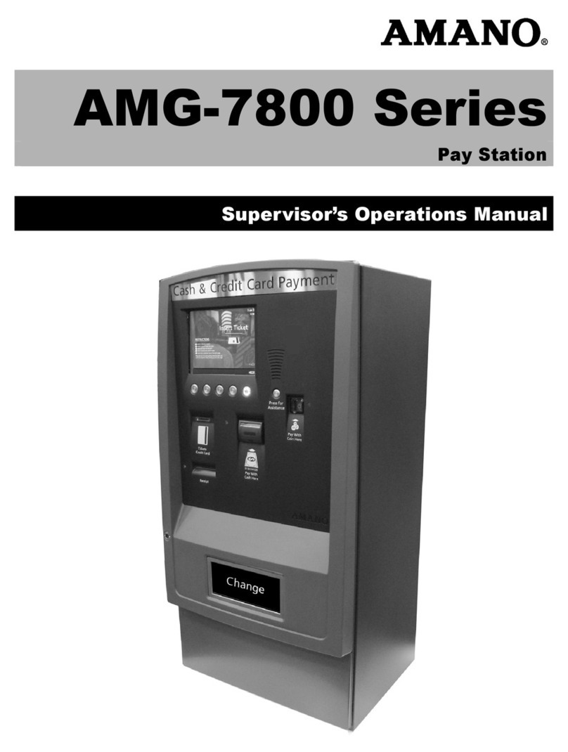
Amano OPU Series User manual

OPUSeries
OPUS-
7000 Series
Pay-in-Lane; Pay on-Foot Station
Installation Manual
OPUS7000_Installation_10032014

© Copyright 2014 Amano McGann, Inc. OPUS7000_Installation_10032014 2
OPUS-7000 Installation Manual
Date:
Tuesday, January 27, 2015
Notice of Rights:
Copyright © 2015 Amano McGann, Inc. All rights reserved. This document contains proprietary information and such
information may not be reproduced whole or in part without written permission from:
Amano McGann, Inc.
2699 Patton Road
Roseville, Minnesota 55113
Notice of Liability:
Amano makes no representations or warranties with respect to the accuracy or completeness of the contents of this work
and specifically disclaim all warranties, including without limitation, warranties of fitness for a particular purpose. Amano
reserves the right to make equipment changes and improvements that may not be reflected in this document. Portions of
this document may have been updated to include the latest hardware or firmware version, if applicable.
We recommend that this document be read in its entirety before any attempt is made to operate the equipment.
Trademark Notice:
Amano is a registered trademark of Amano Inc. All other trademarks are the property of their respective owners.
Contact Information:
Every effort has been made to ensure the accuracy of this document. If you have comments, question, or ideas regarding
this document please send them to Amano via e-mail to:
techwriter@amanomcgann.com
or, via postal mail to:
Amano McGann, Inc.
Technical Writer
2699 Patton Road
Roseville, Minnesota 55113
For more information about Amano’s complete line of products, visit our web site at:
www.amanomcgann.com
Date
Tuesday, January 27, 2015
Product
OPUS-7000
Build/Revision
OPUS-7000
Model
Pay-in-Lane; Pay-on-Foot Station
Document Type
Installation Manual
Version
A2
Company Name - Long
Amano McGann, Inc.
Company Name - Short
Amano McGann
Street
2699 Patton Road
City/State/Postal Code
Roseville, Minnesota 55113
Telephone
(612) 331-2020
Fax
(612) 331-5187
Email
Website
www.amanomcgann.com
Copyright
Copyright © 2014 Amano McGann, Inc. All rights reserved.
File Name
OPUS7000_Installation_10032014

© Copyright 2014 Amano McGann, Inc. OPUS7000_Installation_10032014 3
OPUS-7000 Installation Manual
OPUS-7000 INSTALLATION
MANUAL
OPUS-7000 INSTALLATION MANUAL
Introduction............................................................................................................... 5
File References........................................................................................................ 5
BEFORE YOU BEGIN.................................................................................................... 6
1.1 Receiving............................................................................................................ 6
1.2 Removing Packaging Material............................................................................ 7
1.3 Inspecting the Equipment.................................................................................... 8
1.4 Preparing the Site................................................................................................ 8
1.5 Cut Sheets........................................................................................................... 9
1.6 External Drawing................................................................................................. 12
1.7 Internal Drawing................................................................................................. 13
1.8 Architectural Map................................................................................................ 14
1.9 Wiring Conduit (OPUS-7700).............................................................................. 15
1.10 Mounting Diagram............................................................................................. 16
1.10.1 Mounting Instructions.............................................................................. 16
1.11 Specifications................................................................................................... 17
OPUS-7000 PROCEDURES.......................................................................................... 19
2.1 Opening the Paystation Door.............................................................................. 19
2.2 Powering ON the Paystation.............................................................................. 19
2.3 Entering the Management Menus...................................................................... 19
2.4 Removing and Opening the Bank Note Vault.................................................... 20
2.5 Removing the Bank Note Acceptor.................................................................... 21
2.5.1 Checking Bank Note Acceptor Firmware................................................. 22
2.6 Accessing the Coin Vault................................................................................. 22
2.7 Connecting the Ethernet Cable....................................................................... 23
2.8 Installing the Receipt Paper............................................................................. 24
2.9 Removing the Coin Hoppers............................................................................ 25
2.10 Accessing the Coin Dispenser Door............................................................... 26
2.11 Accessing the Bank Note Recylcer.................................................................. 26
2.11.1 Removing the Bank Note Recycler Cassettes....................................... 26
2.12 Inserting a Receipt Header Logo.................................................................... 27
2.13 Enabling the Lost Ticket Button (Negotiated and Flat Fee)............................. 27
VERSION VERIFICATION............................................................................................. 28
3.0.1 Hardware Checklist.................................................................................. 28
3.0.2 Software Checklist.................................................................................... 28
3.1 Verify Current Firmware Versions...................................................................... 28
3.1.1 Windows CE & SmartCash CLM............................................................... 28
3.2 Device Binaries.................................................................................................. 29
3.3 IO-100................................................................................................................ 30
UPDATING SOFTWARE & FIRMWARE...................................................................... 31
4.1 Updating the Windows CE Image...................................................................... 31
4.2 Updating the SmartCash/CLM Firmware.......................................................... 32
4.3 Updating the IO100.......................................................................................... 33
4.3.1 IO100 Revision r791 and Earlier............................................................ 33
4.3.2 Revision 792 and Above........................................................................ 34
4.4 Updating REPM Firmware................................................................................ 36
4.5 Updating the REPM Imager............................................................................... 37

© Copyright 2014 Amano McGann, Inc. OPUS7000_Installation_10032014 4
OPUS-7000 Installation Manual
4.6 Updating the Device Binaries............................................................................ 39
CONFIGURING THE PAYSTATION............................................................................ 40
5.1 Creating Management Cards.............................................................................. 40
5.2 Configuring Parameters..................................................................................... 41
5.3 Configuring Revenue Management.................................................................... 41
5.4 Initial Fill.............................................................................................................. 42
WIRING DIAGRAMS....................................................................................................... 43
6.1 1700 Gate.......................................................................................................... 43
6.2 1703.................................................................................................................... 44
6.3 AiPhone Intercom............................................................................................... 45
6.4 Wiring Schematics.............................................................................................. 46

© Copyright 2014 Amano McGann, Inc. OPUS7000_Installation_10032014 5
OPUS-7000 Installation Manual
Introduction
The OPUS-7000 Series Central Pay-on-Foot, Pay-in-
Lane Station is designed for flexibility and ease of use
in any facility. The fully functional, touch screen
controlled device is the perfect solution 24/7
unattended operations. The OPUS-7000 Series
Paystation processes encrypted 2D data matrix
barcode tickets from the OPUS-2000 Series Entry
Terminal. Payment options include credit card, bills,
coins, and/or encrypted 2D data matrix barcode bulk
validation tickets. Mobile and barcode validations can
also be processed through the optional FlexScan
QR400® barcode imager.
The OPUS-7000 series models are:
•OPUS-7700: Pay-in-Lane Station
•OPUS-7800: Pay-on-Foot Station
Note: The references in this manual to “Device”, “Paystation”, or
“OPUS-7000” refer to both OPUS-7700 and OPUS-7800 series
models. Any direction that does not apply to both series will be
clarified in the appropriate section.
File References
Any file references made in this manual refers to files available on Amano
McGann University (amu.amanomcgann.com). Please contact

© Copyright 2014 Amano McGann, Inc. OPUS7000_Installation_10032014 6
OPUS-7000 Installation Manual
BEFORE YOU BEGIN
1.1 Receiving
The shipment should be thoroughly inspected as soon as it is received. The
signed bill of lading is acknowledgment by the carrier of receipt in good condition
of shipment covered by your invoice. If any of the goods called for in this bill of
lading are shorted or damaged, DO NOT accept them until the carrier makes a
notation on the freight bill of the shorted or damaged goods.
Notify the carrier at once if any hidden loss or damage is discovered after receipt,
and request the carrier make an inspection. If the carrier will not do so, prepare a
signed statement to the effect that you have notified the carrier on a specific date
and the carrier has failed to comply with the request.
Support your claim with copies of the bill of lading, freight bill, invoice, and
photographs, if available. Amano McGann, Inc. is not responsible for collection of
claims or replacement of lost or damaged goods.

© Copyright 2014 Amano McGann, Inc. OPUS7000_Installation_10032014 7
OPUS-7000 Installation Manual
1.2 Remove Packaging Material
1. Remove the tape from the coin change bin and remove the side door keys.
[Fig. 1.2A] Remove the tape and side door keys from the coin change bin
2. Remove the ticket vault box. The ticket vault box contains the accessory bag.
3. Remove the keys, receipt paper, eye bolts, and function cards from the bag.
4. Remove the zip tie on the receipt printer roller.
5. Remove the warning label and zip tie securing the REPM.
[Fig. 1.2B] Remove the zip tie.
6. Remove the keys from the coin box.

© Copyright 2014 Amano McGann, Inc. OPUS7000_Installation_10032014 8
OPUS-7000 Installation Manual
1.3 Inspecting the Equipment
After the OPUS-7000 Paystation has been received, confirm all parts are
included. The Paystation is shipped mounted on a pallet surrounded by a
wooden frame. A plastic mounting template is included. Any optional accessories
are packaged separately.
Note: Notify Amano McGann if any items are missing. Check the
shipping cartons for damage. If anything is damaged, notify the
transportation company and file a claim. The transportation company
is responsible for the shipment after the device leaves the factory.
The box of accessories contains the following items:
Vault box
(2) Eye Bolts
(10) Function Cards (2 Sets)
Refilling Card
Adjustment Card
Operator Card
Management Card
Subtotal Card
Set of keys for the coin box
(4) ‘66’ keys
(4) ‘68’ keys
Receipt Paper
1.4 Preparing the Site
Prior to the installation of the Paystation, please make initial preparations at the
installation site. The customer is responsible for providing electrical service to the
Paystation. The electrical service must meet national, state, local, and Amano
McGann’s operating specifications. The customer is responsible for making any
changes necessary to supply a constant, noise free power line to the OPUS-
7000.
Note: It is recommended the OPUS-7000 be protected to prevent the
introduction of standing and/or blowing moisture, dust, sand, or other
contaminants into the unit.
The OPUS-7000 meets ADA specifications (Americans with Disabilities Act).
Refer to the Architectural Map section for a typical site configuration.

© Copyright 2014 Amano McGann, Inc. OPUS7000_Installation_10032014 9
OPUS-7000 Installation Manual
1.5 Cut Sheets
cm
[inches]

© Copyright 2014 Amano McGann, Inc. OPUS7000_Installation_10032014 10
OPUS-7000 Installation Manual
cm
[inches]

© Copyright 2014 Amano McGann, Inc. OPUS7000_Installation_10032014 11
OPUS-7000 Installation Manual
cm
[inches]

© Copyright 2014 Amano McGann, Inc. OPUS7000_Installation_10032014 12
OPUS-7000 Installation Manual
1.6 External Drawing

© Copyright 2014 Amano McGann, Inc. OPUS7000_Installation_10032014 13
OPUS-7000 Installation Manual
1.7 Internal Drawing

© Copyright 2014 Amano McGann, Inc. OPUS7000_Installation_10032014 14
OPUS-7000 Installation Manual
1.8 Architectural Map

© Copyright 2014 Amano McGann, Inc. OPUS7000_Installation_10032014 15
OPUS-7000 Installation Manual
1.9 Wiring Conduit (OPUS-7700)

© Copyright 2014 Amano McGann, Inc. OPUS7000_Installation_10032014 16
OPUS-7000 Installation Manual
1.10 Mounting Diagram
1.10.1 Mounting Instructions
1. Open the Paystation door
2. Remove the Paystation mounting base from the Paystation by unbolting the
mounting bolts at the bottom of the device
3. The mounting base will detach from the Paystation.
4. Position the Paystation mounting base on the mounting surface and mark the
location of the four mounting holes.
5. Using the marked locations, drill the four mounting holes and bolt the
mounting base to the mounting surface.
6. Position the Paystation on top of the mounting base and open the Paystation
door.
7. Secure the Paystation to the mounting base using the four mounting bolts.

© Copyright 2014 Amano McGann, Inc. OPUS7000_Installation_10032014 17
OPUS-7000 Installation Manual
1.11 Specifications
Compliance
ROHS Compliant
OPUS-7000 Paystation does not store credit card data
Meets ADA (Americans with Disabilities Act) and ANSI (American National
Standards Institute) requirements
Electrical
Power Source: 120 VAC, 60 Hz
Utilization: 12 amp maximum
Mechanical
Thermal printer; exclusive REPM™ (read, encode, print mechanism)
Time Control
Real-time clock synchronization with host computer
Environment
Temperature: -20°F ~ 120°F (-29°C ~ 49°C)
Humidity: 10% ~ 90% (non-condensing)
Housing
Height: 60.22” (152.9 cm)
Width: 24.53” (62.3 cm)
Depth: 24.72” (62.7 cm)
Weight: 390 lbs. (177 kg)
Construction: Sheet steel housing
Cabinet finish: Textured powder coat finish OPUS (RAL#7022); Custom color
available
Door Finish: Metal door with painted molded plastic overlay
Thermal Ticket Printer
High density 300 DPI (dots per inch) thermal print head
Prints date and time (24-hour format), ticket number, machine number and rate
Stores image for electronic ticket tracking (optional), patent pending
2D barcode imager and scanner processes multiple barcodes
Holds first ticket and allows servicing of second ticket
Marks and voids retracted tickets
Receipt Printer
Thermal Print
Auto retract
FlexScan QR400 Barcode Imager Option
Opening: 5”W x 2.6”H (12.7 cm x6.6 cm)
Barcode Types: 1D (Linear) & 2D (QR)
Ambient Light: Total darkness to 9000 ft. candles (96,900 LUX)
Options
Magstripe and proximity access card models optional
TCP/IP security camera optional
Chip and Pin Optional
Security
Multi-point safety lock system
Intruder alarm
Security locks on money handling compartments

© Copyright 2014 Amano McGann, Inc. OPUS7000_Installation_10032014 18
OPUS-7000 Installation Manual
1.11 Specifications (contd.)
Intercom
Aiphone™ LEF series intercom system standard, additional options available
Standard voice announcement
Safe Box
1000 Note Capacity
+/- Coin Capacity; denomination dependent
Programming
Online via local facility controller
Local via Paystation touch screen display
Voice Unit
Delivers pre-programmed verbal instructions to patrons
Messages are user programmable .wav files
Built in intercom for direct communication
Display
LCD touch screen with backlight
Optional language display text and voice
Bill Handling
Cash Code Bill Note Recycler
Coin Handling
Tube: Cash Code, C2 Spider, 6 Tubes
Hopper: Cash Code, C2 Spider, 2 Hoppers

© Copyright 2014 Amano McGann, Inc. OPUS7000_Installation_10032014 19
OPUS-7000 Installation Manual
OPUS-7000 PROCEDURES
2.1 Opening the Paystation Door
1. Insert two of the main door access keys into the upper and lower locks of the
Paystation.
2. Push the key in and simultaneously turn the key 90 degrees to the left.
3. Unlock the remaining lock.
4. Pull the Paystation door to open.
2.2 Powering ON the Paystation
1. Open the Paystation door.
2. The power button is a red rocker switch located in the lower-right section of
the Paystation. Flip the rocker switch upwards to turn the Paystation ON.
IMPORTANT: Please do not turn the Paystation ON immediately after
the Paystation is turned OFF. It is recommended to wait five seconds
as the sudden power can damage Paystation hardware.
2.3 Entering the Management Menus
To configure the internal settings of the Paystation, the Management Switch
needs to be toggled while the Paystation is in its idle state.
1. Verify the Paystation is ON and Idle.
2. Open the Paystation door.
3. Toggle the Management Switch located in front of the iCore board. The
Paystation displays the First Time Operation menu.
[Fig 2.3A] Management Switch

© Copyright 2014 Amano McGann, Inc. OPUS7000_Installation_10032014 20
OPUS-7000 Installation Manual
2.4 Removing and Opening the Bank Note Vault
The Bank Note Vault needs to be removed from the Paystation when the
vault is to be emptied of its contents. Follow the instructions below to remove
the bank vault from the Paystation and remove the notes from the vault.
1. Unlock and open the Paystation door.
2. Insert the ‘66’ key into the lock located under the note vault.
3. Push the key inwards and turn the key 90 degrees to the right/clockwise until
the key stops.
4. Fold the vault handles back.
5. Push in the blue button on the top-right of the vault drawer (pictured below)
and simultaneously pull the vault out using the vault handles.
[Fig. 2.4A] Press and hold in the blue vault drawer release
button after the vault drawer has been unlocked.
6. Take the vault to the location designated by the facility once the vault has
been removed.
7. Flip the vault over so the “OPEN” switch is on top.
8. Insert the ‘68’ key into the lock, push in the key and simultaneously rotate the
key towards the vault front/vault handle until the key stops.
9. Rotate the OPEN switch in the direction of the arrow/counter-clockwise.
10. Pull off the top of the vault and unload the money.
11. Follow the previous steps in reverse order to close the bank note vault and
re-insert the vault into the Paystation.
Other manuals for OPU Series
1
This manual suits for next models
1
Table of contents
Other Amano Payment Terminal manuals
