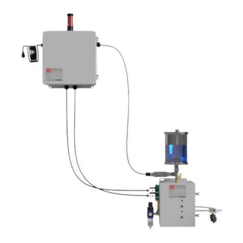
AMCOL 3049B User manual

AMCOL CORPORATION
3049B AUTOMATIC BUTT
DISCARD LUBRICATION SYSTEM
OPERATOR’S MANUAL

3049B AUTOMATIC BUTT DISCARD LUBRICATION SYSTEM OPERATOR’S MANUAL PAGE | 1
File ID: 3049-OM04
Approved for Use
LSB: AA-0025
LSD: 3/10/2022
FDR: PS04
Contents
1. Introduction ......................................................................................................................................2
2. What Do I Have?..............................................................................................................................3
3. Assembly and Installation ...............................................................................................................4
PRIOR TO GETTING STARTED............................................................................................................4
Installation .........................................................................................................................................5
4. Recommended Settings.................................................................................................................8
5. Operation .........................................................................................................................................9
Proper Operation...........................................................................................................................10
6. BL 463 2S EJECTEZE.........................................................................................................................11
PA201 Refractometer ....................................................................................................................11
7. System Troubleshooting ................................................................................................................12
No Liquid .........................................................................................................................................12
Too Much Liquid.............................................................................................................................12
Too Little or Inconsistent Liquid.....................................................................................................12
Fluid Runs on After Spray...............................................................................................................12
8. Maintenance .................................................................................................................................13
Recommended Spares .................................................................................................................13
Preventative and Predictive Maintenance ...............................................................................16
9. Schematics .....................................................................................................................................17
System Schematic .........................................................................................................................17
202 Spray Nozzle ............................................................................................................................18
Reservoir ..........................................................................................................................................19
Valve Package ..............................................................................................................................19
Hose and Manifold ........................................................................................................................20
AMCOL Corporation
21435 Dequindre, Hazel Park, MI 48030
248-414-5700
fax: 248-414-7489
www.amcolcorp.com

3049B AUTOMATIC BUTT DISCARD LUBRICATION SYSTEM OPERATOR’S MANUAL PAGE | 2
1. Introduction
This operator’s manual is designed to walk you through the installation, all the way to
operation and maintenance of your new AMCOL 3049B Spray System. For more information
on the overview of the system and the individual components, please refer to the AMCOL
3049B Technical Description.

3049B AUTOMATIC BUTT DISCARD LUBRICATION SYSTEM OPERATOR’S MANUAL PAGE | 3
2. What Do I Have?
1. 202 Atomizing Spray Nozzles (2 ea.)
a. Spray Tips (90° Conical or Fan)
b. Brass Extensions
c. Multidirectional Mounting Bracket
d. Mounting Magnet
2. Hose
a. 2x 5’ (Reservoir to Valve Package)
b. 2x 15’ (Valve Package to Manifold)
c. 2x 7’ (Manifold to Spray Nozzles)
3. Reservoir
a. 10 Gallon
4. Valve Package
a. 24VDC
b. 110VAC
c. 220VAC
5. Manifold
a. Gauge and quick connect fittings for hoses
4
3
2
1
5

3049B AUTOMATIC BUTT DISCARD LUBRICATION SYSTEM OPERATOR’S MANUAL PAGE | 4
3. Assembly and Installation
PRIOR TO GETTING STARTED
•
PLEASE GO TO https://amcolcorp.com/amcol-model-3049-set-up-video/ AND WATCH THE
SET UP VIDEO.
•
WARNING! DO NOT DISASSEMBLE, REPAIR, OR REPLACE COMPONENTS OR SUBASSEMBLIES OF
THIS SYSTEM WITHOUT FIRST DEENERGIZING THE SYSTEM AIR SOURCE WITH LOCK AND TAG; THIS
CAN BE TESTED BY VISUALLY INSPECTING THE PRIMARY AIR GAUGE (B) ON THE VALVE PACKAGE TO
BE AT 0 PSI AND MANUALLY ATTEMPTING TO ACTUATE EITHER THREE-WAY AIR VALVE ON THE VALVE
PACKAGE.
•
WARNING! BE SURE THAT THE PRESS IS PROPERLY GUARDED IN ORDER TO AVOID INADVERTENT OR
UNINTENDED ACCESS TO THE SPRAY HEAD BY UNTRAINED PERSONNEL. REFERENCE ANSI B11.17 OR
SIMILAR PRESS GUARDING STANDARDS.
•
WARNING! BE SURE TO MOUNT THE RESERVOIR AND VALVE PACKAGE OUTSIDE OF THE GUARDED
AREA, AS THEY WILL HAVE TO BE ACCESSED DURING NORMAL PRESS OPERATION.
•
WARNING! DO NOT ATTEMPT TO ADJUST OR MODIFY NOZZLES, WHICH WILL BE WITHIN THE
GUARDED AREA, WITHOUT DEENERGIZING THE PRESS WITH LOCK AND TAG.
•
WARNING! THE SYSTEM IS NOT DESIGNED OR CAPABLE OF DISPENSING FLAMMABLE OR
COMBUSTIBLE LIQUIDS.
•
WARNING! USE PROPER EYE PROTECTION WITH SIDE SHIELDS WHEN IN THE AREA OF OPERATION.
DURING TESTING AND SUBSEQUENT SYSTEM REPAIR, IT IS STRONGLY RECOMMENDED TO USE FULL-
FACE SHIELD PROTECTION.
•
WARNING! IN ORDDER TO UTILIZE THE MAGNETIC SPRAY ASSEMBLY MOUNTING OPTION, THE
MAGNET MUST BE CONNECTED TO A CLEAN FLAT STEEL SURFACE; IN THE EVEN THAT A FIRM
MAGNETIC MOUNT IS NOT POSSIBLE, ELIMINATE THE MAGNET AND PERMANENTLY MOUNT THE
NOZZLE ASSEMBLY USING THE BRACKET PROVIDED.
•
WARNING! THIS SYSTEM IS OUTFITTED WITH A MAGNETIC SPRAY NOZZLE MOUNTING DESIGN IN
ORDER TO AVOID CATASTROPIC DAMAGE TO THE NOZZLE WHEN IT IS INADVERTNTLY HIT (I.E. FLARE
OUT). BE SURE TO PROPERLY DEENERGIZE THE PRESS WITH LOCK AND TAG IF REPLACING THE
NOZZLES THAT HAVE BEEN INADVERTENTLY MOVED OR REQUIRE INSPECTION/MAINTENANCE. IN
GENERAL, IT IS RECOMMENEDED THAT EVEUNTUALLY, THE MAGNETIC MOUNT BE CONVERTED TO A
PERMANENT THREAD MOUNT AND GUARDED SO AS TO AVOID THIS TYPE OF ACTIVITY ALL
TOGETHER.

3049B AUTOMATIC BUTT DISCARD LUBRICATION SYSTEM OPERATOR’S MANUAL PAGE | 5
Installation
1. Review complete system to ensure that damage has not occurred in shipment.
2. Manually operate the system outside of the press area. This can be completed by
connecting all components as per the schematic provided, connecting plant air to the
valve package, and then pressing the manual actuation buttons located on the side of the
Norgren 3-way valves located on the Valve Package. All components will come in preset
according to the System Settings recommended in this bulletin. During manual operation, it
should be confirmed that these components are set accordingly and the spray volume and
pattern is acceptable. In the event that the settings specific to your operation vary from
those recommended by AMCOL, these should be recorded and controlled for later access
and training.
3. With the press in normal operating conditions and standing outside of the press guarding,
observe potential areas for installation of the nozzles, reservoir, and valve package. The
nozzles will have to fit without being hit by moving components of the press. The valve
package will have to be outside the press guarding and ideally within sight of the operator
and spray nozzles, yet out of general traffic area. The reservoir should also be outside of the
press guarding and close to the valve package
4. Lock and Tag the press. Then place the atomizing nozzle assemblies in the expected
position without the hose attachments in order to properly assess and approve the exact
placement of them. Exit the lock and tag area and reactivate the press with the nozzle in
position in order to determine that the nozzle is in a position so as to avoid damage during
normal press operation. Once the exact location is determined, mark the location or
permanently mount the nozzles accordingly for future reference and placement after
servicing or other movement of the nozzle and spray assembly. Hints for placement:
A. Butt Shear – on the press platen, shear housing, or top of the container (with fan
spray).
B. Log Shear – on the press platen from the exit side of the shear.
5. Permanently mount the liquid air manifold block above the spray nozzles such that it is
located within seven feet (7’) of both atomizers. Also, be sure the manifold block is visible
from outside the lock and tag area in order to allow for system inspection and monitoring
during normal press operation.
6. Mount the Valve Package as previously determined. The Valve Package air and liquid
outlets must be within fifteen feet (15’) of the liquid and air manifold, which has already
been installed on the press.
7. Connect a lightly lubricated ½” air line to the air inlet of valve package. Be sure that this
air source is properly locked and tagged prior to beginning your installation. Do not
energize until all hoses have been properly installed and attached.
3049B AUTOMATIC BUTT DISCARD LUBRICATION SYSTEM OPERATOR’S MANUAL PAGE | 6
8. Connect hoses as supplied with the system. Any hose that is longer than required to make
a proper connection should be shortened where possible.

3049B AUTOMATIC BUTT DISCARD LUBRICATION SYSTEM OPERATOR’S MANUAL PAGE | 7
9. Energize the air source and manually operate the Valve Package (as per directions in
step 1).
10. Assuming the system is now operational, and the system settings are acceptable, de-
energize the air to the Valve Package and finalize the PLC connection of the Norgren 3-
way valves located on the Valve Package to the press PLC with the sequencing and timing.
Be sure to spray the Butt Shear while the container is closed and the Log Shear while empty
and in the Open Position. It is generally recommended that a manual actuation option is
available from the press operator control station.
11. Reenergize the air source to the valve package, and the spray system should be
operational in automatic mode.

3049B AUTOMATIC BUTT DISCARD LUBRICATION SYSTEM OPERATOR’S MANUAL PAGE | 8
4. Recommended Settings
Item ID
Description
Recommended Setting (and Explanation)
A
System
Shutoff
Open during normal operation – Close to perform
repairs. Has lock and tag eyelet.
B
Spray
Pressure
Regulator
40 PSI. This is the valve package inlet pressure. It
can be set with no valves energized. This air
pressure determines spray pressure when the liquid
and air are both energized.
C
Spray Valve
(back valve)
Energize for the first 0.5 seconds and then
deenergize. Actuating this valve opens liquid at the
valve package (liquid safety switch) and air and
liquid at the atomizing nozzle.
D
Blow Out
Valve (front
valve)
0.5 seconds after deenergizing the spray valve,
energize the blow out valve for 2.5 seconds or
more. This valve is used to clear the liquid from the
spray tubes and will only supply air to the nozzle.
E
Blow Out
Pressure
Regulator
20 PSI. This is the air pressure when the blow out
valve is energized. It can be set by manually
actuating the valve and subsequently adjusting
the regulator. If this pressure is set too high (above
30 PSI), the 202 nozzles will be opened and the
spray cycle will continue.
F
Pump Inlet
Pressure
50 PSI Minimum. Increase pressure to increase
liquid volume. This will increase pump flow and
outlet pressure. Liquid pressure at the 202 atomizers
must be above the Spray Pressure (A) in order to
avoid backpressure inconsistencies.
G
Pump Shutoff
Open during normal operation. Allows for quick
shut off of reservoir pump in the event of an
emergency involving a leaking valve, hose, or
strainer.
H
Fluid
Recirculation
Ball Valve
<10% Open (for 30 cycles per minute). This valve
adjusts the recirculation flow back to the reservoir
and pressure to the nozzle. As this valve is opened,
the flow rate to the reservoir increases, while the
liquid pressure to the nozzle is reduced.
I
202 Dial
Setting
4 CCW Turns from Off. As used in this equipment,
this is merely a macro adjustment. Liquid is shut off
when the knob is adjusted tight in the clockwise
direction; flow is increased by then rotating in a
counterclockwise direction.
J
Needle
Valve Setting
3 CCW Turns from Off. This adjustment is used to set
an exacting liquid flow. Liquid is shut off when the
knob is adjusted tight in the clockwise direction;
flow is increased by then rotating in a
counterclockwise direction. This adjustment is truly
the liquid volume adjustment. Once set, use pump
pressure or spray time to adjust liquid flow volume
per spray cycle.
A
C
D
E
G
H
I
J
F
B

3049B AUTOMATIC BUTT DISCARD LUBRICATION SYSTEM OPERATOR’S MANUAL PAGE | 9
5. Operation
Prior to Getting Started
•Be sure that all hoses are connected to the appropriate fittings and tightly secured.
•Put enough fluid in the reservoir to allow the system to operate.
•Securely connect an air source to the main air inlet and energize the air line
connected to the system.
Operating the System Shutoff Valve
•Observe Spray Pressure [B] is 0 psi when the System Shutoff valve [A] is closed.
•Open System Shutoff valve[A] and set the Spray Pressure Regulator [B] to 40 psi.
Setting & Operating the Reservoir Pump
•Open the Pump Shutoff valve [G] and set Pump Inlet Pressure [F] to at least 50 psi.
•Open the Fluid Recirculation Valve [H] so that the pump cycles approximately once
every two seconds.
Setting the 202 Nozzle
•Confirm that the 202 Dial [I] is set to four rotations from fully closed.
•Confirm that the Needle Valve [J] on the 202 nozzle is set to 3 rotations from fully
closed and then tighten the set screw.
Setting Nozzle Blow Out Pressure
•Manually actuate the air Blow Out Valve (front valve) [D] and set the Blow Out
Pressure Regulator [E] to 20 psi.
F
D
B
G
H
I
J
E
C
A

3049B AUTOMATIC BUTT DISCARD LUBRICATION SYSTEM OPERATOR’S MANUAL PAGE | 10
Proper Operation
Cycle Timing (Manual)
•The figure below demonstrates the timing sequence used for the manual and
automatic system cycling.
•Be sure to include at least 0.5 second delay between the liquid and blowout cycle
to ensure that the 202 nozzle properly closes and liquid does not continue to be
output during the blow out cycle. Additionally, if the delay is longer than 1 second,
dripping will occur before the blow out cycle is initiated.
Manual Actuation
•Observe pressure changes and the 202 piston [I] open with Spray Valve (back valve)
[C] actuation.
•Observe Blow Out Pressure [E] changes with actuation of the Blow Out Valve (front
valve) [D].
•Due to the length timing gap between liquid and air actuation, expect some
dripping to occur at the tips during manual operation.
Cycle Timing (Automatic)
•There is no dripping during automatic cycling.
•To operate the system automatically, desired settings should be programmed into
the machine PLC. Start by operating the system with the timing sequence shown
below. Spray and blow out timing can be adjusted to optimize the system for the
system for your operation.
0.5 seconds 0.5 seconds 2.5 seconds

3049B AUTOMATIC BUTT DISCARD LUBRICATION SYSTEM OPERATOR’S MANUAL PAGE | 11
6. BL 463 2S EJECTEZE
BL 4632 2S EJECTEZE is a water-
dilutable lubricating fluid. It is
designed to cool as the water
evaporates, then travels by capillary
action to completely coat the tool
steel with a liquid lubricant, leaving
only a light oily residue. There is no
smoke or flame and no known effects
on the extrudate. BL 463 2S EJECTEZE
in combination with the AMCOL 3049B
Spray System will reduce aluminum
build-up and sticking as well as
maximize shear life and cut quality. BL
463 2S EJECTEZE is available for
purchase in 5 gallon pails or 55 gallon
drums.
PA201 Refractometer
The PA201 Refractometer, manufactured by
Misco, is a handheld testing instrument used to
check and monitor dilution ratios of liquid
concentrates that are mixed with water. It is
operated by placing a drop or two of fluid in the
titanium bowl, then pressing the activation button.
A microprocessor will then deliver a nearly
instantaneous digital readout on an LCD display.
This numerical reading can be correlated to a
specific dilution for a given product using a cross reference chart or logarithmic formula.
Calibration is automatic and does not require the use of special calibration solutions or
tools. See the Misco PA201 Refractometer reference manual for additional information.
The Misco PA201 Refractometer is based on the Brix scale reading system. There are many
different types and makes of Refractometers that can be used as a substitute. Be sure that
whatever system is used is reliable and easy to operate.

3049B AUTOMATIC BUTT DISCARD LUBRICATION SYSTEM OPERATOR’S MANUAL PAGE | 12
7. System Troubleshooting
Check in order as listed
No Liquid
•Reservoir is empty or low. Double diaphragm pump will be cycling at a very high rate.
Fill.
•Air pump malfunctioning. Repair or replace.
•Air pressure to nozzle exceeds liquid pressure. Refer to recommended settings.
•Air pressure too low and cannot actuate safety switch (40 psi min.). Refer to
recommended settings.
•Atomizer or safety switch stuck closed. Repair or replace.
•Fluid return ball valve on reservoir not restricted. Refer to recommended settings.
•Air pockets in liquid hose. Manually actuate until volume is consistent.
Too Much Liquid
•Liquid flow misadjusted (see System Settings).
•Spray valve open too long.
•Pump pressure on reservoir too high.
Too Little or Inconsistent Liquid
•Spray extension is clogged or kinked.
•Opposite of Too Much Liquid, as referenced above.
•Nozzle or liquid strainer clogged. Clean.
•Air pockets in liquid hose. Manually actuate until volume is consistent.
Fluid Runs on After Spray
•Spray Valve (back valve) [C] has not been properly deenergized prior to blow out.
•Spray cycle too long. Refer to recommended settings.
•202 Nozzle is malfunctioning. Repair or replace.
•Safety switch malfunctioning. Repair or replace
•Spray Valve (back valve) [C] is not closing properly. Clean, grease, and reassemble.

3049B AUTOMATIC BUTT DISCARD LUBRICATION SYSTEM OPERATOR’S MANUAL PAGE | 13
8. Maintenance
Recommended Spares
Description
Part Number
Quantity
202 Spray Nozzle *
202-018-AC
2 ea.
Repair Kit for 202
04290
2 ea.
P/H Fire Res. Hose (1/4")**
821FR-4-BLK
30 ft.
P/H Fire Res. Hose (3/8")**
821FR-6-BLK
30 ft.
P/H Fire Res. Hose (1/2")**
821FR-8-BLK
15 ft.

3049B AUTOMATIC BUTT DISCARD LUBRICATION SYSTEM OPERATOR’S MANUAL PAGE | 14
1/2" Polypropylene Pump
with PTFE Check Balls (1)
66605J-34B-AC
1 each
Rebuild Kit for 66605J-34B
Diaphragm Pump (1)
637140-4B
1 ea.
Check Balls, ¾” PTFE, for
66605J-34B DP * (1)
93100-4
4 ea.
140 psi Pressure Gauge
(for manifold)
18-013-212
1 ea.
160 psi Pressure Gauge
(for regulators)
18-013-209
1 ea.
Liquid Safety Switch, Pilot
Air Control, 2-Way Valve
01285-PRKR
1 ea.

3049B AUTOMATIC BUTT DISCARD LUBRICATION SYSTEM OPERATOR’S MANUAL PAGE | 15
90 Degree Spray Nozzle
with 6" Pipe ***
13-90DSN-6
2 ea.
Clear Bowl for 1/2 in-line
strainer with Gasket *
9875K11-AC
2 ea.
80 Mesh Replacement
Screen for T-Strainer (SS) *
9875K82
1 ea.
* Strongly recommended
** May be purchased locally
*** Standard option part number
(1) Note: PTFE replaces Santoprene™

3049B AUTOMATIC BUTT DISCARD LUBRICATION SYSTEM OPERATOR’S MANUAL PAGE | 16
Preventative and Predictive Maintenance
Daily
•Observe fluid level and fill as necessary.
•Observe system settings for Reservoir and Valve Package and adjust as necessary.
•Observe spray quality and quantity and adjust as necessary.
•Check fluid dilution using Misco PA201 Digital Refractometer (information regarding the
Misco PA201 can be found below). Correct dilution as necessary. A dilution chart can be
found In the Technical Bulletin for BL 463 2S EJECTEZE.
Quarterly
•Replace 80 Mesh Screen, Clear Bowl, and Gasket.
•Replace Check Balls for Aro Diaphragm Pump (4 ea.).
Biannually
•Completely empty reservoir. Wash with water. Refill.
•Disassemble and rebuild 202 nozzles or completely replace.
Yearly
•All biannual maintenance.
•Replace all liquid and air hoses.
•Disassemble and inspect/repair or replace 3-way air operated solenoid valves on Valve
Package.
•Rebuild or replace Rebuild Kit for 66605J-34B Diaphragm Pump (use PTFE Balls and
Santoprene Diaphragms).

3049B AUTOMATIC BUTT DISCARD LUBRICATION SYSTEM OPERATOR’S MANUAL PAGE | 17
9. Schematics
System Schematic

3049B AUTOMATIC BUTT DISCARD LUBRICATION SYSTEM OPERATOR’S MANUAL PAGE | 18
202 Spray Nozzle
202-MMB-M
202 Internal View

3049B AUTOMATIC BUTT DISCARD LUBRICATION SYSTEM OPERATOR’S MANUAL PAGE | 19
Reservoir
BL-202-10NP
Valve Package
MVO-101BR
Table of contents
Other AMCOL Lubrication System manuals