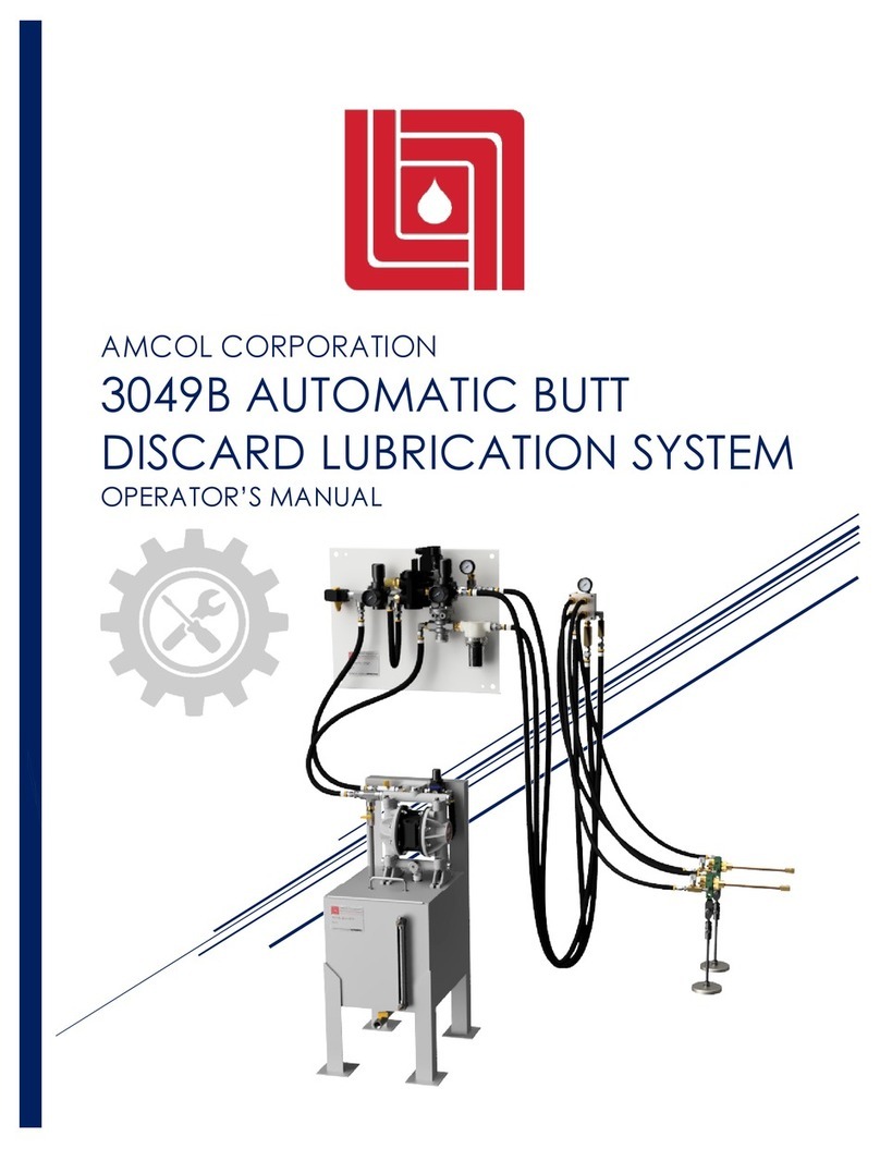
AMCOL 6000E User manual

AMCOL CORPORATION
6000E ELECTRONICALLY
CONTROLLED PRECISION
LUBRICATION SYSTEM
Operator’s Manual

6000E ELECTRONICALLY CONTROLLED PRECISION LUBRICATION SYSTEM
Operator’s Manual
P A G E | 1
File ID: 6000E-OM03
Approved for Use
LSB: AA-0025
LSD: 7/2/2021
FDR: PS04
Contents
1 Introduction ......................................................................................................................................2
2 Included Components....................................................................................................................3
3 Assembly and Installation ...............................................................................................................4
PRIOR TO GETTING STARTED............................................................................................................4
Installation .........................................................................................................................................4
4 Recommended Settings.................................................................................................................5
Settings with SMART Metering.........................................................................................................5
5 Operation .........................................................................................................................................6
6 Priming/Re-priming the System ......................................................................................................8
7 System Troubleshooting ..................................................................................................................8
8 T60A Posi-pump Troubleshooting...................................................................................................9
9 Maintenance .................................................................................................................................11
Recommended Spares.................................................................................................................11
Recommended Tools ....................................................................................................................11
Repair of the T60A Posi-Pump ......................................................................................................12
T60A Posi-pump Bill of Materials ...................................................................................................13
Preventative and Predictive Maintenance ...............................................................................13
Daily .............................................................................................................................................13
Quarterly......................................................................................................................................13
Yearly ...........................................................................................................................................13
10 Recommended Fluids .................................................................................................................14
11 Schematics and Drawings..........................................................................................................15
AMCOL Corporation
21435 Dequindre, Hazel Park, MI 48030
248-414-5700
fax: 248-414-7489
www.amcolcorp.com

6000E ELECTRONICALLY CONTROLLED PRECISION LUBRICATION SYSTEM
Operator’s Manual
P A G E | 2
1 Introduction
The AMCOL 6000E Electronically Controlled Precision Lubrication Applicator is an air
operated spray system used to accurately dispense minute quantities of liquid lubricants
and coatings used in the production and fabrication of metal. With this system, fluids are
injection metered from a gravity reservoir using patented positive displacement piston
pumps and then mixed with air at the spray point. Multi-point lubrication is accomplished
with multiple injectors or by splitting outputs at the spray point.
This operator’s manual describes the installation, operation, and maintenance of
your new AMCOL 6000E Precision Applicator. For more information on the system and the
individual components, please refer to the preceding document: “AMCOL 6000E
ELECTRONICALLY CONTROLLED PRECISION LUBRICATION SYSTEM - Technical Description.”

6000E ELECTRONICALLY CONTROLLED PRECISION LUBRICATION SYSTEM
Operator’s Manual
P A G E | 3
2 Included Components
1. System Controls
2. Gravity Feed Reservoir
3. Air/Liquid Hose to Spray Point
4. Air/Liquid Spray Assembly
Shown is a 6000E Precision Applicator System with a two injector T60A Posi-pump, ½ Gallon
Reservoir with Low Level Indicator, urethane bonded biaxial hose, and B2 Manifold with Air
Propelled Wet Tips on a Compact Multifunctional Mounting Bracket.
For additional information about spray manifolds, nozzle extensions, spray tips, and
mounting brackets, please see the AMCOL 6000 Series Spray Assemblies- Technical
Description and Operator’s Manual.
For additional information about simple electronic control for 6000E Series Applicators, see
the AMCOL 6000-ETC Technical Description and Operator’s Manual.
2
4
3
1
1

6000E ELECTRONICALLY CONTROLLED PRECISION LUBRICATION SYSTEM
Operator’s Manual
P A G E | 4
3 Assembly and Installation
PRIOR TO GETTING STARTED
•WARNING! The AMCOL 6000E series applicator is serviced by a high-pressure air source.
Pressurized air is inherently dangerous and only qualified individuals should be allowed to
work on these systems.
•WARNING! Wear safety glasses at all times.
•WARNING! Lock out service air during assembly, disassembly, and related repairs.
•WARNING! Tighten all hose and fittings prior to operation.
•WARNING! Only use fluids that are compatible with aluminum, brass, steel, urethane,
nylon, and acrylic.
Installation
1. Review your applicator to see that no damage has occurred in shipment.
2. See that all your components and the related mounting is appropriate for your piece
of equipment.
3. Ensure that your plant air source has the required capacity and is available, clean,
and dry.
4. Mount the system controls in a protected area, which can be easily accessed by
operations and maintenance personnel. Some components may require minor
assembly as they have been shipped independently to avoid damage in transit.
5. Attach liquid reservoir to the system controls.
6. Mount transition blocks/manifold to the machine, while carefully observing that
these items will not interfere with the activities associated with the use, maintenance
and adjustment or your machine.
7. Spray tips should be mounted at the maximum distance from and directly at the
spray target. This may require additional adjustments once the system is fully
operational.
8. Connect system actuation to your machine controls; air pulse injection rate may also
require an additional actuation source.
9. Connect plant air source and set the filter-regulator to 60 psi.
10. Fill the liquid reservoir and then open the shut-off valve on the bottom of the
reservoir.
11. Manually actuate system, observing that system is leak free and all adjustments are
operational. (The manual actuator is a push button over-ride recessed on top of the
solenoid)
12. Under careful observation, operate system in production environment.
6000E ELECTRONICALLY CONTROLLED PRECISION LUBRICATION SYSTEM
Operator’s Manual
P A G E | 5
4 Recommended Settings
Item ID
Description
Recommended Setting
A
System Air Pressure
60 PSI
B
Injection Pulse Rate Solenoid
According to machine cycle rate and volume
C
Dispersing Air Solenoid
According to machine cycle rate
D
Dispersing Air Pressure
20 PSI as a starting point. Adjustment of the flow
control at the transition block is highly
dependent on spray tip. Adjust as needed, DO
NOT mist or fog!
E
Injection Volume
Start at 1.5 turns open from off (fixed injection
volume is also available)
Settings with SMART Metering
All 6000E systems include a dual solenoid control package that eliminates the
variability of traditional pneumatic controls. Fixed position hex caps and non-
adjustable regulators remove variability associated with spray volume and pattern.
•Fixed hex caps use set screws and epoxy to lock the distance of the
adjustment screw inside the hex cap. This allows for a consistent, minimal fluid
output to remove variability in spray volume.
•Nonadjustable regulators remove the variability in adjustable regulators,
allowing for a consistent spray pattern at the spray point.
Using a combination of SMART Metering components, all variability of a 6000E
system can be remove, allowing the spray volume to be solely based on injection
rate of the T60A pump.
B
D
E
C
System
Air In
Air Liquid
Liquid Out
To Spray Point
Air Out
To Spray Point
A

6000E ELECTRONICALLY CONTROLLED PRECISION LUBRICATION SYSTEM
Operator’s Manual
P A G E | 6
5 Operation
Before Getting Started
•Ensure all hoses are connected to the appropriate fittings and are tightly secured.
•Ensure all wiring connections to the solenoids are secure.
•Refill reservoir if low or empty.
•Securely connect an air source to the system air regulator. Check system pressure
(60 psi recommended).
•Re-prime the system if liquid is not at the spray point.
Operating the Dispersing Air Solenoid
•Observe 0 psi on the Dispersing Air Regulator when closed.
•Manually open the solenoid and set the Dispersing Air Pressure.
Operating the Injection Pulse Rate Solenoid
•Observe no fluid output when the Pulse Rate Solenoid is closed.
•Manually actuate the solenoid and observe the fluid output. Modify injection volume
settings accordingly (clockwise to decrease, counterclockwise to increase).
Setting Injection Pulse Rate
•The Injection Pulse Rate Solenoid is programmed and controlled with your PLC.
•T60A Posi-pumps can be cycled up to 10 times per second using the following timing:
oInjection Pulse Rate Solenoid open for 20ms
oInjection Pulse Rate Solenoid closed for 80ms
•If using a 6000-ETC, simply press the up or down buttons on the PLC to modify
Injection Rate without any changes to programming. See the AMCOL 6000 ETC
Technical Description and Operator’s Manual for more information.
Proper Operation
System Timing
Correct system timing can be seen to the left. SV1 is the
Dispersing Air Solenoid and should be kept on during for the
full duration of the spray cycle (T1). SV2 is the Injection Pulse
Rate Solenoid, which should be actuated according to the
desired cycle rate (T2), up to 10 times per second.

6000E ELECTRONICALLY CONTROLLED PRECISION LUBRICATION SYSTEM
Operator’s Manual
P A G E | 7
Manual Actuation
To manually test the system to observe spray output, perform the
following:
•Activate the Dispersing Air Solenoid. This solenoid should
remain open while testing spray volume and pattern. If this
solenoid is not activated, liquid will only drip out of the spray
tips instead of being forced out with air.
•Pulse the Injection Pulse Rate Solenoid at a regular rate.
Each actuation corresponds to 1 injection cycle.
Manual operation should be used to verify current settings, test
spray coating, and troubleshoot.
Automatic Actuation
To automatically use the 6000E system, it
should be interfaced with the control PLC,
which should contain the following sequence:
•Activate the Dispersing Air Solenoid
whenever the 6000E is operating.
•Pulse the Injection Pulse Rate Solenoid at
the desired rate.
•Ensure the settings do not exceed the
minimum 20ms “on” or 80ms “off” times, or the
T60A pump will not operate.
While running automatically, the spray
volume and pattern should be consistent. No
misting or fogging should be present. See
Section 7 for troubleshooting.
To manually activate the solenoid, press the manual
override button here:

6000E ELECTRONICALLY CONTROLLED PRECISION LUBRICATION SYSTEM
Operator’s Manual
P A G E | 8
6Priming/Re-priming the System
1. Fill the reservoir.
2. Open the ball valve on the bottom of the reservoir.
3. Open pumps by turning the T60A liquid adjustment screw counterclockwise.
4. Repeatedly cycle the injectors.
5. Once liquid reaches the spray point, readjust the T60A Posi-pump to
the desired setting.
6. Adjust spray air pressure if necessary.
7 System Troubleshooting
Check in order as listed
Fluid Volume Inappropriate
•Injectors misadjusted: adjust individual injectors.
•Incorrect cycle timing: readjust Injection Pulse Rate Solenoid.
Inconsistent Spray Volume to One Spray Point
•Spray tip is clogged: simply remove, clean, and replace spray tip.
•Spray tip is not properly attached: be sure spray tip is tightly threaded and secured,
and that the 1/8” liquid line is properly installed onto barbed connectors.
•Spray tip is damaged: remove and replace.
•Liquid or air hose is severed or incorrectly attached: reconnect or replace.
•T60A Posi-pump needs to be rebuilt: see instructions on page 12.
Inconsistent Spray Volume to All Spray Points
•Be sure the fluid reservoir ball valve is open.
•Fluid level is low: refill reservoir.
•Strainer on reservoir is clogged: clean or replace.
Mist or Fog
•Manifolded dispensing air pressure set too high: adjust.
•Individual spray point flow set too high: adjust.
Liquid from Back of Injector
•Injector contact seals leaking: clean injector and replace O-ring.

6000E ELECTRONICALLY CONTROLLED PRECISION LUBRICATION SYSTEM
Operator’s Manual
P A G E | 9
No or Low Dispersing Air
•Manifolded dispersing air pressure set too low: adjust.
•Air hose is kinked or cut: repair or replace.
•Spray tip is clogged: clean or replace.
•Spray tip is damaged: replace.
Air in Liquid Line
•Fluid line is not properly attached to pump: replace hose or fitting.
•Injector seal is failing: rebuild or replace.
Liquid Drains from Spray Tip
•Injector check valve is failing: rebuild or replace.
•Liquid line in single point nozzle assembly is damaged or disconnected: replace
8 T60A Posi-pump Troubleshooting
No Liquid
•Pump is turned off: turn liquid adjustment screw counterclockwise.
•Pump is seized: remove, clean, and rebuild.
•Reservoir is empty: fill.
•Air pressure is too low: adjust to over 60 PSI.
Bubbles from Injectors
•Air seals are leaking: replace.
•Exit fitting is leaking: replace.
Liquid Drains from Injector Outlet
•Exit fitting is leaking: replace.
•Evacuation valve is ineffective: clean or replace.
•Biaxial hose is trimmed incorrectly: be sure hose is cut straight with no burrs or
deformities.

6000E ELECTRONICALLY CONTROLLED PRECISION LUBRICATION SYSTEM
Operator’s Manual
P A G E | 10
Too Much Liquid
•T60A adjustment screw is too far open: adjust clockwise.
Not Enough Liquid
•Too far closed: adjust counterclockwise
•Liquid outlet (or hose) is kinked: replace.
Liquid Volume is Inconsistent
•Injector is contaminated: clean.
•O-ring seal is faulty: replace or rebuild.
Liquid Volume is Increasing with Time
•O-ring on adjustment stem is deteriorated: replace.
Liquid Leaking from Pump Body
•O-ring seals are worn: replace.
•Piston sleeve is not tight: tighten.
•Piston sleeve is worn: rebuild complete injector

6000E ELECTRONICALLY CONTROLLED PRECISION LUBRICATION SYSTEM
Operator’s Manual
P A G E | 11
9 Maintenance
Recommended Spares
Description
Part Number
Quantity
Biaxial hose
6000-B-BH1
10’ per injector
Repair Kit for T60A
T60A-RK
1 per injector
T60A Assembly with Fittings for
6000E
T60A-#-E *
1
Spray assemblies are unique to each 6000 and should be replaced accordingly when
damaged. See the 6000 Series Spray Assemblies Technical Description for information
about the various parts and options.
* Number of injectors on replacement pump must match current system
Recommended Tools
Description
Part Number
Quantity
O-ring repair tool
ORT-T60
1
T-60A repair tool
RT-T60
1

6000E ELECTRONICALLY CONTROLLED PRECISION LUBRICATION SYSTEM
Operator’s Manual
P A G E | 12
Repair of the T60A Posi-Pump
1. Remove brass hex cap from the body using a 7/8” wrench.
2. Unscrew adjustment stem from brass hex cap using standard screwdriver.
3. Thread RT-T60A Repair Tool into threaded hole on top of piston subassembly. Slowly
pull piston assemble straight out of piston sleeve.
4. Remove Helical Spring from Piston Sleeve.
5. Unscrew Piston Sleeve from pump body using the ears on the RT-T60A Repair Tool
and remove.
6. Clean and observe all components, both internally and externally.
7. Using the liquid to be pumped as a lubricant, replace and install all associated
components in reverse order.

6000E ELECTRONICALLY CONTROLLED PRECISION LUBRICATION SYSTEM
Operator’s Manual
P A G E | 13
T60A Posi-pump Bill of Materials
Preventative and Predictive Maintenance
Daily
•Observe fluid level and fill as necessary
•Observe system settings
•Observe system for damage
Quarterly
•Empty, clean, and refill reservoir
•Replace liquid and air hose
Yearly
•Rebuild or replace T60A Posi-pumps

6000E ELECTRONICALLY CONTROLLED PRECISION LUBRICATION SYSTEM
Operator’s Manual
P A G E | 14
10 Recommended Fluids
AMCOL offers a variety of CANMIST High Performance Lubricants to meet your specific
needs. With your new 6000E Electronically Controlled Precision Lubrication System, the
properly matched fluid is of critical importance. Only CANMIST fluids are recommended
and fully compatible with 6000 Spray Systems. Contact an AMCOL representative to select
the right CANMIST fluid for your operation.

6000E ELECTRONICALLY CONTROLLED PRECISION LUBRICATION SYSTEM
Operator’s Manual
P A G E | 15
11 Schematics and Drawings
General schematic for dual air source
Sample System with Components (6000E-24-3-D-D-3-B-A)

6000E ELECTRONICALLY CONTROLLED PRECISION LUBRICATION SYSTEM
Operator’s Manual
P A G E | 16
T60A-2B-1AX-NAR15 Complete Assembly
System Actuation Assembly

6000E ELECTRONICALLY CONTROLLED PRECISION LUBRICATION SYSTEM
Operator’s Manual
P A G E | 17
Top Mounted Reservoir Assemblies
Wall Mounted Reservoir Assemblies

6000E ELECTRONICALLY CONTROLLED PRECISION LUBRICATION SYSTEM
Operator’s Manual
P A G E | 18
6000E Enclosure Assembly (2 Injector Shown)
AMCOL Corporation
21435 Dequindre, Hazel Park, MI 48030
248-414-5700
fax: 248-414-7489
www.amcolcorp.com
Other manuals for 6000E
1
Table of contents
Other AMCOL Lubrication System manuals
Popular Lubrication System manuals by other brands

Pulsarlube
Pulsarlube V series user manual

Pulsarlube
Pulsarlube OL500 user manual

Bijur Delimon
Bijur Delimon V5B quick start guide

Trailer Buddy
Trailer Buddy VAULT owner's manual

Kluber Lubrication
Kluber Lubrication Klubermatic PRO operating instructions

SKF
SKF LINCOLN ATEX PSG1 Series operating instructions