american flame AFVK-SP User manual

American Flame AFVK-SP Valve Kits REV. 10-8-19 Page 1
Warning: Improper installation, adjustment,
alteration, service or maintenance can cause
injury or property damage. Refer to this manual for
assistance or for additional information consult a
qualied installer, service agency or gas supplier.
FOR YOUR SAFETY
WHAT TO DO IF YOU SMELL GAS
- Do not try to light the appliance.
- Do not touch any electrical switch.
- Do not use any phone in your building.
- Immediately call your gas supplier from a
neighbor’s phone. Follow the gas suppliers
instructions.
- If you cannot reach your gas supplier call the re
department.
Important: Read these instructions carefully
before starting installation of your log set.
FOR YOUR SAFETY
Do not store or use gasoline or other ammable
vapors and liquids in the vicinity of this or any other
appliance.
Be sure Flue Damper and Glass Doors are fully
open when operating any vented gas log set.
Young children should be carefully supervised
when they are in same room as the appliance.
Notice: Please leave these instructions for the consumer. Retain for future reference
Models:
AFVK-SP
AFVK-SP-HL
AFVK-SP-MHL
Electronic Safety Pilot System for Vented Gas Logs
IF YOU CANNOT READ OR UNDERSTAND THESE INSTALLATION INSTRUCTIONS DO NOT
ATTEMPT TO INSTALL OR OPERATE
INSTALLATION AND OPERATING INSTRUCTION
This intermittent pilot ignition (IPI) gas valve (Safety Pilot) kit is set up for Natural gas only and designed to be used with
18 to 30-inch gas log sets (up to 120,000 Btu’s). Optional LP conversions kits LPK-18 or LPK-24 are available.
DUE TO HIGH TEMPERATURES THESE MODELS ARE NOT RECOMMENDED FOR
INSTALLATION IN SEE THROUGH FIREPLACES
AF
A M E R I C A N F L A M E
CALIFORNIA PROPOSITION 65
WARNING
This product is designed to operate with one of the
following fuel sources: Liquid Propane or Natural Gas.
The fuel used to operate this product, and the products
of combustion of such fuel, can expose you to chemicals
including Benzene which is known to the State of
California to cause cancer, birth defects and other
reproductive harm and Carbon Monoxide which is known
to the State of California to cause birth defects or other
reproductive harm.
(For more information go to: www.p65Warnings.ca.gov.)

American Flame AFVK-SP Valve Kits REV. 10-8-19 Page 2
DESCRIPTION: This installation manual covers three valve kits; AFVK-SP, AFVK-SP-HL and AFVK-SP-MHL.
Installation is the same for all of the kits however the operation is slightly different. All valve kits are re tested at the
factory to ensure proper operation. Each kit is supplied with a individual rocker switch to enable ON/OFF operation
without the transmitter (if needed) and the ability to have continuous pilot or intermittent pilot ignition (IPI), which only
operates the pilot when the log set is turned ON. See each kit below and their contents.
Table of Contents
Description & Contents Page 2
Valve Kit Models Page 3
Installing into a Pre-Existing Log Set Page 4
Installing with a New Log Set Page 5
Reference Section & Wiring Diagram Page 6
Battery Pack Preparation Page 7
Gas Conversion Page 8
Operation of System Page 9-10
Troubleshooting Page11
Replacement Parts Page 12
Warranty Page12
INSTALLER: Each valve kit is supplied with a (UR3-68) adapter that provides an option
to convert the inlet or outlet gas connection from 3/8" are tting to a 1/2" ared tting.
Simply thread the UR3-68 on to the inlet/outlet gas ared tting as shown in Fig. 1.
Note: No pipe joint compound or thread tape is necessary. Ensure ttings are tight and
test for gas leaks.
Top View
(Back of Valve)
I
n
l
e
t
UR3-68
Fig. 1 Installing UR3-68 to the
inlet or outlet side of gas valve
ON
OFF
HI
LO
PILOT
Continuous
Latching Solenoid DC Motor Drive
ON
ON/OFF
Continuous Pilot
OFF
1
2
3
4
56
7
89
Fig. 2 Carton contents: 1- Valve Kit 2- Pilot Assembly 3- Battery Pack Heat Shield 4- Battery Pack
5- Flex Connector 6- Damper Clamp 7- Adapter Fitting 8- SP1001HL 9- SP1001

American Flame AFVK-SP Valve Kits REV. 10-8-19 Page 3
ON
ON/OFF
Continuous Pilot
OFF
Control Module
Battery Pack
Manual Hi/Lo
Control Knob
ON/Remote
Switch
Continious Pilot
On/O Switch
Gas Valve
AFVK-SP SIDE VIEW
Fig. 3 AFVK-SP: Manual Hi/Lo knob, SP1001
transmitter, damper clamp, ex line, adapter tting
(includes battery pack heat shield & batteries not shown).
Fig. 6 Shows side view of component parts inside the
AFVK-SP valve kit.
ON
OFF
HI
LO
PILOT
Continuous
Control Module
Battery Pack
Gas Valve
Solenoid
ON/Remote
Switch
Continious Pilot
On/O Switch
AFVK-SP-HL Side View
(inside box)
Fig. 4 AFVK-SP-HL: Hi/Lo Solenoid, SP1001HL trans-
mitter, damper clamp, ex line, adapter tting ((includes
battery pack heat shield & batteries not shown).
Fig. 7 Shows side view of component parts inside the
AFVK-SP-HL valve kit.
ON
OFF
HI
LO
ON/OFF
Continuous Pilot
AFVK-SP-MHL SIDE VIEW
Gas Valve
ON/Remote
Switch
Continious Pilot
On/O Switch
Battery Pack
Control Module
DC Motor Drive
Fig. 8 Shows side view of component parts inside the
AFVK-SP-MHL valve kit.
Fig. 5 AFVK-SP-MHL: Hi/Lo DC Motor Drive, SP1001HL
transmitter, damper clamp, ex line, adapter tting
(includes battery pack heat shield & batteries not shown).

American Flame AFVK-SP Valve Kits REV. 10-8-19 Page 4
Installation Instructions:
INSTALLATION: VALVE KIT WITH PRE-INSTALLED LOG SET:
1. Make sure gas is completely turned OFF to the gas log set. Make sure you have a certied and approved shut-off
within 6-feet of the replace, or per the local code requirements.
2. Remove all logs and basket grate and set aside.
3. Disconnect the 3/8” ared tting on the existing manual valve from the inlet gas supply.
4. Remove existing manual valve and ttings on the burner pan.
5. Locate a position for the pilot assembly on the back of the burner pan about 4-inches from the right or left side of the
burner pan (See Fig 9).
6. Mount pilot assembly to burner pan as shown in (Fig. 9). Note: This pilot bracket clips on the top edge of burner pan
and holds the pilot at a 45° position onto the pan, an attachment screw is recommended. Bend pilot tubing from pilot
assembly until the bottom of the pilot bracket is resting against the pan. This will hold the pilot at the 45º position. (Use
caution when bending pilot tubing not to kink the tubing and when locating the igniter and ame sensor wires not to
locate the wires and the tubing in or over the burner pan.)
7. Locate the valve kit in the right or left front corner of the rebox as far forward as possible (See Fig. 10).
8. Bend inlet gas supply line and connect the 3/8” are tting to 3/8” inlet tting on the gas valve. (Use caution not to
kink the aluminum inlet line when bending to t to the valve). Note: Use the UR3-68 adapter (if needed) for inlet or
outlet gas supply.
9. Bend 12” stainless ex line and connect it to the valve outlet, then connect other end to 3/8” are tting to existing
burner pan. Caution: Ensure no gas line, inlet or outlet, are placed over top of the burner pan.
10. Turn ON gas supply and check all connections for leaks using soapy water solution.
11. Follow valve lighting instructions. After the pilot is operating, check pilot ttings for leaks.
12. Reinstall basket grate and logs.
13. Install Damper clamp (supplied with valve kit) which allows damper to remain slightly open to allow the pilot gases to
vent).
NOTE: For any PROPANE installations see conversion kit instructions.
INSTALLATION PRECAUTIONS
These instructions must be used as a supplement to the instructions supplied with the gas log set. Follow the gas log
instructions supplied by the manufacturer on the placement of the burner pan, log basket grate, burner media (sand or
vermiculite), ember material and the log placement. Please follow these instructions on the connection of the inlet line to
the gas valve and to the burner pan assembly. If this replace installation has glass doors, only operate the replace with
glass doors in the fully open position.
This electronic safety pilot system contains a valve, pilot assembly, module and connector that are certied by CSA under
le report number 224930.
NOTE: VALVE BOX MUST BE LOCATED A MINIMUM OF 2-INCHES FROM SIDES OF BASKET GRATE AND
NEVER PLACED DIRECTLY IN FRONT OR BEHIND THE BASKET GRATE.
Fig. 9 Pilot Bracket Installation
Burner Pan
4.00”
Pilot Bracket
Screw
not supplied
Hook pilot bracket over back
edge of burner pan
Secure bracket to
burner pan (screw
not supplied)
Top edge of
burner pan
Pilot assembly
bracket
Pilot
assembly
Pilot Mounting Detail

American Flame AFVK-SP Valve Kits REV. 10-8-19 Page 5
Fig. 10 Basic installation layout centering the grate and components inside the rebox.
Optional Valve Box Location Valve Box Location
2”
Min.
Burner Pan
Basket Grate
TOP VIEW
Pilot Assembly
2”
Min.
F
I
R
E
P
LA
C
E SIDE WA
L
L
F
I
R
EPLAC
E
S
ID
E
WA
LL
INSTALLATION: VALVE KIT WITH NEW LOG SET:
1. Make sure gas is completely turned OFF to the replace. Make sure you have a certied and approved shut-off within
6-feet of the replace, or per the local code requirements.
2. Follow the instructions supplied with the log set to locate the burner pan. Using the ttings, orice and gas supply line
that came with the log set. Connect the line to the inlet gas supply.
3. Locate a position on the back of the burner pan to mount the pilot assembly about 4” from the right or left side of the
burner pan (See Fig. 9).
4. Mount pilot assembly to burner pan as shown in (Fig. 9). Note: This pilot bracket clips on the top edge of the burner
pan and holds the pilot at a 45° position onto the pan, an attachment screw is recommended. Bend pilot tubing from
pilot assembly until the bottom of the pilot bracket is resting against the pan. This will hold the pilot at the 45º position.
(Use caution when bending pilot tubing not to kink the tubing and when locating the igniter and ame sensor wires not
to locate the wires and the tubing in or over the burner pan.) Locate the valve kit in the right or left front corner of the
rebox as far forward as possible (See Fig. 10)
5. Bend inlet gas supply line and connect to the 3/8” are tting to 3/8” inlet connector on the valve kit (Use caution not
to kink the aluminum inlet line when bending to t to the valve).
6. Bend 12” stainless ex line and connect to valve outlet. Connect other end to 3/8” are tting on burner pan.
Caution: Ensure no gas line, inlet or outlet, are placed over top of the burner pan.
7. Turn ON gas supply and check all connections for leaks using soapy water solution.
8. Follow valve lighting instructions. After pilot is operating check pilot ttings for leaks.
9. Follow the instructions supplied with the log set to install ember material, basket grate and logs.
10. Install Damper clamp (supplied with valve kit) which allows damper to remain slightly open to allow the pilot gases to
vent).
NOTE: For any PROPANE installations see conversion kit instructions.

American Flame AFVK-SP Valve Kits REV. 10-8-19 Page 6
THIS SECTION IS FOR REFERENCE ONLY
The pilot tubing and wiring, electronic module and battery pack come pre-assembled in the valve box.
WIRING FROM THE PILOT ASSEMBLY
1. The “S” (Sensor) and “I” (Ignitor) wires from the pilot assembly are connected at the factory to the “S” & “I”
terminals on the electtonic module. NOTE: The terminal locations in Fig. 11.
2. Route the “S” & “I” wires from the pilot assembly to an area that will be away from the pilot or main burner ame
and at least 2-inches from the burner pan.
8-Pin
Connector
Remote/Off
SI
IPI
POWER
Learn
Continuous
Pilot
Off/On
AUX
Module Top View
Pilot “S” Sensor
& “I” Ignitor Wires
Fig. 11 Module Identication
IN
PILOT
OUT
PILOT ADJ
MAIN
MAIN 2-Pin Connector
(Green/White Wires)
PILOT 2-Pin Connector
(Orange/White Wires)
Pilot Ass’y
Fig.12 Gas Valve Identication
OUT
PILOT ADJ
IN
MAIN
PILOT
Battery
Pack
Black (Ground)
Green
White
Brown
White
Black (-)
Red (+)
Black (4-Pin Connector)
Red
Red
Black
Black
Learn AUX
Remote/OFF
AF-4000MOD-1
Module
I
S
(Sensor)
Pilot Assembly
Valve Kit Wiring Diagram
POWER
Orange
Low Rate Set Screw
White
Orange (Ignitor)
Latching Solenoid DC Motor Drive
51
(Rocker switch on
front of black metal box) (Red & Black wires not used)
Fig. 13 Wiring diagram shows a valve kit with a solenoid attached to the gas valve. If a DC motor
drive is attached the same red/black wires would apply. Note: Switch on battery pack must be on DC
Motor Drive position for AFVK-SP-MHL model or Latching Solenoid position for AFVK-SP model.

American Flame AFVK-SP Valve Kits REV. 10-8-19 Page 7
INSTALLING BATTERIES INTO THE VALVE KIT BATTERY PACK
The battery pack is located at the back of the valve kit inside the metal box with the heat shield. See Fig. 14.
1. The valve kits battery pack has a 6-inch, 4-pin wire harness connecting the battery pack to the module. See Fig. 16.
2. Prior to installation remove the battery pack during installation and install (4) AA batteries.
3. Install the heat shield ovetop of the battery pack and slide it back into the back of the valve box. See Fig. 14.
Note: All valve kits are battery powered systems and will not operate without the battery pack. The battery pack controls
the solenoid or motor drive in the system and provides the power necessary to operate each valve kit.
AFVK-SP, AFVK-SP-HL, & AFVK-SP-MHL MODELS: The battery pack is located at the back of the valve kit inside the
metal box with the heat shield. See Fig. 14. Install (4) AA alkaline batteries in the battery pack as shown in Fig. 15.
1. The 6-inch, 4-pin male connector on the battery pack comes pre-installed to the 4-pin female connector located on the
battery pack and module. Note: Figs. 14 & 16 for reference.
2. The AFVK-SP-HL & AFVK-SP-MHL also has (2) 18” wires (Red & Black) that are connected to the Hi/ Lo solenoid.
Reference Figs. 11, 16 & 17.
3. After the valve kit installation process is completed reinstall heat shield and battery pack back into the rear area of the
metal box as shown in Fig. 14.
4. Ensure the excess wire from the 4-pin wire harness and Hi/Lo wire harness are tucked in the metal box to protect
them from heat.
Requires (4) AA 1.5V
Alkaline Batteries
Battery cover slides on/off
Latching Solenoid DC Motor Drive
Fig. 15 Install (4) AA batteries into the battery pack.
Learn Button
(behind battery pack)
AFVK-SP BACK VIEW
Battery Pack
(4-Pin Connector
into module)
Battery Pack
(shown as dotted line
in front of module)
Control Module
Gas Valve
Gas Outlet
Pilot Tube
Connection
Gas Inlet
Fig. 14 Battery pack location.
4-Pin Connector
Red & Black Wires
BACK OF BATTERY PACK
Screw Terminals
(secure red & black wires)
Latching Solenoid DC Motor Drive
Black
Red
Wires attach to
Solenoid or
Motor Drive
Fig. 16 4-pin connector on back of battery pack. Fig. 17 Red & Black wires out out of battery pack.

American Flame AFVK-SP Valve Kits REV. 10-8-19 Page 8
AFVK-SP-HL & AFVK-SP-MHL MODELS ONLY
The battery pack is located at the back of the valve kit inside the metal box with the heat shield. See Fig. 14.Prior to
installation remove the battery pack during installation and install (4) AA batteries.
1. Check the connections of the stripped ends of the RED and BLACK wires on solenoid wiring harness to the screw
terminals located on the top of the battery pack (See Fig.16).
2. Connect the (2) 1/4” female terminals (red & black wires) on the solenoid or DC Motor Drive wiring harness to the
matching color (red & black wires ) 1/4” male terminals on the wires from the Hi/Lo solenoid or DC Motor Drive. See
Figs. 13 (page 6) & 16-17 (page 7).
3. After the valve kit installation process is completed reinstall hear shield and battery pack back into the rear area of the
metal box as shown in Fig. 14.
Note: Verify the AFVK-SP-HL the battery pack switch is set to LATCHING SOLENOID power to operate the HI/LO
solenoid. This switch is located on the face of the battery pack in Figs. 13 & 17.
Note: Verify the AFVK-SP-MHL the battery pack switch is set to DC MOTOR DRIVE power to operate the HI/LO DC
Motor Drive. This switch is located on the face of the battery pack in Figs. 13 & 17.
IN
PILOT
OUT
PILOT ADJ
MAIN
Aluminum Cap
CONVERTING THE AFVK-SP, AFVK-SP-HL, & AFVK_SP-MHL FROM NATURAL TO PROPANE GAS
Note: When converting a vented log set from NATURAL to PROPANE it will be necessary to use the LPK-18 or LPK-24
1. The AFVK-SP, AFVK-SP-HL, or AFVK-SP-MHL electronic control valves are convertible from Natural gas to Propane
gas by simply turning the stem/knob located on the front (Face) of the gas valve. See Fig. 18.
2. Remove the black metal face plate/cover from the valve box to access the face of the gas valve.
3. Unscrew the aluminum cap on the front of the gas valve. Note the position of the marker on the end of the stem. This
mark will point to NAT or LP that indicates the type of gas the valve is set on.
4. To convert the AF-4000 from the factory setting (NAT) push the stem inward and turn the stem 90º. The marker will
now point to LP and the stem will remain inward. See Fig. 19.
5. To convert the AF-4000 back to the factory setting push the stem inward and rotate 90º. The marker will now point to
NAT and the shaft will stay out. See Fig. 19.
6. After the conversion has been made check the outlet pressure with a manometer. The factory setting on the internal
regulator is 3.5”WC natural and 10.5”WC propane. Pressure taps are located on front of the gas valve labeled IN and
OUT.
7. Replace the aluminum cap.
Note: See the LPK 18 or 24 instructions to convert the burner pan to propane gas this involves installing an orice air
shutter pilot orice and changing media (silicone sand to vermiculite).
IN
PILOT
OUT
PILOT ADJ
MAIN
NAT
NAT
LP
LP
Aluminum Cap Removed
Fig. 18 Removing aluminum regulator cap.
Fig. 19 Converting gas valve.
NAT
NAT
LP
LP
Close-up Detail
Top View LP Conversion
Top View NAT Conversion
CAUTION: Use extreme care when changing this plastic
stem/knob.

American Flame AFVK-SP Valve Kits REV. 10-8-19 Page 9
OPERATION FEATURES
Special Features of the valve kits control module
All valve kits modules have (2) special features built into the system as follows:
1. CONTINUOUS PILOT FEATURE:
The AFVK-SP, AFVK-SP-HL & AFVK-SP-MHL valve kits have a continuous pilot
feature that may be activated in cold climate conditions or to maintain a draft in
the chimney. The continuous pilot can be activated by the
following two methods.
1.Switch on the Front Valve Kit
The Continuous Pilot feature may be activated by placing the
”Off/Continuous Pilot” switch located on the front of the valve kit in the
“Continuous Pilot” position. See Fig. 20. When this switch is turned to the
Continuous pilot position the pilot will immediately begin sparking to light the pilot
and the pilot will remain ON.
2.Button on the Hand Held Remote
To use the continuous pilot feature from the hand held remote control
ensure the “Off/Remote” switch on the front of the valve kit is in the
“remote” position. See Fig. 20. Simply press the button on the hand held remote
marked “Continuous Pilot” (See Fig. 21). The pilot will immediately begin sparking
to light the pilot and the pilot will remain ON.
Note: 7-Day On-Demand Pilot
When the control module is set in the Continuous Pilot mode (either manually or
by remote control), a 7-day countdown timer will be started. After 7-days if the
main ame has not been turned ON, the control module will turn the pilot OFF. If
the main ame is turned ON during the 7-day countdown, the timer is reset and
the cycle restarted again.
ON
OFF
HI
LOW
Continuous Pilot
ON/OFF
OFF
REMOTE
ON
OFF
CONTINUOUS
PILOT
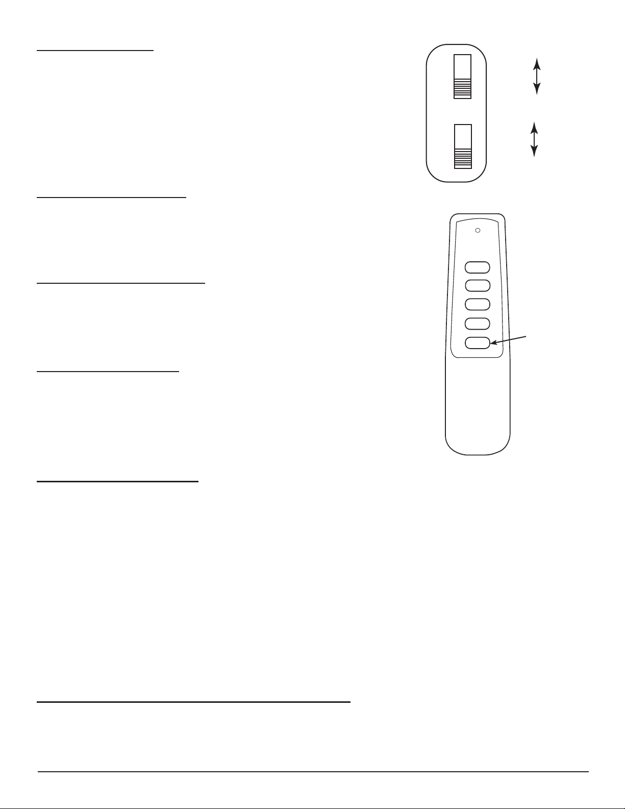
Fig. 20 Valve box switches
Fig. 21 Remote control
Continuous button
2. REMOTE CONTROL FEATURE:
The AFVK-SP, AFVK-SP-HL, or AFVK-SP-MHL comes with a remote control transmitter. This remote is already
programmed to operate your valve kit directly out of the box.
The valve kit module has a built in remote control receiver that allows the user to program a hand held remote transmitter
to the appliance at any time during or after installation of the appliance.
1. There is a switch located on the front of the valve kit face plate that reads OFF/REMOTE. See Fig. 20.
2. When the OFF/REMOTE switch is in the OFF position the valve kit will operate from the rocker switch in the center of
the face plate. Note: Fig. 13 page 6 (“O” is Off and “I” is for Ignite)
3. When the OFF/REMOTE switch is in the REMOTE position the appliance will operate from the Remote Control
transmitter. Note: The valve kit module must be programmed to the Remote Control transmitter.
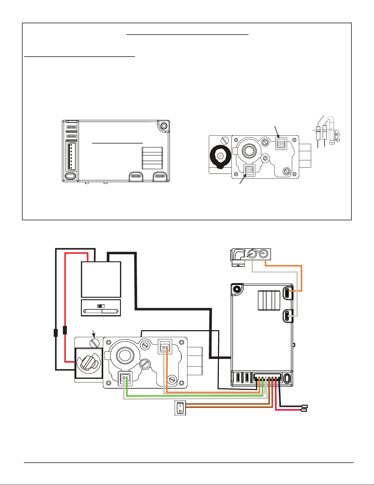
4. If needed, program the module (Make sure the batteries have been installed in the battery pack). Locate the learn
button on the module (See Fig. 14). Press and release the learn button there will be a beep sound from the
module. Then press any button on the remote transmitter. Once the modules internal receiver accepts the
transmitter code, there will be a series of rapid beeps.
5. The remote system is ready for use.
MAINTENANCE OF YOUR AFVK-SP SERIES VALVE KIT SYSTEM
1. Your system should be checked once a year (At the start of the heating season) for proper operation by a qualied
service representative.
2. Replace all batteries at the start of the season. Items to check: electronic valve operation, Spark to pilot operation,
ON/OFF switch operation, damper operation, visual check of the burner and gas connections for leaks.

American Flame AFVK-SP Valve Kits REV. 10-8-19 Page 10
FOR YOUR SAFETY READ BEFORE LIGHTING
WARNING: IF YOU DO NOT FOLLOW THESE INSTRUCTIONS EXACTLY, A FIRE OR EXPLOSION MAY RESULT
CAUSING PROPERTY DAMAGE, PERSONAL INJURY OR LOSS OF LIFE.
1. This installation should be installed with provisions for combustion and ventilation air, must conform with local codes
or in the absence of local codes to the national fuel Gas Code ANSI Z223 latest addition.
2. This product must be on a gas supply line that is less than 1/2 psi. and an individual manual shut-off.
3. Never operate this new system with the glass replace enclosures (doors) in the closed position.
4. Connecting 120-volt electrical power to a valve kit directly will cause damage and will void warranty. An optional AF-
4000ADP24 adapter (step-down transformer 120VAC to 7.5VDC) can be installed to eliminate batteries. The battery
pack must remain connected to enable the solenoid or motor drive operation however the batteries can be removed.
NOTE: VALVE BOX MUST BE LOCATED A MINIMUM OF 2-INCHES FROM SIDES OF THE BASKET GRATE AND
NEVER PLACED DIRECTLY IN FRONT OR BEHIND THE BASKET GRATE
OPERATING PROCEDURE
After installation is completed follow these steps to operate the AFVK-SP.
1. Turn ON the main gas supply and check all ttings and connections for leaks with soap and water solution.
2. Move the OFF/REMOTE slide switch on the face plate of valve box to the REMOTE position. See Fig. 20. Push the
ON button on the remote transmitter this will start the ignition system. The pilot will begin to spark and then light. Once
the pilot is lit 2 seconds the main burner will light.
3. Adjust the main ame from HI to LO with the manual HI/LO knob on front of valve kit.
Note: Move the OFF/REMOTE slide switch on the face plate of valve box to the OFF position then push the rocker switch
to the “I” position this will manually start the ignition system. Once the pilot is lit 2 seconds the main burner will light.
After the installation is complete follow these steps to operate the AFVK-SP-HL & AFVK-SP-MHL
1. Turn on the main gas supply and check all ttings and connections for leaks with soap and water solution.
2. Move the OFF/REMOTE slide switch on the front to the REMOTE position. See Fig. 12. Push the ON button on the
remote transmitter position this will start the ignition system. The pilot will begin to spark and then light once the pilot
is lit 2 seconds later the main burner will light.
3. Adjust the main ame from HI to LO with the HI/LO buttons on the remote transmitter.
Note: Move the OFF/REMOTE slide switch on the face plate of the valve boxto the OFF position then push the rocker
switch to the “I” position this will manually start the ignition system. Once the pilot is lit 2 seconds the main burner will
light.
Note: On the AFVK-SP-H/L press and release the LO button and the ame will go to LO. Press and release the HI button
and the ame will go to HI.
Note: On the AFVK-SP-MH/L press and hold the LO button and the ame will modulate to LO. Press and hold the HI
button and the ame will modulate to HI.
Note: On initial start up: due to air in the gas supply line it may take an extended amount of time for the pilot to light.
There is a 60 second lockout built into the module. To reset turn the rocker switch OFF then ON or push the OFF button
on the remote transmitter then push the ON button.

American Flame AFVK-SP Valve Kits REV. 10-8-19 Page 11
TROUBLESHOOTING
IMPORTANT: An experienced qualied service technician should only perform troubleshooting procedures.
PILOT WILL NOT STAY LIT:
1. Conrm that the “S” sensor wire and the “I” igniter wires are properly connected to the module “S” and “I” terminals on
the module. Note: Figs. 11 & 13 on page 6 for terminal locations.
2. Conrm that the Spark to Pilot burner is properly grounded to the gas control valve (Ground is provided through the
pilot tubing).
3. Check the ground wire from the module to the gas control valve (Black ground wire on the 8 pin connector)
4. Check the power source battery pack connections and voltage of batteries.
5. Optional check the position of the CONTINUOUS PILOT switch on the valve kit module. See: Fig. 20
CONTINUOUS PILOT SHUTS OFF AFTER A PERIOD OF TIME
1. If the control module is set in the Continuous Pilot mode (either manually or by remote control), a 7-day countdown
timer will be started. After 7-days if the main ame has not been turned ON, the control module will turn the pilot OFF.
If the main ame is turned ON during the 7-day countdown, the timer is reset and the cycle restarted again.
2. When continuous pilot is turned OFF, simply press the ON button on the remote control or press the rocker switch to
ON to light the system in a normal fashion. The 7-day timer will reset unless you turn the continuous pilot switch to
the OFF position.
MAIN BURNER DOES NOT COME ON WHEN THE MANUAL ROCKER SWITCH OR REMOTE CONTROL IS TURNED
ON:
1. Conrm that the pilot sparks and lights.
2. Check the (2) pin plastic connectors that plug in the face of the gas control valve. See Fig. 13.
3. Conrm that the gas control valve is properly grounded to the valve kit module.
REMOTE WON’T OPERATE VALVE KIT
1. Ensure the module switch is in Remote position and check batteries in the remote and the battery pack.
2. Clear Codes: Memory in the module might be full if the learn button is pressed too many times. If this happens no
audible beep will be heard. To clear memory, place the module slide switch into the REMOTE position. Press the
learn button and release after 10 seconds. You should hear three (3) long audible beeps indicating all codes have
cleared. You can now “relearn” the transmitter to the module as described below.
3. Press the LEARN button on the module to accept the transmitter security code. Ensure the slide button on the
module in the REMOTE position; the module will not LEARN if the slide switch is in the OFF position. The LEARN
button is located on the side of the module (See gure 10). Using the end of a paperclip or toothpick gently press
and release the black LEARN button inside the hole. When you release the LEARN button the module will emit an
audible “beep”. After the module emits a beep press the transmitter ON button and release. The module will emit
several beeps indicating that the transmitter’s code has been accepted into the module then you can presume normal
operation.

American Flame AFVK-SP Valve Kits REV. 10-8-19 Page 12
Replacement Parts
Item # Description Part #
1Complete Pilot Assembly 238577-13
2 Gas Valve Only for AFVK-SP AF-4014
2a Gas Valve Only for AFVL-SP-HL AF-4024
2b Gas Valve Only for AFVK-SP-MHL AF-4034
3 Control Module AF-4000MOD-1
4 Battery Pack Heat Shield RS-1A
5 Battery Pack AF-4000BP
6 10” Flex Gas Line T102-9898-10
7 Damper Clamp 685-14
83/8” to 1/2” ared adapter UR3-68
9 Remote control used on AFVL-SP-HL & AFVK-SP-MHL SP1001H-LTX
10 Remote control used on AFVK-SP SP1001-TX
11 3/8” Flare x 3/9” NPT Connector U1-6C-S
12 8-Pin wire harnes for all valve kits (not shown) AF-40008PIN6WH
13 1-inch Manual Extension Knob for AFVK-SP (not shown) AF-2000H-L-1
ON
OFF
HI
LO
PILOT
Continuous
Latching Solenoid DC Motor Drive
ON
ON/OFF
Continuous Pilot
OFF
1
2
3
4
5
67
8
9
Remote/Off
S
I
IPI
POWER
Learn
Continuous
Pilot
Off/On
AUX
OUT
PILOT ADJ
IN
MAIN
PILOT
10 11
LIMITED WARRANTY
American Flame warrants the AFVK-SP, AFVK-SP-HL, or AFVK-SP-MHL Valve Kit for 12 months from the date of purchase or
installation to the original purchaser to be free from defects in materials and workmanship. Damage to the AFVK-SP, AFVK-SP-HL, or
AFVK-SP-MHL Valve Kit caused by accident, misuse, abuse, or installation error, whether preformed by a contractor, Service
Company, or owner, is not covered by this warranty. American Flame will not be responsible for labor charges and/or damage incurred
in installation, repair, replacement, or for incidental or consequential damage. Some states, provinces, and nations do not allow
exclusion or limitations of incidental or consequential damages, so the above limitations or exclusions may not apply. This warranty
gives you specic legal rights. You may also have other rights that vary by state, province, or nation
FOR TECHNICAL QUESTIONS, CALL:
Support Sales: (888) 699-6167
www.skytechpg.com
9230 Conservation Way, Fort Wayne, IN 46809
(855) 498-8324
This manual suits for next models
2
Table of contents
Other american flame Control Unit manuals
Popular Control Unit manuals by other brands

Applied Motion Products
Applied Motion Products STAC6 Series Hardware manual

System Sensor
System Sensor M500FP Installation and maintenance instructions

Hogfors
Hogfors 31300CS Series Installation and operation manual

BETTE
BETTE BETTESENSORY B631 manual

Vizmo
Vizmo VIZMONET RJ-2002 user manual

Anritsu
Anritsu MU120119A Operation manual