Product names listed herein are trademarks of American Standard Inc.
American Standard Inc. 1
C43168A
HANDSHOWER INSTALLATION (Model 3901 & 3941 series only)
SERVICE
6
3
CARTRIDGE
SCREEN
SPRING
CLIP
STOP
WASHER
TEST INSTALLED FAUCET
4Turn VALVES "off" and attach handles. See separate "Instruction
Sheet" for assembly of handles.
Lift HANDSHOWER from HOLDER, direct spray into tub, lift
TRANSFER KNOB to check HANDSHOWER and HOSES for leaks.
Turn handles "off."
To change direction of handle rotation,
proceed as follows:
Turn valve to OFF position.
Remove INSERT and HANDLE SCREW.
Slip HANDLE with ADAPTER off.
Remove SPRING CLIP.
Lift STOP WASHER, turn 0° and replace.
Replace SPRING CLIP.
Replace ADAPTER, HANDLE, SCREW, and
INSERT.
Plastic SCREEN in CARTRIDGE may accumulate
dirt causing reduced water flow. To clean, first
turn off hot and cold water supplies, then:
Remove HANDLE (see above).
Unscrew CARTRIDGE with wrench.
Thoroughly rinse plastic SCREEN at
base of CARTRIDGE.
Replace CARTRIDGE until flange is
tight against valve body.
Turn valves OFF.
Replace ADAPTER, HANDLE, SCREW,
and INSERT.
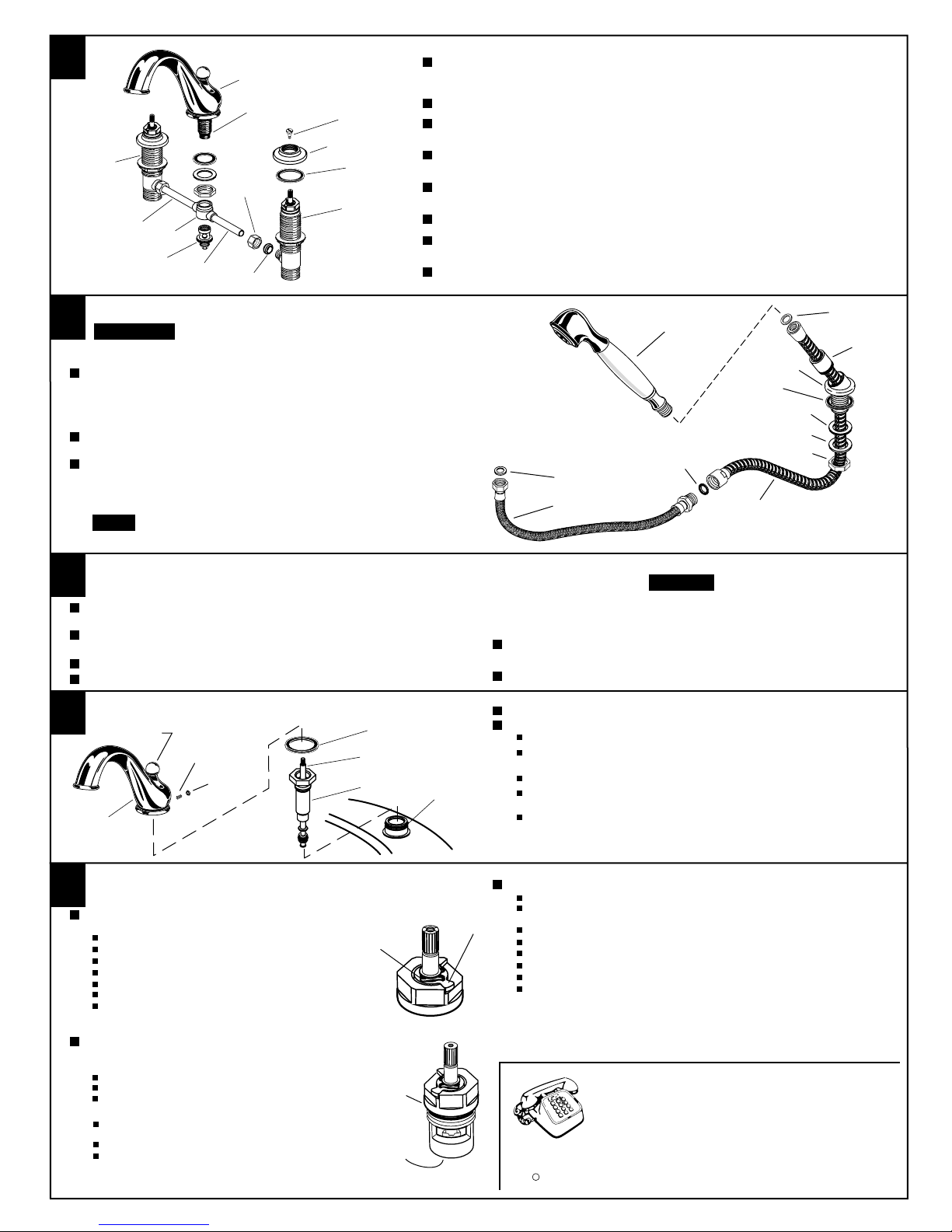
HANDSHOWER
SPOUT
HANDLE
SCREW
ESCUTCHEON
RUBBER
RING
VALVE
FERRULE
COUPLING
NUT
TUBE &
TEE ASSEMBLY
COUPLING
TEE
TUBING
VALVE
Prepare TUBE and TEE ASSEMBLY to fit existing VALVE location (between 6-1/2"
and12"). If necessary, cut and/or bend TUBING carefully. Make sure tube bend
is close to the TEE so that it will not effect the compression joint at the VALVE.
Remove COUPLING NUT and FERRULE from each VALVE and slide onto TUBING.
Push TUBING ends into VALVE side outlets. Insert VALVES into mounting holes
from underside of ledge.
Press TEE onto SPOUT SHANK making certain that the O-RING is properly seated
on SHANK.
Place RUBBER RING into ESCUTCHEON and screw ESCUTCHEON onto valve until
snug against internal stop.
Tighten LOCKNUT to secure VALVE position. Attach COUPLING to TEE and tighten.
Slide FERRULE and COUPLING NUT to outlet of VALVE and tighten COUPLING NUT
firmly.
Connect HOT water supply to inlet of left VALVE and COLD water supply to inlet of
right VALVE using appropriate connector.
2
SEAL
WASHER
HOSE
SEAL
WASHER LOCKNUT
WASHER
RUBBER
WASHER
RUBBER
RING
SHOWER
ESCUTCHEON
SEAL
WASHER
SHOWER
HOSE
HOLDER
Check with loc l codes, nd if required, dd v cuum bre ker
kit (p rt no. 028708) t specified height. Refer to the inst l-
l tion instructions supplied with the kit.
IMPORTANT
Drop ESCUTCHEON through the fourth hole of the tub ledge (12" max from SPOUT
center) with HOLDER directed towards tub center. Be sure RUBBER RING is properly
seated in ESCUTCHEON. Attach RUBBER WASHER and BRASS WASHER from
underside of ledge. Secure
ESCUTCHEON by tightening locknut.
Add SEAL WASHER and connect HOSE to outlet nipple on bottom of
COUPLING. Tighten firmly.
Unscrew HOLDER from ESCUTCHEON. Slip SHOWER HOSE
with COUPLING NUT through HOLDER and ESCUTCHEON. Install
SEALS and connect both HOSES, attach HOLDER to ESCUTCHEON
and connect HANDSHOWER.
When not in use, HANDSHOWER should be se ted
in the HOLDER.
NOTE
To replace SHOWER HOSE, proceed as follows:
Disconnect HANDSHOWER.
Unscrew HOLDER and pull SHOWER HOSE until hose coupling
appears.
Prevent HOSE from slipping back (use clamp, tape, etc.)
Disconnect SHOWER HOSE.
Remove HOLDER from old HOSE and slip over new SHOWER HOSE.
Insert new SEALS and connect HOSES and HANDSHOWER.
Open valves, lift transfer knob and check for leaks.
Release HOSE, screw HOLDER back to ESCUTCHEON, and seat
HANDSHOWER.
SET
SCREW
PLUG
BUTTON
RUBBER
RING
TRANSFER
ROD
SHANK
SLEEVE
SPOUT
SHANK
Before the b throom is completely finished, you m y
w nt to remove spout, h ndshower, nd h ndles. To remove handles, see separate "Instruction Sheet."
To remove SPOUT, proceed as follows:
Lift TRANSFER ROD and unscrew KNOB. (Model 3 01 & 3 41 only).
Remove PLUG BUTTON and remove SET SCREW using hex wrench
supplied.
Lift SPOUT off SHANK carefully and remove RUBBER RING.
Unscrew SHANK SLEEVE and lift TRANSFFER ROD from
SHANK (Model 3 01 & 3 41 only).
Reverse sequence to re-install SPOUT. Be sure RUBBER
RING is properly seated in its recess at the base of the SPOUT.
Make certain SET SCREW is properly aligned and tight so that
SPOUT is locked in place.
5
With handles in "off" position, turn on water supplies and check
all connections for leaks.
Operate both handles and flush water lines thoroughly.
Check SPOUT mounting for leaks.
The flow r te of this Tub Filler exceeds 20 g llons/minute
t higher w ter pressure. Do not fill b thtub un ttended.
CAUTION
KNOB
O-RING
HOTLINE FOR HELP
For toll-free information and answers to your questions, call:
1 (800) 223-0068
Weekdays 8:00 a.m. to 7:00 p.m. Eastern Time
Saturdays 8:00 a.m. to 4:00 p.m. Eastern Time
IN CANADA 1-800-387-036 (TORONTO 1-416-536-560 )


