AmeriGlide Victorian Outdoor Elevator User manual

Victorian Outdoor Elevator
Please read this installation
guide carefully to ensure
correct installation of your
Victorian Outdoor Elevator.
Installation Guide

Table of Contents
Disclaimers and Important Information ...............................................................................................................................
Before you Get Started - Checklist ..........................................................................................................................................
Installing Your Victorian Outdoor Elevator ...........................................................................................................................
Step 1: Unboxing ...............................................................................................................................................................
Step 2: Install Upper Support Brace ..............................................................................................................................
Step 3: Install Rail Support Brackets ..............................................................................................................................
Step 4: Position and Align Sill Plate and Car Sling .......................................................................................................
Step 5: Attach Lower Rail Sections .................................................................................................................................
Step 6: Attach Upper Rail Section Joining Plate ............................................................................................................
Step 7: Attach Upper Rail Sections .................................................................................................................................
Step 8: Lateral Rollers (Top and Bottom) ......................................................................................................................
Step 9: Properly Align the Rail Assembly ......................................................................................................................
Step 10: Disassemble Motorized Unit ...........................................................................................................................
Step 11: Attach Motor Plate ............................................................................................................................................
Step 12: Reattach Motor Block .......................................................................................................................................
Step 13: Install the Batteries ...........................................................................................................................................
Step 14: Battery Chargers ................................................................................................................................................
Step 15: Wire the Batteries ..............................................................................................................................................
Step 16: Level and Secure the Winding Drum .............................................................................................................
Step 17: Wire Motor and Power Supply Cable .............................................................................................................
Step 18: Traveling Cable Installation ..............................................................................................................................
Step 19: Winding Drum Cable Installation ....................................................................................................................
Step 20: Winding Drum Cable Connections .................................................................................................................
Step 21: Winding Drum Cable Wedge Sockets ............................................................................................................
Step 22: Upper Limit Switch Cam .................................................................................................................................
3
7
8
8
9
9
10
11
12
13
14
15
16
17
18
19
19
20
21
22
23
24
25
26
27
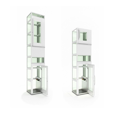
Table of Contents
Step 23: Install Upper Landing Gate ..............................................................................................................................
Step 24: Wire Upper Landing Call Station and Interlock ............................................................................................
Cab Assembly ................................................................................................................................................................................
Step 1: Install the Floor on the Car Sling .......................................................................................................................
Step 2: Install the COP Wall .............................................................................................................................................
Step 3: Install the Opposite Wall .....................................................................................................................................
Step 4: Install the Roof ......................................................................................................................................................
Step 5: Install the Rear Lexan Wall of the Cabin ..........................................................................................................
Step 6: Install the Cabin Bottom Track on the Floor ...................................................................................................
Step 7: Install the Upper Track for the Cabin Gate ......................................................................................................
Step 8: Panel Insertion ......................................................................................................................................................
Step 9: Install Mid-Panel Slot Catches ............................................................................................................................
Step 10: Install the Screws that will Allow the Doors to Slide in Accordion ............................................................
Step 11: Setting Travel Stops ...........................................................................................................................................
Step 12: Install the Handrail ............................................................................................................................................
Step 13: Pass the Electrical Wires Coming from the Control Panel into the Car Sling ..........................................
Step 14: Install the Interlock at the Bottom of the Cab the Opposing Side of the Rail .........................................
Before Leaving the Job Site ........................................................................................................................................................
089_Victorian ODE Install Guide_AMG__1122
28
29
30
30
30
30
30
31
31
31
32
34
35
35
36
36
36
37

AmeriGlide shall not be held responsible or liable for any personal injury or property damage caused by or resulting from
inappropriate operation of original product or of a product that has been modied or altered from the original design. No
person or company is authorized to change the Victorian Outdoor Elevator design without authorization and the express
written consent of AmeriGlide.
Do not throw away, destroy, or lose this installation guide. The instructions included in this guide must be followed to
prevent product malfunction, property damage, injury, or death to the user or other people. Incorrect operation due to
ignoring instructions found in this guide can cause harm, damage, injury or death. A summary of safety precautions is
found below.
For more technical materials such as drawings and specication, end user support, and manuals, visit AmeriGlide.com
Important
Read all instructions contained in this installation guide before installing the Victorian Outdoor Elevator. It is highly
recommended to observe and adhere to all governing codes and ordinances in the job site locale. This includes ensuring
all work and materials comply and conform with all authorities having jurisdictions. Proper installation is the responsibility
of the installer and failure to follow all instructions renders the AmeriGlide Limited Warranty null and void.
Warning
Safety of personnel is the primary concern during all procedures. Before beginning installation, read and understand the
installation guide and containing procedures carefully to ensure correct and safe installation. Use the appropriate tools
and accessories during installation. Plan your work and do not work alone, if possible. Know how to obtain emergency
medical and re ghting assistance.
Be sure to follow all the precautions on the next page as they are important for ensuring safety. This installation guide
classies the safety precautions into DANGER, WARNING, CAUTION and NOTE.
Safety Precautions
Disclaimers and Important Information
3

The Victorian Outdoor Elevator shall be installed and serviced by an authorized AmeriGlide dealer only. The authorized
dealer should refer to this guide for installation and servicing. For maintenance, please refer to the Owner’s Manual.
Please carefully read and follow the instructions found in this guide BEFORE installing and/or operating the Victorian
Outdoor Elevator. Improper installation, adjustment, service, use or maintenance can cause personal injury or property
damage. If you have any problems or need assistance please contact your dealer immediately.
Important for the Installer
DANGER Indicates an imminently hazardous situation which, if not avoided, will result in
death or serious injury.
WARNING Failure to follow any of WARNING is likely to result in such grave consequences as
death or serious injury.
CAUTION Failure to follow any of CAUTION may in some cases result in grave consequences.
NOTE Provides information such as reminders and guidelines and do not t into the
preceding text.
!
!
!
!
The Victorian Outdoor Elevator has been designed to meet CSA B613/B355 and ASME 18.1 standards. Code requirements
and standards for vertical platform lifts vary depending on location and region. It is the installer’s responsibility to contact
their local code enforcement oce and determine all of the regulations they are subject to. You must do this before
installing the Victorian Outdoor Elevator.
Codes and Regulations
4

The Victorian Outdoor Elevator must only be installed on an approved pad or oor that has adequate drainage and meets
local codes, standards and regulations. In addition, there must be adequate lighting and sucient headroom above the
lift. Please refer to and verify with the Technical Drawings before beginning the install.
Site Requirements
The Victorian Outdoor Elevator requires a 110VAC-20 AMP grounded electrical circuit and a GFCI protected circuit.
Depending on local codes and regulations, this connection may need to be routed in electrical conduit and hard-wired.
Electrical Requirements
Installation Safety Instructions
• Never exceed the maximum rated lift capacity.
• Never use the Victorian Outdoor Elevator to lift freight
or other materials than intended by design.
• Read and understand the installation guide prior to
installing the Victorian Outdoor Elevator.
• Wear appropriate safety protection equipment for
your head, eyes, hands and feet during all phases of
the installation.
• Use extreme caution when lifting components into
position to avoid personal injury and damage to
the equipment.
• Keep panels and protective coverings in place to avoid
potentially fatal injury.
• Disconnect power from the unit before performing
any electrical or mechanical service operations.
WARNING
!DO NOT OPERATE OR RIDE ON THE LIFT UNTIL IT HAS BEEN ANCHORED TO AN APPROVED
PAD OR FLOOR.
WARNING
!To reduce the risk of re, electric shock, personal injuries, and/or death, obey the
following precautions:
5

• Never bypass sensor switches which prevent accidental
start up when protective panels are removed.
• Be aware of the location of others in the work zone.
• Do not wear jewelry or loose clothing.
• Use only recommended anchor fasteners.
• Lock the wheels of any mobility device riding
on the platform.
• Check and verify for applicable local codes
and regulations.
NOTE
!
Failure to comply the these Installation Safety Instructions could render the AmeriGlide
Limited Warranty null and void. If you have any question or concerns that are not covered
in this installation guide, please contact your dealer immediately.
6

Before You Get Started - Checklist
1. Understand your client’s intended use of the lift.
2. Determine the local code and regulations requirements.
3. Upon receipt of the Victorian Outdoor Elevator, verify the lift for shipping damage
immediately. Report any discrepancies or damage claims to your dealer.
4. Verify site parameters, technical drawings and all preparatory work prior
to installation.
5. Plan and prepare for all electrical requirements.
7

Installing the Victorian Outdoor Elevator
Step 1: Unboxing
• Remove box cover.
• Inspect for damage (ie. take damaged photos).
• Remove boxes and cabin parts and set them aside.
• Move components to the installation area.
8

Step 3: Install Rail Support Brackets
• Small Triangle Rail Support Brackets
• 2 x 1/2” - 13 Flathead
• Large Triangle Support Bracket
• 6 x 3/8” - 16 Bolts
Materials
Materials
Install
Install
Step 2: Install the Upper Support Brace
• Attach the Large Triangle Brace to the upper landing with
6 X 3/8” - 16 Bolts provided.
• Install the brace with the longest straight side 14 3/16”
from the side of the upper landing entrance door/gate.
• Attach the Small Triangle Rail Support Brackets to
the main Triangle Support Bracket with 2x 1/2 - 13
Flathead Bolts.
9

Step 4: Position and Align Sill Plate and Car Sling
• Bottom Sill Plate
• Car Sling Assembly
Materials
Install
• Position the Bottom Sill Plate below the Large Support
Bracket. DO NOT ATTACH SILL PLATE AT THIS TIME.
• Position the Car Sling Assembly approximately 6” over
the Bottom Sill Plate using blocks or a jig in order to leave
space to attach Bottom Rails to the Sill Plate.
10

Step 5: Attach Lower Rail Sections
• Bottom Rail Sections
• 8 x 1/2” - 13 Bolts, 8 x Ea. 1/2” Washers, Lock washers, 8 x 1/2” Nuts
Materials
Install
• Locate the Bottom Rail Sections. Lower Rail Sections will
always be longer than the Upper Rail Sections.
• One side at a time, slide the Bottom Rail Sections on each
side of the Car Sling Assembly.
• Bolt to the Bottom Sill Plate using the supplied 1/2” bolts,
washers and lock washers as shown.
CAUTION
!HEAVY PARTS
The Rail Sections are quite heavy. Use Caution.
21 3
11

Step 6: Attach Upper Rail Section Joining Plate
• Joining Plates
• 8 x 1/2” - 13 Bolts, 8 x Ea. 1/2” Washers, Lock washers
8 x 1/2” Nuts
Materials
Install
• This step should be completed with the rails on the
ground for ease of installation, as the Rail Sections are
quite heavy.
• One side at a time, attach Joining Plates to each Upper
Rail Section with supplied hardware, as shown. Properly
tighten bolts.
12

Step 7: Attach Upper Rail Sections
DANGER
!
USE PROPER AND SECURE SCAFFOLDING.
FAILURE TO DO SO MAY RESULT IN SERIOUS
INJURY OR DEATH.
• Upper Rail Sections
• Mounting Hardware
Materials
Install
• One side at a time, attach Upper Rail
Section to Lower Rail Section with
supplied hardware, as shown. Properly
tighten bolts.
• Attach each Upper Rail Section to the
corresponding Small Triangle Support
Bracket.
• Ensure that all Triangle Brackets are
level before nal tightening the bolts.
• After the Rail Sections are attached, use
a tape measure to conrm Rails are in
parallel.
13

Step 8: Lateral Rollers (Top and Bottom)
Install
• Tighten the 4 Lateral Rollers (2 at top, 2 at bottom).
14

Step 9: Properly Align the Rail Assembly
Install
• Using a long level, ensure that both rails are
plumb, level and have remained parallel.
• Mark the position of the Bottom Sill Plate and
pre-drill bolt locations into the concrete pad.
• Use Proper Hardware to Attach the Sill Plate to
the concrete pad.
TIP: Use a pry bar and a mallet to
gently move the rail assembly into
the correct position.
TIP: To gain proper
access for the drill,
lift the Car Sling,
and support with a
scrap piece of 2x4.
• 8 x Anchor Bolts; 1/4” - 2”
Materials
15

Step 10: Disassemble Motorized Unit
Install
• Unscrew the 6 bolts holding the motor block to
the Top Plate (3 bolts on the front and 3 on the
back).
• Remove the motor block (motor, drum,
gearbox) to make this piece lighter.
16

Step 11: Attach Motor Plate
Install
• Attach the Motor Plate to the Upper Rail
Sections using the 8 supplied 1/2” Bolts,
Washers, Lock Washers and Nuts (4 per side).
DANGER
!
USE PROPER AND SECURE SCAFFOLDING.
FAILURE TO DO SO MAY RESULT IN SERIOUS
INJURY OR DEATH.
• Bottom Rail Sections
• 8 x 1/2” - 13 Bolts, 8 x Ea. 1/2” Washers,
Lockwashers, 8 x 1/2” Nuts
Materials
17

Step 12: Reattach Motor Block
Install
• Reattach the Motor Block to the Motor Plate
with the 6 bolts previously removed.
DANGER
!
USE PROPER AND SECURE SCAFFOLDING.
FAILURE TO DO SO MAY RESULT IN SERIOUS
INJURY OR DEATH.
18

Step 13: Install the Batteries
Step 14: Battery Chargers
Install
Install
• Install both Batteries with the Terminals facing
the outside of the unit, as shown.
• Plug In the chargers to the appropriate
terminals, and attach (stick) the charger bodies
to the front face of the batteries, as shown.
19
Table of contents