AmeriGlide Escort User manual

Read and understand this manual thoroughly before attempting to install or operate the lift. If you have any questions,
please contact your Authorized AmeriGlide Dealer or AmeriGlide's Technical Service Department at 866-294-4460.
P 866-294-4460 | www.ameriglide.com
Escort Stair Lift
Installation Manual

AmeriGlide | www.ameriglide.com | 866-294-4460
2Escort Stair Lift Installation Manual
Table of Contents
READ AND UNDERSTAND
THIS MANUAL PRIOR TO
INSTALLATION OR OPERATION.
Please read, follow, and fully understand the
installation section of this manual before beginning.
Knowing the lift's adjustments and becoming
familiar with tips for proper installation will not only
save you time and energy, but also help you avoid
possible injury. If you do not understand any portion
of installation or operation, please consult our
technical service department at 866-294-4460.
INSTALLATION & APPLICATION NOTES 3
PREPARATION 411
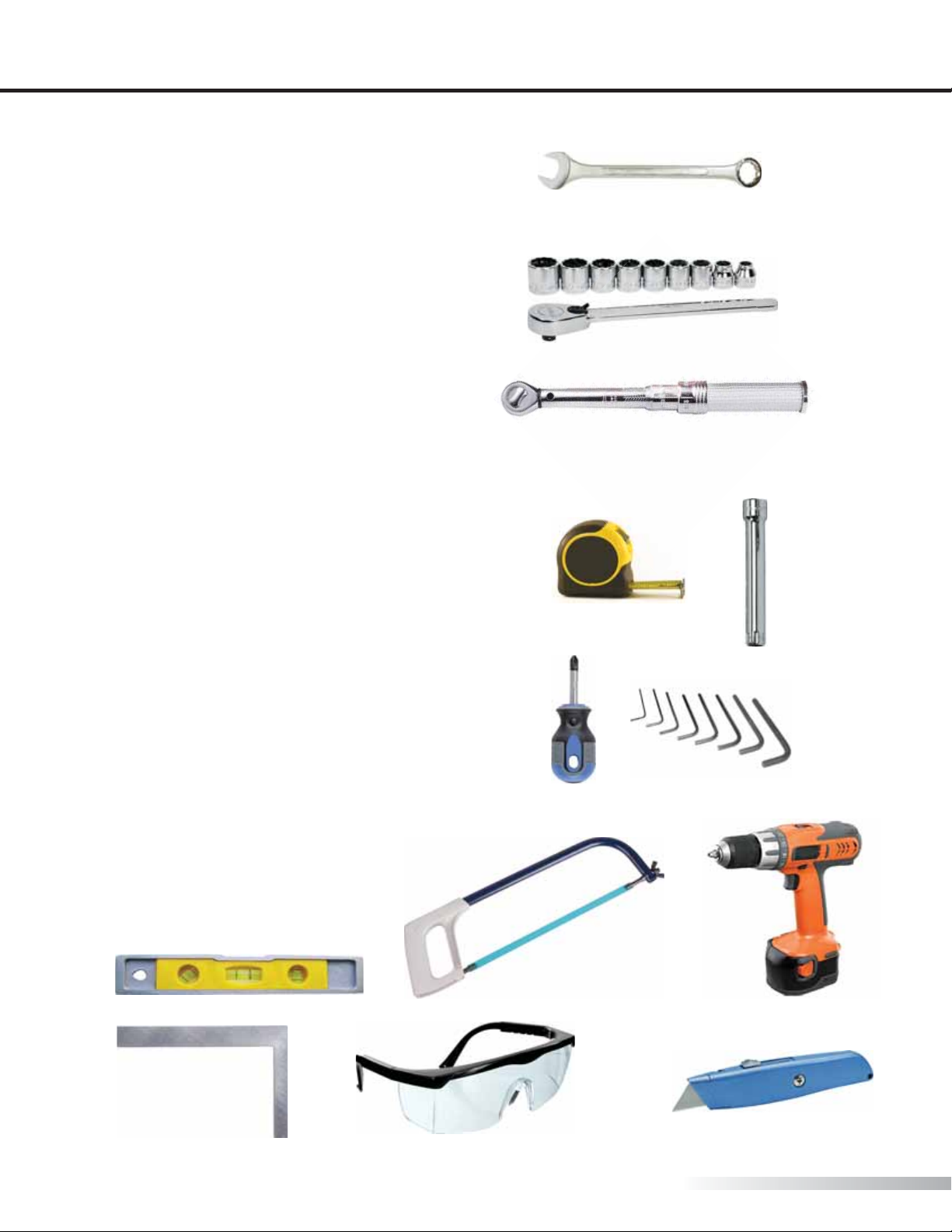
Tool Checklist. . . . . . . . . . . . . . . . . . . . . . . . . . . . 4
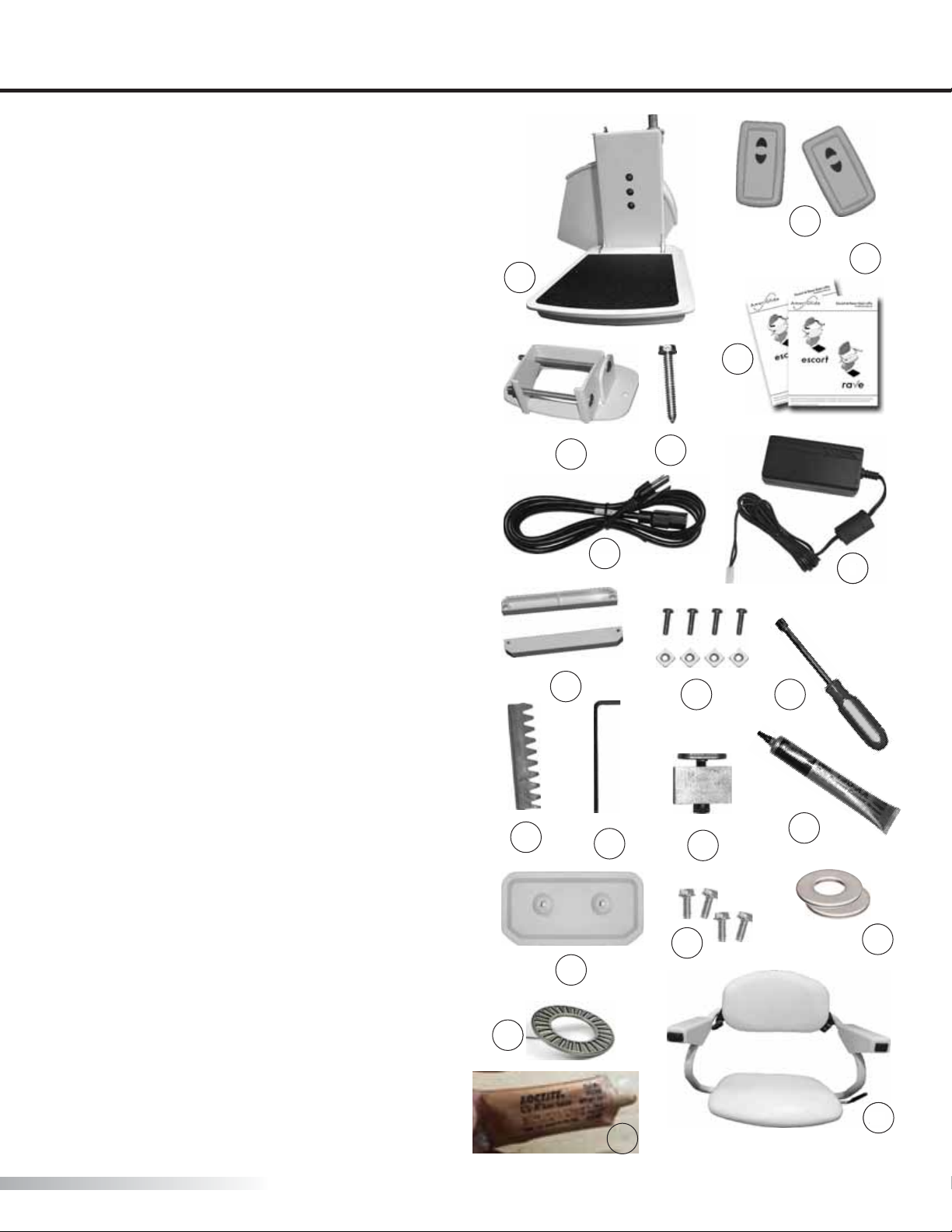
What's In the Box . . . . . . . . . . . . . . . . . . . . . . . . 5
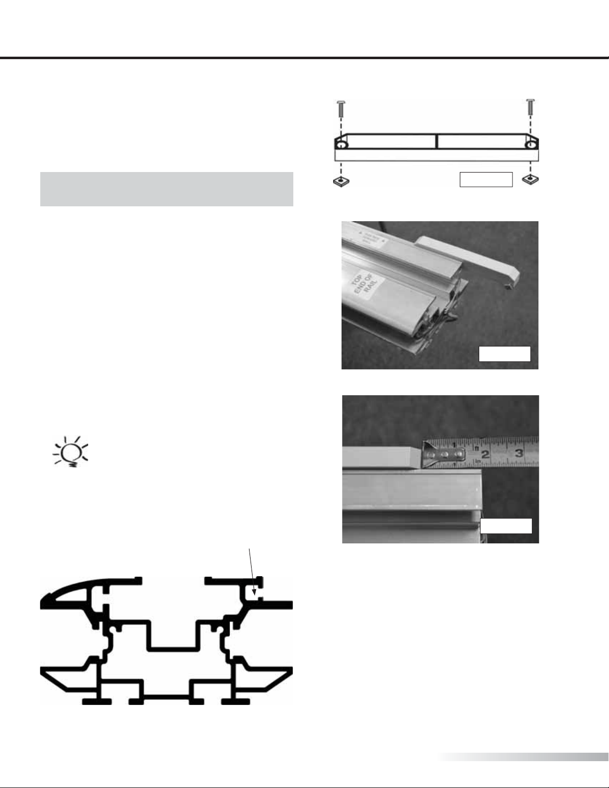
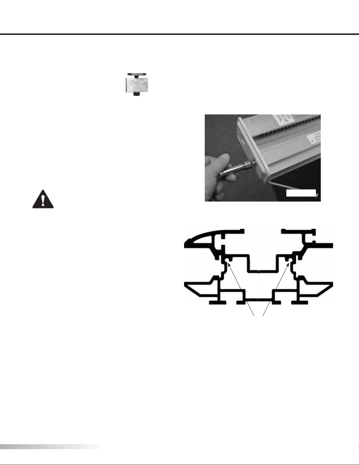
Getting to Know the Rail . . . . . . . . . . . . . . . . . 6
Preparing the Rail. . . . . . . . . . . . . . . . . . . . . 7-11
INSTALLATION 1221
Installing the Rail . . . . . . . . . . . . . . . . . . . . . . . 12
Installing the Chassis. . . . . . . . . . . . . . . . . 13-15
Installing the Chair. . . . . . . . . . . . . . . . . . . 16-17
Re-installing the Charging Strips . . . . . . . . 18
Installing the Upper Limit Cam . . . . . . . . . . 19
Installing the End Cap/Bracket Cap Option20
Charging System . . . . . . . . . . . . . . . . . . . . . . . 21
Completion Checklist . . . . . . . . . . . . . . . . . . . 22
VERIFYING OPERATION 23
REQUIRED MAINTENANCE 2425
AUDIO ALERT 26
REMOTE CONTROL PROGRAMMING 27
MANUAL LOWERING TOOL 28
APPENDIX I 29
Measuring the Rail . . . . . . . . . . . . . . . . . . . . . . 30
Flight Angle Charts . . . . . . . . . . . . . . . . . . . . . . 31
Cutting the Rail . . . . . . . . . . . . . . . . . . . . . . 32-34
APPENDIX II 3538
Cutting the Gear Rack. . . . . . . . . . . . . . . . . . . 36
Adjusting the Gear Rack. . . . . . . . . . . . . . 37-38
SERVICE NOTES 39
INDICATIONS OF USE STATEMENT
The Escort Stair Lift assists with the transfer of
patients or mobility impaired persons, up and down
between levels of a residential or private facility.
SYMBOLS USED IN THIS MANUAL
READ MANUAL - Pay close attention to
the instructions in the manual.
CAUTION - Hazardous situation. If not
avoided, could result in serious damage
to property.
WARNING - Hazardous situation. If not
avoided, could result in serious injury to
installer or user.
SHOCK HAZARD - Disconnect from
power source to avoid personal injury.
HEAVY - Be sure to have help available to
avoid back injury.
TIP - Helpful tips that will facilitate ease
of installation.
CHECK - Reminder to check certain
portions of installation before continuing.

Escort Stair Lift Installation Manual 3
TEC0016 20160714 P/N: 630-00039 Rev C
Application Notes
INSTALLATION AND APPLICATION NOTES
INCLINE
The maximum inclination (angle) the Escort lift can be installed is 45 degrees.
The minimum inclination (angle) the Escort lift can be installed is 25 degrees.
MAXIMUM RAIL LENGTH
32 Feet
LOAD CAPACITY
The maximum load capacity is 300 lbs.
The lift is not to be used to transport cargo.
ELECTRICAL POWER SUPPLY REQUIREMENTS
A dedicated 120 VAC 15A 60Hz, 3-wire grounded outlet. NEC requirement.
Electrical equipment shall be certied to the requirements of CAN/CSA B44.1/ASME A17.5.
ASME 18.1 REQUIREMENTS INSTALLATION REGULATIONS
The Escort lift is an incline stairway chair lift for private residence use only.
Installation of this lift must comply to the following American Society of Mechanical Engineers ASME 18.1 – 2011
"safety standard for platform lifts and stairway chair lifts".
• 7.1.1 The structure on which the equipment is installed shall be capable of safely supporting the loads
imposed.
• 7.1.2 The installation of all electrical equipment and wiring shall conform to the requirements ANSI/NFPA
70.
• 7.6.4 At no point in its travel shall the edge of the footrest facing the upper landing be more than 24 in.
above the step or landing as measured vertically.

AmeriGlide | www.ameriglide.com | 866-294-4460
4Escort Stair Lift Installation Manual
TOOL CHECKLIST
Preparation
PREPARATION
TOOL CHECKLIST
1/2 inch Combination Wrench
3/8" Ratchet with 1/4, 3/8, 1/2, 9/16 inch
and 7mm hex sockets
3/8" Drive torque Wrench
6 inch long Ratchet extension
Stub Screwdriver - #2 size phillips tip
Slotted Screwdriver - #1 or 2 size
Set of Hex Wrenches
Measuring tape or ruler
Level
3/8” power drill
Metal cutting saw (hacksaw)
Square
Safety Glasses
Volt meter
Hammer
Utility knife

Escort Stair Lift Installation Manual 5
TEC0016 20160714 P/N: 630-00039 Rev C
WHAT'S IN THE BOX Preparation
WHAT’S IN THE BOX
Box 1
1. Stair Lift Chassis (1)
2. Remote Controls with Batteries (2)
3. Installation Manual (1)
4. Owner's Manual / Warranty (1)
5. Rail Mounting Brackets (2 per rail)
6. Lag Bolts (6 per rail)
7. Power Supply (1)
8. Power Cord (1)
9. Limit Cams (2)
10. Limit Cam bolts and square nuts (4)
11. 7 mm Manual Lowering Device (1)
12. Timing Gear Rack (1)
13. 9/64" Hex Wrench (1)
14. End Stop (1)
15. Tube of Calcium Base Lubricant (1)
16. End Covers (2)
17. End Cover Screws (4)
18. Flat Washers (2)
19. Thrust Roller Bearing (1)
20. Copper Based Antisieze Lubricant (1)
Box 2
21. Seat Assembly (1) (Escort shown)
Box 3 (not shown)
22. 2 Aluminum Rails - Installations over 16
feet will be shipped with 3 or 4 rails, depending on
installation requirements
23. 2 Splice Bars - Installations over 16 feet will
be shipped with 4 or 6 splice bars, depending on
installation requirements (Installed on rails)
24. 2 sets charging strips (Installed in rails)
25. Gear Rack (Installed in rail)
1
12
5
21
16
14
13
1110
9
87
6
4
3
2
21
15
7
17 18
19
9
20

AmeriGlide | www.ameriglide.com | 866-294-4460
6Escort Stair Lift Installation Manual
PREPARING THE RAIL
Preparation
GETTING TO KNOW THE RAIL
3
12
8
4
5
9
75
11
10
10
6
1
1. Gear Rack Fastener Channel
The gear rack is fastened using a
9/64" hex wrench to tighten the
set screws to the plate. The plate
slides into the channel. The gear
rack will sit inside channel 2" in
order to allow for contact with the
pinion gear.
7. Negative Charging Strip
Channel
Negative charging strip will rest
inside these channels.
8. End Cap Screw Channels
Use these to fasten the end caps
onto the rail.
9. Main Interior Wire Channel
Used for running wiring up and
down the rail.
10. Splice Bar Channels
Slide splice bars into these
channels when connecting two or
more sections of rail.
11. Rail Bracket Channels
Rail brackets attach to the rail
using these channels.
2. Pinion Gear Channels
These channels allow for the gear
rack and pinion gear to interact.
3. Guide Wheel Channel
The lower portion is where the
Guide wheels will ride in this
channel.
4. Limit Cam Fastener Channel
The limit cams are attached to
the rail by screwing the supplied
10-24 screws and square nuts.
The square nut will slide into this
channel and tightened.
5. Chassis Wheel Channels
The chassis wheels will ride
up and down the rail in these
channels.
6. Positive Charging Strip
Channel
Positive charging strip will rest
inside these channels.
8
11

Escort Stair Lift Installation Manual 7
TEC0016 20160714 P/N: 630-00039 Rev C
PREPARING THE RAIL Preparation
PREPARING THE RAIL
IMPORTANT!
Each section of rail must be mounted with two mounting brackets.
A mounting bracket must be placed on the next step directly above and below the rail splice joint.
The teeth of the gear rack must face toward the wall nearest to where the lift will be installed.
The rail should be installed 5 in. away from walls or obstructions.
The following sections are instructions for installing the rail and adjusting the gear rack for lifts that have
been shipped with pre-cut rails and gear rack. If your rail and gear rack require customization, you MUST
read and follow the instructions in Appendix I and II before continuing.
NOTE: These steps are for connecting two rails. If you have more than two rails, follow steps 1-4 for each rail
before moving onto step 5.
The top piece of rail has the gear rack protruding out of the lower end. The gear rack is protected by a three (3)
inch piece of rail. This rail can be removed and discarded.
TIP
It is easiest to prepare the rail in an
open environment such as a room or
outdoors unless maneuverability of
the full rail will be cumbersome.

AmeriGlide | www.ameriglide.com | 866-294-4460
8Escort Stair Lift Installation Manual
PREPARING THE RAIL
Preparation
LIMIT CAM CHANNEL
INSTALLING THE LOWER LIMIT CAM
Figure 8-3
Figure 8-2
2. Slide the lower limit cam square nuts into the limit
cam fastener channel and onto rail.[Figure 8-2]
TIP
The position of the limit cam can be
adjusted later if needed.
1. Assemble the limit cams by placing the supplied
screws into the open side of the cam and loosely
screwing the square nuts onto the screws.
[Figure 8-1]
NOTE: Both cams may be prepared at this time.
Save one for later.
Figure 8-1
3. Position the end of the cam at 1-3/4” within the
end of the rail [Figure 8-3]. Secure the limit cams with
(2) 10-24 screws and square nuts (provided).

Escort Stair Lift Installation Manual 9
TEC0016 20160714 P/N: 630-00039 Rev C
PREPARING THE RAIL Preparation
CAUTION
Align end cap screw holes precisely.
Do not overtighten.
1. Move the end stop to the end of the gear rack and
tighten with a 9/64" hex wrench.
2. Install the rail end cap onto the top end of the rail.
The wire with the connector should be routed out of
the end cap on the wall side if charging from the top.
Otherwise, excess wire can be tucked into the inside of
the rail. [Figure 9-1]
INSTALLING THE END CAP
END CAP SCREW CHANNELS
Figure 9-1

AmeriGlide | www.ameriglide.com | 866-294-4460
10 Escort Stair Lift Installation Manual
PREPARING THE RAIL
Preparation
3. Position the two ends of the rails close together.
Connect the plugs on each end of the two power
supply wires inside the rail pieces.
[Figure 10-2 and 10-3]
4. Tuck the wire back into the rail channel.
5. Slide the rail onto the splice bars and tighten all
splice bar screws. [Figure 10-4]
6. Tighten the one loose gear rack screw with the
provided 9/64" hex wrench.
CAUTION
Be careful not to pinch wires when
sliding rails together.
Figure 10-4
SPLICE BAR
CHANNELS
S
C
S
C
MAIN INTERIOR
WIRE CHANNEL
Figure 10-3
Figure 10-2
1. Each section of rail is shipped with the gear rack
and the charging strips installed with a short piece
of rail covering the protruding rail for protection.
With the rail turned upside down, loosen the four
(4) allen screws attaching the two sections of rail
with the splice bars on the bottom of the protective
section of rail. [Figure 10-1]
2. Pull the protective section apart from the rail. This
can be cast away. [Figure 10-1]
Figure 10-1
NOTE: The rails are labeled top and bottom and
which side goes toward the wall.
CONNECTING THE RAILS

Escort Stair Lift Installation Manual 11
TEC0016 20160714 P/N: 630-00039 Rev C
PREPARING THE RAIL Preparation
1. Carefully remove the charging strips from the top
end of the rail. [Figure 11-1]
CAUTION
Do not attempt to remove the
attached center wire from the rail as
it is attached at the other end to the
bottom rail. Pull the wire out only far
enough to remove the charging strips
2. Slide rail mounting brackets onto rail to the
approximate locations shown [Figure 11-2 and 11-3].
Exact positions of brackets will be determined later.
BOTTOM SECTION SPLICE JOINT TOP SECTION
RAIL BRACKETS
17” 4” 12” 9”
Figure 11-1
NOTE: The nut side of bracket goes toward the wall.
RAIL BRACKET CHANNELS
MAIN INTERIOR WIRE CHANNEL
TIP
The brackets will t tightly on the rail.
Loosening the bracket bolts will help
them slide easier. A short piece of
2 x 4 may also be used to gently tap
the brackets into place.
INSTALLING THE BRACKETS
S
Figure 11-2
[Figure 11-3]

AmeriGlide | www.ameriglide.com | 866-294-4460
12 Escort Stair Lift Installation Manual
INSTALLING THE RAIL
Installation
1. Set the lower section of rail onto the steps. The
bottom of the rail should be resting on the stair
nosings and the bottom end should be 1/4" o of
the oor at the bottom landing [Figure 12-1].
Figure 12-4
For The Escort
3. Verify each segment of rail is 5" from the wall or any
protruding obstruction and secure the remaining rail
brackets to the staircase steps with the remaining lag
bolts (three (3) per bracket).
qALL RAIL MOUNTING SCREWS ARE SECURE
qALL SPLICE BAR SCREWS ARE SECURE
INSTALLING THE RAIL
TIP
If a pilot hole is required use a 7/32”
diameter drill bit.
Figure 12-2
For The Escort
Position the rail 5" [Figure 12-2]
from the wall or any protruding object.
Figure 12-3
For The Escort Plus
Position the rail 6" [Figure 12-3]
from the wall or any protruding object.
For The Escort Plus
3. Verify each segment of rail is 6" from the wall or any
protruding obstruction and secure the remaining rail
brackets to the staircase steps with the remaining lag
bolts (three (3) per bracket).
2. Secure the rail by positioning one lag bolt
in the lower rail bracket and tightening to step.
[Figure 12-4]. The side of the bracket with two holes
should be towards the wall.
2. Secure the rail by positioning one lag bolt
in the lower rail bracket and tightening to step.
[Figure 12-4]. The side of the bracket with two holes
should be towards the wall.
Figure 12-3
5" From The Wall 6" From The Wall
Figure 12-1
1/4 inch

Escort Stair Lift Installation Manual 13
TEC0016 20160714 P/N: 630-00039 Rev C
Installation
INSTALLING THE CHASSIS
1. The chassis slides onto the top of the rail. Carefully
pick up the chassis and align the pinion and guide
wheels with the rail channels. Insert the chassis onto
the rail. [Figure 13-1 and 13-2] Let it slide down until it
stops (the pinion gear will make contact with the gear
rack, allowing it to stop). [Figure 13-3]
CAUTION
Be sure the charging strips are
NOT in the rail and ensure that the
charging strip wires extruding from
the top of the rail are not pinched
when installing the chassis.
PINION CHANNEL
CHASSIS GUIDE WHEEL CHANNELS
CH
AS
AS
S
S
EE
LS
L
Figure 13-1
HEAVY
The chassis is quite heavy and can
be dicult to install on the rail by
one person.
NOTE - The chassis may not slide into the rail far
enough to allow for the wheels to be fully inside the
rail. If this is the case, follow the instructions in this
section to lower the chassis further.
1. Using a at head screwdriver, pry out the white
plastic plug located on the left side of the chassis
where it is marked for Manual Operation. This will
allow for access to the end of the motor shaft.
2. Using the provided tool or a 7mm socket attached
to your drill and extension, turn the end of the
motor shaft until the wheels are within the rail.
Figure 13-3
Figure 13-2

AmeriGlide | www.ameriglide.com | 866-294-4460
14 Escort Stair Lift Installation Manual
INSTALLING THE CHASSIS
Installation
qSUPPORT MOUNTING SCREWS ARE SECURE
2. On the front side of the chassis, loosen the three
(3) bolts on the seat support using a 9/16" socket.
[Figure 14-1]
The top bolt goes through the chassis and has a
nut on the back which may need to be held for
loosening. [Figure 14-2]
3. Rotate the seat support until the top plate is level
and tighten the bolts with ratchet. [Figure 14-2]
4. With a torque wrench and 9/16" socket tighten
each bolt to between 35 and 50 ft-lb of torque.
INSTALLING THE CHASSIS (CON"T)
Figure 14-2
Figure 14-1

Escort Stair Lift Installation Manual 15
TEC0016 20160714 P/N: 630-00039 Rev C
INSTALLING THE CHAIR Installation
WARNING
Three star washers must be located
between chassis and seat support
and bolts must be torqued as
specied to prevent serious bodily
injury. [Figure 15-1]
Star
Washers
s
[Figure 15-1]

AmeriGlide | www.ameriglide.com | 866-294-4460
16 Escort Stair Lift Installation Manual
INSTALLING THE CHAIR
Installation
INSTALLING THE CHAIR
1. Verify the latch spring loop is wrapped around
the latch screw. [Figure 16-1]
2. Add bearing and lubricant to the seat post:
Apply a small amount of Copper Anti-Seize lube
(provided) to the thrust roller bearings and sandwich
the bearing between the washers. The lube will help
to keep the parts together and aligned. Apply a
moderate amount of lube to the top and sides of the
post. Center the bearing assembly on the top of the
post again using the lube to hold the parts in place.
[Figure 16-2a, 16-2b, 16-2c, 16-2d]
Figure 16-1
LATCH SPRING LOOP LATCH SCREW
WARNING
Escort stair lifts are congured
as a left or right handed unit
and cannot be changed. Contact
Ameriglide's technical service
department at 866-294-4460 to
change conguration
Figure 16-2a
Figure 16-2b Figure 16-2c
Figure 16-2d

Escort Stair Lift Installation Manual 17
TEC0016 20160714 P/N: 630-00039 Rev C
INSTALLING THE CHAIR Installation
Figure 17-2
Figure 17-1
3. Route the 3 pin wire connector through the hole
in the top of the seat chassis and down the left side.
[Figure 17-1 and Figure 17-2]
4. Reinstall seat assembly: While holding the swivel
handle in the down position, set the seat onto the
seat post on top of the seat support. Ensure the
bearings are present atop the seat post.
5. Plug the 3-pin wire connector from the seat into
the mating connector from the chassis. [Figure 17-3]
6. On the backside of the chassis, there is an on/o
switch. Cut o and discard the shipping tie on the
switch. [Figure 17-4]
7. Turn the switch to the on position. The unit should
beep once when it has completed booting.
8. Use the armrest control switch to run the lift down
the rail approximately 30”. [Figure 17-5]
Figure 17-3
Figure 17-5
LATCH SCREW ENGAGES LATCH SLOTS WHEN SEAT IS ROTATED
UNIT DOES NOT OPERATE WHEN SEAT IS ROTATED
LATCH SPRING APPLYS PRESSURE TO LATCH SCREW
NOTE: Refer to page 26 if the unit does not beep.
INSTALLING THE CHAIR (CON"T)
Figure 17-4

AmeriGlide | www.ameriglide.com | 866-294-4460
18 Escort Stair Lift Installation Manual
REINSTALLING THE CHARGING STRIPS
Installation
REINSTALLING THE CHARGING STRIPS
1. Carefully re-insert the charging strips back into the
rail. [Figure 18-1]
2. Slide the charging strips all the way into the rail.
Tucking extra charging wire into the Main Interior
Wire Channel as you go. Be sure the wire is all the
way in leaving only the end piece with the 2-pin
connector outside the rail. [Figure 18-2]
CHARGING STRIP CHANNELS Figure 18-2
Figure 18-1

Escort Stair Lift Installation Manual 19
TEC0016 20160714 P/N: 630-00039 Rev C
UPPER LIMIT CAM Installation
1. Gather the limit cam you assembled from page 8.
2. Insert the upper limit cam into the end of the rail.
[Figure 19-1 and 19-2]
3. Position the end of the cam at 1-3/4” from the top
of the rail. Secure the limit cams with (2) 10-24 screws
and square nuts (provided). [Figure 19-3]
IMPORTANT!
LUBRICATE THE GEAR RACK.
A tube of lubricant is provided in the chassis box.
Lightly lubricate the entire gear rack by squeezing
the tube onto the gear rack.
LIMIT CAM CHANNEL
CAUTION
Align end cap screw holes precisely.
Do not overtighten.
INSTALLING THE UPPER LIMIT CAM
Figure 19-3
Figure 19-2
Figure 19-1

AmeriGlide | www.ameriglide.com | 866-294-4460
20 Escort Stair Lift Installation Manual
INSTALLING THE END CAPS
Installation
1. Install the rail end cap onto the top end of the rail.
The wire with the connector should be routed out of
the end cap on the wall side if charging from the top.
Otherwise, excess wire can be tucked into the inside
of the rail. [Figure 20-1]
INSTALLING THE END CAP
END CAP SCREW CHANNELS
Figure 19-1
INSTALLING THE BRACKET CAPS OPTION
1. The bracket covers will cover the outside of the
bottom piece of the brackets in order to hide the lag
bolt and swivel assembly.
2. Place the bracket cover over the outside of the
bottom piece of the bracket and slide it down until it
snaps into place.
3. Repeat on all brackets.
Table of contents
Other AmeriGlide Stairlift manuals