AmeriGlide Rave 2 User manual

04DEC2020 | 630-00078 REV G
STAIR LIFT
INSTALLATION
MANUAL


RAVE II STAIR LIFT: Install Manual
04DEC2020 | 630-00078 REV G
3
TABLE OF CONTENTS
RAVE II STAIR LIFT
TABLE OF CONTENTS
SAFETY ............................................................................................ 4
Safety Definition ................................................. 4
Environmental Cautions ...................................... 4
INTRODUCTION ............................................................................ 5
Device Name: Rave II Series ................................ 5
Read and Understand .......................................... 5
Warranty ............................................................. 5
Technical Specifications ...................................... 5
Code Statement .................................................. 5
PREPARATION ............................................................................... 6
Required Tools .................................................... 6
Included Parts ..................................................... 6
Rail Box Content .................................................. 6
Rail Bracket Box .................................................. 6
Chair and Footrest Box ........................................ 6
INSTALLATION .............................................................................. 7
Determine Overall Rail Length ............................. 7
Installation Site Electrical Requirements ............. 8
Rail Installation ................................................... 8
Zero Intrusion Installation ................................. 10
Chassis Installation ............................................ 11
Final Rail Installation ......................................... 12
Footrest and Seat Installation ........................... 13
Procedure to Switch Armrest Control
From Right to Left Hand .................................... 15
Folding Rail Installation ..................................... 16
COMPLETION PROCEDURES ................................................ 19
Remote Control Re-Programming ...................... 19
Test Armrest Control ......................................... 19
Tighten Brackets ............................................... 20
Set Upper and Lower Travel Limits .................... 20
Test Safety Stop Switches .................................. 20
Additional System Check ................................... 21
TROUBLESHOOTING ................................................................ 22
Major Faults ...................................................... 22
Minor Faults ...................................................... 22
Pulsing Beep ...................................................... 22
Manual Override Operation .............................. 22

RAVE II STAIR LIFT: Install Manual
04DEC2020 | 630-00078 REV G
4
SAFETY
RAVE II STAIR LIFT: SECTION 1
SECTION 1
SAFETY
SAFETY DEFINITIONS
This safety alert symbol appears with
safety statements. It means attention,
become alert, your safety and the
safety of others are involved! Please
read and abide by the message that
follows the safety alert symbol.
NOTE: Indicates a condition that should be followed in
order for the lift to function in the manner intended.
ENVIRONMENTAL
CONDITIONS
The technician shall assess the surrounding
conditions and verify that the location is acceptable
before performing installation and/or servicing
tasks. If you do not understand any portion of the
installation or operation procedures, please consult
Ameriglide's Technical Service Department at
866-378-6648. Do not attempt to install or use this
lift if you have any hesitation or question. Serious
injury or damage can result if proper procedures are
not followed.
Indicates a hazardous situaon that, if not
avoided, could result in death or serious injury.
WARNING
!
Indicates a hazardous situaon that, if not avoided,
could result in minor or moderate injury.
CAUTION
!
Indicates a situation which can cause damage to
the lift and/or the environment, or cause the lift to
operate improperly.
NOTICE
!

RAVE II STAIR LIFT: Install Manual
04DEC2020 | 630-00078 REV G
5
INTRODUCTION
RAVE II STAIR LIFT: SECTION 2
SECTION 2
INTRODUCTION
DEVICE NAME:
RAVE II SERIES
Indications of Use: The Ameriglide Rave II is to assist
the transfer of patients or mobility impaired persons
up and down levels of a residence.
READ AND UNDERSTAND
This manual provides instructions for proper
installation and maintenance of the Rave II stair lift.
Please refer to the owner’s manual for operating
instructions. Any alterations to the equipment
without written authorization by the manufacturer
is prohibited and will void the warranty.
WARRANTY
Please ensure that you advise the owner of the Rave
II stair lift to fill out the separate warranty form and
return it within ten (10) days of purchase to register
the lift.
TECHNICAL
SPECIFICATIONS
Visit Ameriglide.com for specifications on the lift
model.
CODE STATEMENT
Code requirements for Rave II may vary depending
on location. It is the installer’s responsibility to
contact their state, city or local code enforcement
office and determine all the regulations the lift and
installation are subject to. This must be done before
installing the Rave II. Intertek (ETL) Certified to
ASME A18.1-2017 section 4 and section 7.

RAVE II STAIR LIFT: Install Manual
04DEC2020 | 630-00078 REV G
6
PREPARATION
RAVE II STAIR LIFT: SECTION 3
SECTION 3
PREPARATION
Installations may vary to some degree, but below
are the basic tools to have on hand for a Rave II stair
lift installation.
If you have any questions, concerns or comments,
please contact our Technical Service Department at
866-378-6648.
REQUIRED TOOLS
• Cordless drill
•
• Phillips screwdriver (#3)
•
•
• Level
• Hack saw or chop saw
• SAE socket set
• SAE wrenches
• Tape measure
• Volt meter
INCLUDED PARTS
Before beginning installation, inspect and check
the box contents and report any damage or missing
items to Ameriglide.
• Chassis
• 2 wireless call/send hand controls
• Manual override tool (optional)
RAIL BOX CONTENT:
• Bottom rail pre-installed with:
−Bottom end plate
−Charge strip wire harness
• Bottom limit cam
• Joint pins (two-piece rail only)
• Plastic gear rack
• Top rail pre-installed with charge strip wire
harness.
• Rail accessories (plastic bag) with:
−Top end plate
−Compression bolts (2 sizes)
−
−Torx T30 driver bit
−Extra plastic racks (2 or 3)
−Top limit cam
RAIL BRACKET BOX:
• Rail brackets (2, 3, 4, or 6 per set)
•
CHAIR AND FOOTREST BOX:
• Chair with retractable seatbelt
• Footrest complete with adjustable seat height
frame
• Plastic vertical cover
• 5 nylon plugs
• Seat swivel post with fasteners

RAVE II STAIR LIFT: Install Manual
04DEC2020 | 630-00078 REV G
7
INSTALLATION
RAVE II STAIR LIFT: SECTION 4
SECTION 4
INSTALLATION
DETERMINE OVERALL RAIL
LENGTH
NOTE: Use this only if the rail did NOT come precut to
length)
1. Determine any obstructions that will affect
the position and length of the rail. These may
include walls, doors, hallway orientation, etc.
2. Measure the overall length of the stairs from
the nose at the top landing of the stairs to the
floor at the bottom (nose to floor
measurement). See Figure 4-1.
Figure 4-1
3. For a normal stairway with adequate space
measurement. This will provide enough rail
length to allow the stair lift to be adjusted so
that the floor-to-seat height will be the same
at both the top and bottom.
4. If the top landing has restrictions (i.e. a wall or
doorway), use the chart to determine the
length of extension that should be used.
See Figures 4-2 and 4-3.
Figure 4-2
Figure 4-3
Extension
Horizontal intrusion on top landing
The lower rail measures 7'9"
Optional middle rail lengths are 3', 5', and 7'9"
The upper rail measures 7'9".
The folding rail measures 5'. The upper part
measures 3'. The lower part measures 2'.
7'9"
7'9"
7'9"
5'
3'2'
3'5'

RAVE II STAIR LIFT: Install Manual
04DEC2020 | 630-00078 REV G
8
INSTALLATION
RAVE II STAIR LIFT: SECTION 4
5. To cut the rail, use a standard chop saw with a
NOTE: Do not cut rail inside the house (aluminum chips
are very difficult to remove from carpets).
Do not cut the end of the rail that contains the joint
holes. Remove the charger strips and wire harness
before cutting.
Ameriglide offers a rail jig that allows holes to be
drilled in the end of a rail.
Contact techservices@Ameriglide.com
NOTICE
INSTALLATION
SITE ELECTRICAL
REQUIREMENTS
The lift must be connected to a dedicated 120V AC
15A electrical circuit.
RAIL INSTALLATION
1. Open the rail box and remove its contents.
2. Position the bottom rail (the rail with the end
plate attached) directly on the stairs with the
end plate towards the bottom of the stairs
and the plastic rack facing up. Place and object
floor. See Figure 4-4.
Figure 4-4
NOTE: Use the chair box, or another heavy object, like a
toolbox, at the bottom of the rail to prevent it from sliding
down the stairs.
3. Install two (2) splice bars into the end of the
track containing the splice pins. They will
flathead screws).
4. Position the two ends of the rail close
together. Locate and connect the plug on the
ends of the two power harnesses inside the
two rail pieces. See Figure 4-5.
Figure 4-5
5. With the plastic rack facing up, slide the top
into the bottom rail and guide them together
using the pre-installed pins. Gently tap on the
top rail if necessary to get them close
together. Be careful not to pinch the power
harness. See Figure 4-6.
Figure 4-6
NOTE: The minimum staircase
angle is 30° and maximum is
45°. Lift can accommodate
staircases with angles over 45°
up to 52° with a code variance.

RAVE II STAIR LIFT: Install Manual
04DEC2020 | 630-00078 REV G
9
INSTALLATION
RAVE II STAIR LIFT: SECTION 4
6. Install two (2) joint fasteners and firmly
See Figure 4-7.
Figure 4-7
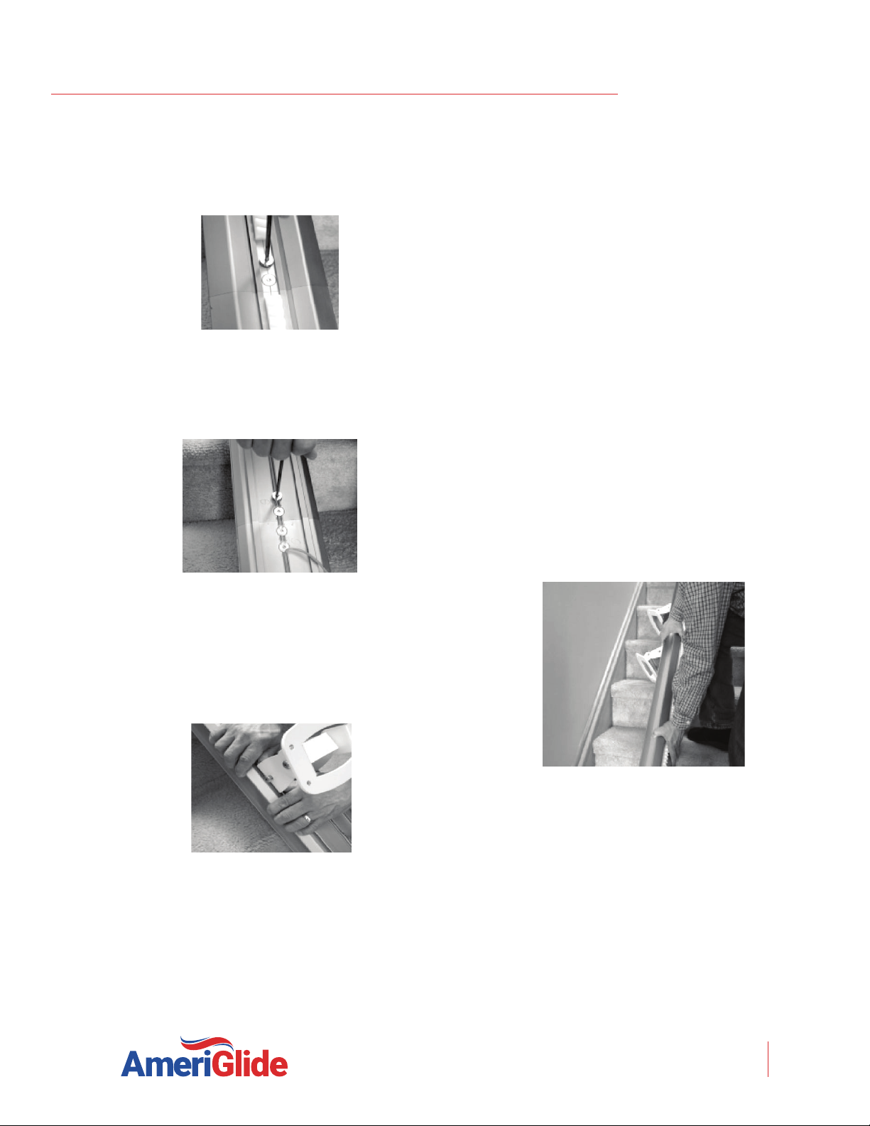
7. Turn rail over and install the remaining two (2)
Allen wrench. See Figure 4-8.
Figure 4-8
8. Install rail brackets with label facing the
staircase side by loosening the screws and
snapping each bracket edge into the slot, or
slide the brackets on from the top of the rail.
See Figure 4-9.
Figure 4-9
NOTE: When installing the track brackets, if the rail is
upside-down, the nut side should be facing the middle of
the staircase, then if the rail is flipped over, the nut side
will face the wall and so will the label.
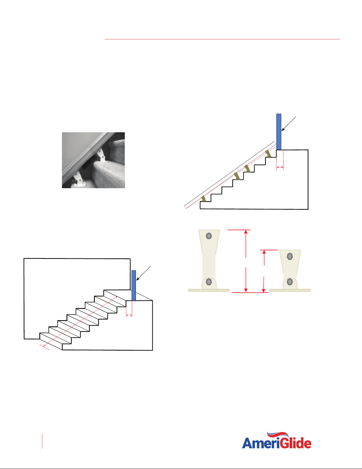
• For double rails, the first rail bracket
should be tightened in place so when
turned over the back of the bracket
touches the riser of the first step from
the bottom landing. The second and third
brackets should be placed and tightened
on the steps on each side of the rail joint,
again so the back of the bracket touches
the riser of the step. The fourth and final
bracket should be placed on the last step
before the top landing, again tightening it
so it touches the front of the riser of the
last step.
• Tighten the first rail bracket in place so
when turned over the back of the bracket
touches the riser of the first step from the
bottom landing. Place the other bracket
on the last step before the top landing,
again tightening it so it touches the riser
of the last step.
9. Turn the rail right side up (gear rack facing up).
See Figure 4-10.
Figure 4-10
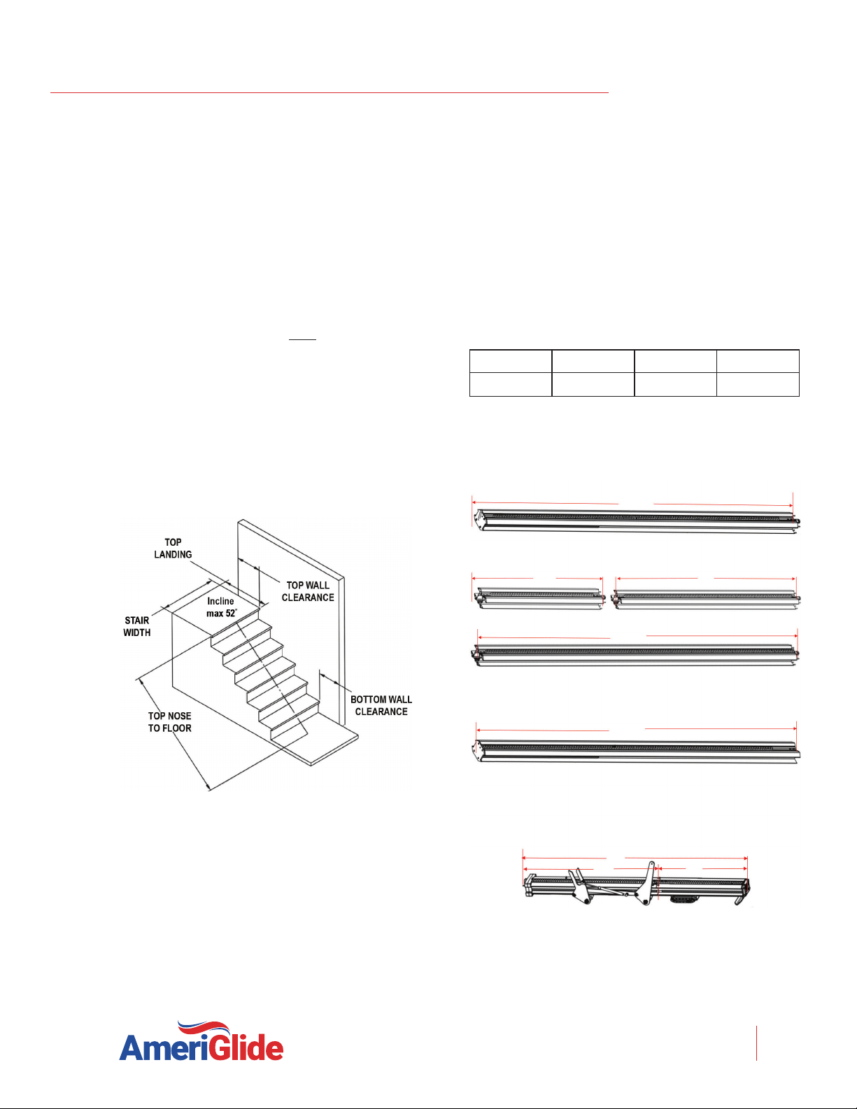
10. Measure any obstruction form the wall (this
may include handrails, molding, light switches,
etc.) and adjust the edge of the brackets and
equal distance from the wall. The minimum
obstruction.
11.
above the stair tread nose to provide

RAVE II STAIR LIFT: Install Manual
04DEC2020 | 630-00078 REV G
10
INSTALLATION
RAVE II STAIR LIFT: SECTION 4
clearance move the rail and bracket forward.
nuts to hold the brackets in position. To
in place, secure the bottom bracket to the
a cordless drill. See Figure 4-11.
Figure 4-11
ZERO INTRUSION
INSTALLATION
1. Measure (A) top landing to (B) bottom landing.
See Figure 4-12.
Figure 4-12
2.
the nose of the top step. See Figure 4-12.
NOTE: The top rail is normally cut unless the length of
travel is short, less than the length of the bottom rail
when the bottom rail will need to be cut.
3.
nose, tall brackets must be used to life the top
of the rail for zero overrun. Multiple tall and/
or short brackets can be ordered.
See Figure 4-13 and 4-14.
Figure 4-13
Figure 4-14
A H
Short BracketTall Bracket
A
B

RAVE II STAIR LIFT: Install Manual
04DEC2020 | 630-00078 REV G
11
INSTALLATION
RAVE II STAIR LIFT: SECTION 4
Be careful not to trap ngers between the rail and
the chassis.
WARNING
!
CHASSIS INSTALLATION
1. Remove chassis from box.
2. Lift the chassis with the manual override hole
(on bottom) facing the downhill side of the
stairs and gently slide the chassis onto the rail
until it makes contact with the plastic rack. Do
not let the chassis free fall down the rail.
See Figure 4-15.
Figure 4-15
3. Remove the zip tie on the power switch and
turn the unit on. The unit will beep once
indicating it is ready for use.
4. Use the installation switch (the black switch
on the top of the chassis) to move the chassis
the chassis to ensure the chassis does not pull
any rack to the top. See Figure 4-16.
Figure 4-16
5. Loosen, but do not remove, the four (4)
seat-leveling bolts (two (2) on each side of the
chassis), and then align them vertically using a
level. Firmly tighten the two (2) bolts on the
side of the chassis facing the wall.
See Figure 4-17.
Two (2) bolts on
either side of the
chassis
Figure 4-17
Do not ride on the chassis or li unl the
installaon is complete.
WARNING
!
switch

RAVE II STAIR LIFT: Install Manual
04DEC2020 | 630-00078 REV G
12
INSTALLATION
RAVE II STAIR LIFT: SECTION 4
FINAL RAIL INSTALLATION
1. Install the remaining plastic rack pieces in the
upper rail. See Figure 4-18.
Figure 4-18
2. Use a hacksaw or chop saw to cut the last
plastic rack piece flush with the rail end. Place
something on the floor to catch debris or mark
and cut the rack outside.
The exposed, cut end of the plastic rack
should be facing the top end of the rail (the
factory-cut side should butt against the lower
rack). See Figure 4-19.
Figure 4-19
3. Slide the top limit cam into one of the
cam slots on either side, and tighten the
wrench. This will be used to set the final upper
limit for the stair lift. See Figure 4-20.
Figure 4-20
4. Remove the charging strips from the rail box.
Connect the charging strip connector to the
power wire that runs through the center of
the rail from the lower charging strips.
Insert the two (2) charging strips into the
keyed slots at the top of the rail (while
standing on the top landing looking down).
The charging strip with the red wire should be
inserted into the left slot with the metal strip
facing out. The charging strip with the black
wire should be inserted into the right slot with
the metal strip pointing out. See Figure 4-21.
Figure 4-21
Bend the red and black wire tabs in toward
the center of the track.
Insert excess cable into the rail, leaving the
pigtail with the Molex connector on the
outside.

RAVE II STAIR LIFT: Install Manual
04DEC2020 | 630-00078 REV G
13
INSTALLATION
RAVE II STAIR LIFT: SECTION 4
5. Install the end plate to the top of the track
with the four (4) self-cutting Torx screws using
the supplied T30 Torx bit. Making sure not to
pinch the wires on the pigtail.
Too much torque applied to these screws may result
in damage. Take your time and apply grease to
threads.
NOTICE
6. Install one of the rack precompression screws
in the threaded hole in the top plate of the
rail, and tighten it as firmly as possible by
See Figure 4-22.
Figure 4-22
7. Plug in the power supply at either end of the
rail, depending on the closest or most
convenient location of a wall power supply.
Minimize wire length and intrusion.
Use care in roung the charger lead. If possible,
secure along or inside wall to avoid the creaon of
a tripping hazard.
WARNING
!
FOOTREST AND SEAT
INSTALLATION
1. Remove the footrest from the box and use the
installation switch to drive the chassis
floor. This will provide a safe area to install
and adjust the footrest. Do not drive the unit
into bottom stop. See Figure 4-23.
Figure 4-23
2.
3. Position the footrest onto the two (2) seat-
leveling bolts on the outside of the chassis by
aligning the large opening at the slot ends of
the footrest. See Figure 4-24.
Figure 4-24
4. Ensure that the footrest is fully engaged.
5. Check that the height of the seat base is
correctly set for the intended user. A seat height
shroud. Consult with the client and use an

RAVE II STAIR LIFT: Install Manual
04DEC2020 | 630-00078 REV G
14
INSTALLATION
RAVE II STAIR LIFT: SECTION 4
If the height of the seat needs to be adjusted,
loosen and remove the four (4) bolts on the
Adjust the seat base up or down relative to
the footrest structure until the holes align,
then replace and securely tighten the four (4)
bolts. See Figure 4-25.
Figure 4-25
6. Connect the footrest cable to the 6-pin
connector on the chassis. See Figure 4-26.
Figure 4-26
7. Position the keyed seat swivel post in the seat
base hole closest to the top of the stairs.
Securely tighten the two (2) bolts on the sides
See Figure 4-27.
Figure 4-27
8. Use the supplied white plastic plugs to secure
the vertical footrest shroud to the main
footrest cover plate.
9. Position the seat directly aligned over the
chassis and place onto the seat swivel post.
Press the swivel lever until the seat is fully
engaged with the swivel post. Check the
swivel lever to test the locking mechanism.
The system will not function if proper
engagement is not achieved. See Figure 4-28.
Figure 4-28
10. Connect the seat cable to the 8-pin connector
on the chassis that is opposite the foot plate
and closest to the wall. See Figure 4-29.
Figure 4-29
If the wrong set of connectors are used, the unit will
work backwards.
NOTICE
When the 6-pin footrest and/or the 8-pin chair cables
are connected to the chassis, the black installation
switch on the chassis is disabled and will not function.
NOTICE

RAVE II STAIR LIFT: Install Manual
04DEC2020 | 630-00078 REV G
15
INSTALLATION
RAVE II STAIR LIFT: SECTION 4
PROCEDURE TO SWITCH
ARMREST CONTROL FROM
RIGHT TO LEFT HAND
1.
2. Flip up armrests and remove the screws on
both armrests.
See Figure 4-30.
Figure 4-30
3. Once the screws are removed, fold the
armrests to the down position and slide the
pad assembles forward until they come off,
then unplug each connector. See Figure 4-31.
Figure 4-31
4. Rotate the pad assembles to the opposite
sides and plug in the connectors on each
armrest. See Figure 4-32.
Figure 4-32
5. Snap both armrests into place and replace the
screws. See Figure 4-33.
Figure 4-33
6.
Off switch located on the top of the chassis
beep. Test the control switch on the armrest.
See Figure 4-34.
Figure 4-34
NOTE: It may be necessary to locate the retractor portion
of the seatbelt on the downward side of the lift to
maintain close distance to the wall.

RAVE II STAIR LIFT: Install Manual
04DEC2020 | 630-00078 REV G
16
INSTALLATION
RAVE II STAIR LIFT: SECTION 4
FOLDING RAIL
INSTALLATION
NOTE: The photos in this section shows a left folding rail,
assembled to be installed on the left side of the stairway.
Contact Ameriglide Technical Support at 866-378-6648
for instructions on how to switch a folding rail from the
left side to the right side.
1. Orient the two(2) rail brackets onto the
folding rail, with the nuts on the same side as
the folding mechanism.
See Figures 4-35 and 4-36.
Figure 4-35
Figure 4-36
2. Expand and snap the two (2) brackets over the
rail, so the top is in the bracket-groove.
See Figures 4-37.
Figure 4-37
3. Partially tighten the two nuts that position
socket preferred), so they won't slide when
you're test-fitting the position. See Figure 4-38.
Figure 4-38
4. Place the rail onto the stairway with the
bottom bracket on the second step, as shown.
NOTE: The bottom feet should approximately rest
on the floor with the rail straight, but they will be
adjusted later. See Figure 4-39.
Figure 4-39

RAVE II STAIR LIFT: Install Manual
04DEC2020 | 630-00078 REV G
17
INSTALLATION
RAVE II STAIR LIFT: SECTION 4
5. Measure to verify that the underside of the
at the second step bracket and at the upper
bracket. If not, reposition the brackets as
needed. This clearance is required for the
stair lift footrest. In some installations, you
standard stair-bracket. Contact Ameriglide to
get tall brackets. See Figures 4-40 and 4-41.
Figure 4-40
Figure 4-41
6. Measure from the side of the rail to the wall.
The minimum clearance that will work with a
from the wall or more. This will leave about
See Figure 4-42.
Figure 4-42
7. Fasten down the near corner of the lower
bracket using a drill that has extensions at
See Figures 4-43 and 4-44.
Figure 4-43
Figure 4-44
8. Measure from the side of the rail at the upper
bracket of the folding rail.
of the bracket.
9. Connect to upper rail, following regular
procedures (see page 8). This procedure
includes plugging the battery charging wire
harness for the folding rail into the charging
harness from the upper rail. The power supply
itself can be plugged into either the top rail
(for the top of the stairs), or to the charge
plug from the folding rail, which comes out
just higher than the folding mechanism for the
bottom of the stairway.
10. Fasten the other screws of both rail brackets
using the power drill and long extension with
See Figure 4-45.

RAVE II STAIR LIFT: Install Manual
04DEC2020 | 630-00078 REV G
18
INSTALLATION
RAVE II STAIR LIFT: SECTION 4
Figure 4-45
11.
open end wrench. Set them so that both rest
on the floor with the rail fully straight. The
foot furthest from the wall should be set a
little taller than the inside one to get it to sit
flat on the floor, since the Rave II rail brackets
intentionally lean the rail toward the wall. See
Figure 4-46.
Figure 4-46
12. Reinstall the two (2) plastic caps on the feet to
cover the threads. See Figure 4-47.
Figure 4-47
13. Carefully move the fork with your hand to
make sure it operates smoothly. Allow it to go
all the way to the floor. Confirm that both feet
sit level on the floor and the hinge-joint is
fully straight. See Figure 4-48.
Figure 4-48
Be careful not to pinch your ngers when moving
the fork.
WARNING
!
14. Follow the normal procedure for installing the
rail brackets and tighten them.
See page 9, step 8.
15. Test ride the unit a couple of times to verify
that the folding rail is operating properly.

RAVE II STAIR LIFT: Install Manual
04DEC2020 | 630-00078 REV G
19
COMPLETION PROCEDURES
RAVE II STAIR LIFT: SECTION 5
SECTION 5
COMPLETION PROCEDURES
REMOTE CONTROL
RE-PROGRAMMING
All call/send controls are factory programmed. In
the event that the remote call/send controls need to
be re-programmed, it is essential to program both
controls in one programming cycle.
1.
position.
2. Disconnect the 6-pin and 8-pin chair wire
harness from the chassis.
3. Press and hold the install switch (located on
the top of the chassis) in either direction.
4.
position. Wait for the circuit board to beep
and then release the install switch.
5. The lift will begin to beep rapidly, advising
that the first remote is ready to be
programmed.
6. Making sure that the remote is pointed at one
of the IR sensors on the chassis, press and
remote. The first remote is now programmed.
7.
on the second remote. The second remote is
now programmed.
8. Upon completion, two beeps will indicate
that both remotes have been successfully
programmed.
9.
position.
10. Connect the 6-pin and 8-pin chair wire
harness to the chassis and then turn the red
11. Test each remote in both the up and down
directions.
TEST ARMREST CONTROL
SWITCH
1. Ensure that the stair lift travels correctly by
operating the armrest control switch while
standing in front of it.
2. Press the switch in the upstairs direction
to move up. The lift will begin to smoothly
accelerate upward. The lift will continue to
move upward as long as the switch is pressed.
3. Release the switch and the lift will come to an
immediate stop.
4. Press the switch in the downstairs direction
to move downward. The lift will begin to
smoothly accelerate downwards.
5. Release the switch and the lift will come to an
immediate stop.
6. Run the lift all the way up and down the rail
to ensure that the top of the seat back has at
obstructions.
Do not ride on the chassis or li unl the
installaon is complete.
WARNING
!

RAVE II STAIR LIFT: Install Manual
04DEC2020 | 630-00078 REV G
20
COMPLETION PROCEDURES
RAVE II STAIR LIFT: SECTION 5
TIGHTEN BRACKETS
Install and fully tighten the rail bracket mounting
screws (four (4) screws per bracket). For hardwood
stairs, a pilot hole should be drilled first. For
plywood or particle board stairs, care must be
taken to prevent stripping.
SET UPPER AND LOWER
TRAVEL LIMITS
1. Test the lower travel limit by operating the lift
downward, keeping the switch pressed. The
its final resting position and stop clear of the
floor.
2. The final stopped position can be adjusted
to accommodate the height of the user by
repositioning the limit cam located in a slot in
the rail.
3.
screw in the limit cam. Adjust the limit cam
up or down and re-tighten the set screws.
Repeat above steps until the lift stops in the
desired position.
4. Repeat the above steps to set the upper limit.
For safety, the footrest should be set at least
level with the upper landing.
5. The optimum position is met when the seat
height above the floor is the same at the top
and bottom of the stairs.
TEST SAFETY STOP
SWITCHES
1. Safety stop switches are located in both the
upward and the downward ends of the chassis
providing protection from obstructions on the
rail.
2. Safety stop is located in the footrest providing
protection from obstructions and tripping
hazards on the stairs.
3. A safety stop switch is part of the swivel
seat mechanism and prevents the lift from
operating when the swivel is in use.
4. Test all safety stop switches by driving the lift
down and touching the downward end of the
chassis, the lower edge of the footrest, and
the underside of the footrest in both its folded
and unfolded positions.
5. In each of the above cases the unit should come to
an immediate halt and should beep intermittently.
6. When the control switch is released, the unit
should not be able to be driven in the direction
that the lift initially engaged the obstacle. Test this
condition.
7. Repeat the above tests while driving the lift in the
opposite direction.
8. If any safety condition does not function properly,
carefully review all installation instructions, reset
9. If any safety stop switch fails to immediately stop
the lift, immediately call Ameriglide for assistance
in diagnosing and repairing the problem. Do not
use the lift.
Table of contents
Other AmeriGlide Stairlift manuals
Popular Stairlift manuals by other brands

Acorn
Acorn 180 user manual

Harmar Mobility
Harmar Mobility PINNACLE SL600HD owner's manual

Savaria
Savaria K2 Plus owner's manual

liftup
liftup FlexStep V2 user manual

Harmar Mobility
Harmar Mobility SL600 HD Owner's manual & warranty information

Harmar Mobility
Harmar Mobility Vantage SL400 Installation and service manual