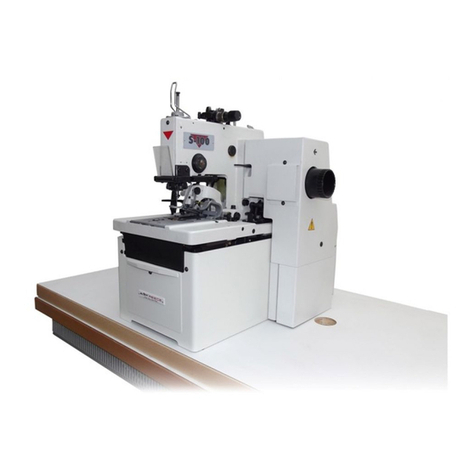
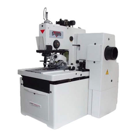
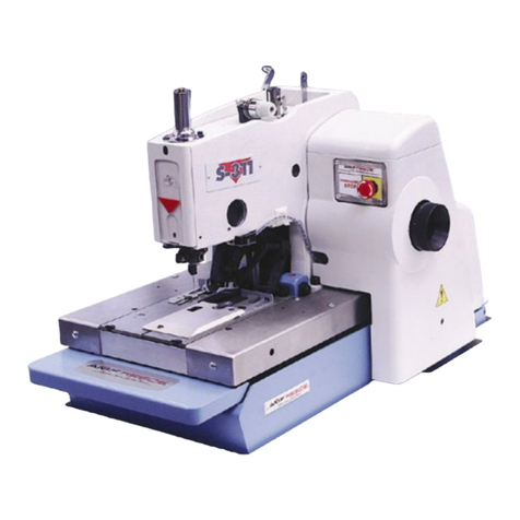
AMF ES-505 Quick start guide

ELECTRONIC EYELET BUTTONHOLE
MACHINE
PARTS AND SERVICE MANUAL
MACHINE SERIAL No:
PART NUMBER 97.1500.0.003
This manual is valid from the machine Serial No.:
MODEL ES-505
R5050058
R5050059
R5050060
R5050061
AMF is trademark of AMF Group, Inc. 12 / 2017


ELECTRONIC EYELET BUTTONHOLE
MACHINE
PARTS AND SERVICE MANUAL
MACHINE SERIAL No:
PART NUMBER 97.1500.0.003
This manual is valid from the machine Serial No.:
MODEL ES-505
R5050058
R5050059
R5050060
R5050061
AMF is trademark of AMF Group, Inc. 12 / 2017


97.1500.0.003 ELECTRONIC EYELET
BUTTONHOLE MACHINE
PARTSAND SERVICE MANUAL
97.1500.0.003 ELECTRONIC EYELET
BUTTONHOLE MACHINE
PARTSAND SERVICE MANUAL
97.1500.0.003 ELECTRONIC EYELET
BUTTONHOLE MACHINE
PARTSAND SERVICE MANUAL
97.1500.0.003 ELECTRONIC EYELET
BUTTONHOLE MACHINE
PARTSAND SERVICE MANUAL
97.1500.0.003 ELECTRONIC EYELET
BUTTONHOLE MACHINE
PARTSAND SERVICE MANUAL
97.1500.0.003 ELECTRONIC EYELET
BUTTONHOLE MACHINE
PARTSAND SERVICE MANUAL
ES-505
ES-505
ES-505
ES-505
ES-505
ES-505


LIMITED WARRANTY ON NEW AMF REECE EQUIPMENT
Warranty provisions:
A ninety (90) day limited service labor warranty to correct defects in installation, workmanship, or mate-
rial without charge for labor. This portion of the warranty applies to machines sold as ”installed” only.
A one (1) year limited material warranty on major component parts to replace materials with defects. Any
new part believed defective must be returned freight prepaid to AMF Reece, Inc. for inspection. If, upon
inspection, the part or material is determined to be defective, AMF Reece, Inc. will replace it without
charge to the customer for parts or material.
Service labor warranty period shall begin on the completed installation date. Material warranty shall be-
gin on the date the equipment is shipped from AMF Reece, Inc.
Exclusions:
Excluded from both service labor warranty and material warranty are: (1) Consumable parts which
would be normally considered replaceable in day-to-day operations. These include parts such as nee-
dles, knives, loopers and spreaders. (2) Normal adjustment and routine maintenance. This is the sole
responsibility of the customer. (3) Cleaning and lubrication of equipment. (4) Parts found to be altered,
broken or damaged due to neglect or improper installation or application. (5) Damage caused by the use
of non-Genuine AMF Reece parts. (6) Shipping or delivery charges.
There is no service labor warranty for machines sold as ”uninstalled”.
Equipment installed without the assistance of a certied technician (either an AMF Reece Employee,
a Certied Contractor, or that of an Authorized Distributor) will have the limited material warranty only.
Only the defective material will be covered. Any charges associated with the use of anAMF Reece
Technician or that of a Distributor to replace the defective part will be the customer’s responsibility.
NO OTHER WARRANTY, EXPRESS OR IMPLIED, AS TO DESCRIPTION, QUALITY, MERCHANTABIL-
ITY, and FITNESS FOR A PARTICULAR PURPOSE, ORANY OTHER MATTER IS GIVEN BY SELLER
OR SELLER’S AGENT IN CONNECTION HEREWITH. UNDER NO CIRCUMSTANCES SHALL SELL-
ER OR SELLER’S AGENT BE LIABLE FOR LOSS OF PROFITS ORANY OTHER DIRECT OR INDI-
RECT COSTS, EXPENSES, LOSSES OR DAMAGESARISING OUT OF DEFECTS IN OR FAILURE
OF THE EQUIPMENT OR ANY PART THEREOF.
WHAT TO DO IF THERE IS A QUESTION REGARDING WARRANTY
If a machine is purchased through an authorized AMF Reece, Inc. distributor, warranty questions should
be rst directed to that distributor. However, the satisfaction and goodwill of our customers are of pri-
mary concern to AMF Reece, Inc. In the event that a warranty matter is not handled to your satisfaction,
please contact AMF Reece oce:
Prostejov, Czech Republic
Phone: (+420) 582-309-275
Fax: (+420) 582-360-608

e-mail: [email protected]


Warranty Registration Card
(Please Fax or Mail immediately after installation)
Note: All Warranty Claims Void, unless Registration Card on le at AMF Reece HQ
Machine model number:
(S101, S100, S104, S105, S311, Decostitch, S4000, EBS Mark II, etc)
Manufacturer‘s serial or production number:
Installation Site Information:
Customer‘s Name:
Customer‘s Mailing Address:
Customer‘s Telephone Number:
Supervising Mechanic‘s or Technician‘s Name:
Signature of Supervising Technician:
AMF Reece Technician‘s Name:
AMF Reece Technician‘s Signature:
Type of garment produced at this location?
Average Daily Production Expected from this machine?
(number of buttonholes, jackets sewn, pants produced, buttons sewn, etc)
Any special requirements required at this location?
What other AMF Reece Machines are at this location?
How can we serve you better?


Released: 12/2017
E-mail: [email protected]; webside: amfreece.com
Phone: +420 582 309 146; Fax: +420 582 360 606
A-INTRODUCTION
1. BASIC INFORMATION............................................................................................................................1-1
1.1. Basic types of trimming machanism.......................................................................................................1-1
1.2. Trimming mechanism oered with machine types .................................................................................1-1
2. SAFETY INSTRUCTIONS......................................................................................................................1-2
2.1. Safety symbols and their meanings ......................................................................................................1-2
2.2. General safety instructions.....................................................................................................................1-2
2.3. Delivery safety instructions ....................................................................................................................1-3
2.4. Installation and maintanace safety instruction .......................................................................................1-3
2.5. Daily operation safety instructions for operator......................................................................................1-3
2.6. Safety and instruction labels on the machine.........................................................................................1-4
3. COLOUR MARKS ON THE MACHINE..................................................................................................1-6
4. GENERAL MACHINE PARTS DESCRIPTION......................................................................................1-7
4.1. Basic model...........................................................................................................................................1-7
4.2. Ultraex model .......................................................................................................................................1-8
4.2.1. Models of machines with ultraex: ......................................................................................................1-8
4.2.2. Use of the machine: ............................................................................................................................1-9
4.3. Indexer model ........................................................................................................................................1-10
4.3.1. Models of es-505 indexer machine .....................................................................................................1-10
4.3.2. Use on the machine ............................................................................................................................1-10
5. TECHNICAL CONDITIONS....................................................................................................................1-11
5.1. BASIC MODEL......................................................................................................................................1-11
5.2. ULTRAFLEX MODEL............................................................................................................................1-12
5.3. INDEXER MODEL................................................................................................................................1-13
6. TERMINOLOGY USED TO DESCRIBE BUTTONHOLE PARTS ........................................................1-14
7. BUTTONHOLLE TYPES AND CUTTING OPTIONS ............................................................................1-14
7.1. Standard models....................................................................................................................................1-14
7.2. Ultraex model .......................................................................................................................................1-15
8. SPECIALACCESSORIES......................................................................................................................1-16
B-MACHINE INSTALATION
1. CONSIGNMENT CONTENT...................................................................................................................1-17
2. STAND ADJUSTMENT............................................................................................................................1-17
3. PLACING MACHINE...............................................................................................................................1-18
4. THREAD STAND INSTALLATION..........................................................................................................1-18
5. CHECKING OIL TANK.............................................................................................................................1-19
6. CONNECTING MACHINE WITH ELECTRICITYAND AIR DISTRIBUTION......................................1-20
C-PROPER USAGE
1. BEFORE STARTING SEWING...............................................................................................................1-21
1.1. Adjusting needle.....................................................................................................................................1-21
1.2. Threading...............................................................................................................................................1-21
1.3. Threading upper thread..........................................................................................................................1-22
1.4. Threading bottom thread........................................................................................................................1-23
1.5. Gimp draw o.........................................................................................................................................1-24
2. LUBRICATION.........................................................................................................................................1-25
2.1. Filling up oil ..........................................................................................................................................1-25
2.2. Lubricating important parts.....................................................................................................................1-26
3. PUTTING MACHINE INTO HOME POSITION FOR SEWING ...........................................................1-27
4. LOADING FABRIC...................................................................................................................................1-28
5. SEWING BUTTONHOLE........................................................................................................................1-29
6. BROKEN THREAD..................................................................................................................................1-30
D-MACHINE CONTROLS
1. TOUCH SCREEN ....................................................................................................................................1-31
1.1. Display menu..........................................................................................................................................1-31
1.2. Buttons and icons commonly used ........................................................................................................1-34
1.3. Before initial programming .....................................................................................................................1-35
TABLE OF CONTENTS
ES-505

Released: 12/2017
E-mail: [email protected]; webside: amfreece.com
Phone: +420 582 309 146; Fax: +420 582 360 606
2. PROGRAMMING.....................................................................................................................................1-36
2.1. Buttonhole program options...................................................................................................................1-36
2.2. Program name options...........................................................................................................................1-37
2.3. Setting buttonhole parameters...............................................................................................................1-38
2.3.1. Setting eye parameters.......................................................................................................................1-38
2.3.2. Setting parameters round buttonhole..................................................................................................1-39
2.3.3. Setting parameters of rst and secod raw of stitches..........................................................................1-40
2.3.4. Buttonhole ending setup......................................................................................................................1-41
2.3.4.1. Setting buttonhole open end ............................................................................................................1-41
2.3.4.2. Setting buttonhole y bar .................................................................................................................1-41
2.3.4.3. Setting buttonhole cross bar ............................................................................................................1-42
2.3.4.4. Setting round end of buttonhole with sewing starting in eye............................................................1-42
2.3.4.5. Setting round end of buttonhole with sewing starting in eye ...........................................................1-43
2.4. Setting buttonhole cutting ......................................................................................................................1-44
2.5. Setting round buttonhole cutting ............................................................................................................1-45
2.6. Ultraex ..................................................................................................................................................1-46
2.6.1. Cutting the whole buttonhole...............................................................................................................1-46
2.6.2. Cutting the straight part of the buttonhole...........................................................................................1-47
2.6.3. Cutting the eye or part of buttonhole with the eye ..............................................................................1-47
2.7. Indexer model ........................................................................................................................................1-48
2.8. Setting electronic thread tension............................................................................................................1-49
2.9. Setting up buttonhole sewing speed ......................................................................................................1-50
2.10. Setting up round end buttonhole sewing speed (rde)...........................................................................1-50
3. CYCLE MODE .........................................................................................................................................1-51
3.1. Selection of program number in standard cycle mode...........................................................................1-51
3.2. Buttonhole program selection in cycle mode .........................................................................................1-52
3.3. Setting cycle mode with active optical sensor........................................................................................1-53
4. INDEXER MODEL...................................................................................................................................1-55
4.1. Indexer main screen description ............................................................................................................1-55
4.2. Setting indexer cycle..............................................................................................................................1-56
4.3. Buttonhole parameters changing ...........................................................................................................1-57
5. ADITIONAL FUNCTIONS ......................................................................................................................1-58
5.1. Productivity (cycle counter)....................................................................................................................1-58
5.1.1. Setting dayily cycle counter.................................................................................................................1-58
5.2. Error messages......................................................................................................................................1-59
5.3. Discharged battery.................................................................................................................................1-59
E-STANDARD MACHINE ADJUSTMENT
1. STANDARD BUTTONHOLE SHAPES SET BY MANUFACTURER....................................................1-60
2. SERVICE MENU DISPLAY.....................................................................................................................1-61
2.1. Service menu display guide ...................................................................................................................1-61
2.2. Password login.......................................................................................................................................1-63
2.2.1. Passwords and protecting levels.........................................................................................................1-63
2.3. Informative screen..................................................................................................................................1-63
2.4. Buttonhole program copying ..................................................................................................................1-64
2.5. Machine setting......................................................................................................................................1-65
2.6. Selection of model and machine accessories........................................................................................1-66
2.6.1. Selection of standard model and machine accessories......................................................................1-66
2.6.2. Ultraex model ....................................................................................................................................1-68
2.6.3. Selection of optical senzor for ultraex model.....................................................................................1-69
2.7. Input testing............................................................................................................................................1-70
2.8. Output testing.........................................................................................................................................1-70
2.9. Motor testing ..........................................................................................................................................1-71
2.10. Electronic thread tension test...............................................................................................................1-71
3. REPEATED FABRIC CUT MODE ..........................................................................................................1-72
4. SETTING UP PLC ACCORDING TO MACHINE TYPE........................................................................1-72
5. SETTING UP SEWING DRIVE SENSOR RINGS.................................................................................1-73
TABLE OF CONTENTS
ES-505

Released: 12/2017
E-mail: [email protected]; webside: amfreece.com
Phone: +420 582 309 146; Fax: +420 582 360 606
5.1. Setting up sensor screen bq1.................................................................................................................1-73
5.2. Setting up sensor screen bq8 ................................................................................................................1-73
6. SETTING BED PLATE ............................................................................................................................1-74
7. SETTING UP TURNING MECHANISM .................................................................................................1-75
8. CHECKING SEWING MECHANISM HEIGHT.......................................................................................1-76
9. SETTING UP MECHANISM CLAMPING FABRIC................................................................................1-77
10. VARIOUS SPREADING OF WORKPIECE ........................................................................................1-78
11. CUTTING MECHANISM SET UP.........................................................................................................1-79
11.1. Checking cutting mechanism setup......................................................................................................1-79
11.2. Knife and cutting steel set up – standard: ............................................................................................1-81
11.3. Knife and cutting steel set up – ultraex:..............................................................................................1-82
11.4. Pressure and cutting sensor adjustment: .............................................................................................1-83
12. KNIFE AND CUTTING STEEL EXCHANGE ......................................................................................1-84
12.1. Cutting with xed cutting steel..............................................................................................................1-84
12.2. Modication of cutting steels surface ..................................................................................................1-85
12.3. Cutting with sliding cutting steel (ultraex) ..........................................................................................1-85
13. STANDARD SEWING CAM SETTING.................................................................................................1-86
14. ADJUSTING THE NEEDLE AND LOOPER TIMING..........................................................................1-87
15. ADJUSTING THE LOOPER STROKE.................................................................................................1-88
16. ADJUSTING THE HEIGHT OF THE NEEDLE BAR ...........................................................................1-89
17. ADJUSTMENT OF DISTANCE BETWEEN NEEDLE AND LOOPERS.............................................1-90
18. LOOPERS ADJUSTMENT....................................................................................................................1-91
19. STITCH BITE MECHANISM SET UP .................................................................................................1-92
20. UPPER THREAD TRIMMING MECHANISM - AF, LTT.......................................................................1-93
21. BOTTOM THREADAND GIMP TRIMMING - LTT...............................................................................1-94
22. LTT KNIFE REPLACEMENT ................................................................................................................1-95
22.1. Replacing moving knife:.......................................................................................................................1-95
22.2. Replacing xed knife: ...........................................................................................................................1-95
23. KNIVES ADJUSTMENT - LTT...............................................................................................................1-96
24. BOTTOM THREAD HOLDER ADJUSTMENT - LTT...........................................................................1-97
24.1. Bottom thread holder opener:...............................................................................................................1-97
24.2. Ltt bottom thread guide: .......................................................................................................................1-97
25. UPPER THREAD NIPPER MECHANISM............................................................................................1-98
26. UPPER TRIMMING AND LOWER INTERCEPTION - CT..................................................................1-99
27. CT KNIFE REPLACEMENT AND ADJUSTMENT ..............................................................................1-100
27.1. Knife replacement and adjustment ......................................................................................................1-100
27.2. Cutting pressure set up........................................................................................................................1-100
28. CLAMPING FEET..................................................................................................................................1-101
28.1. Sheers adjustment ...............................................................................................................................1-101
28.2. Bottom thread trimming and gimp trimming mechanism......................................................................1-101
29. SPREADERS AND THREAD TENSIONER ADJUSTMENT ..............................................................1-102
29.1. Upper thread .......................................................................................................................................1-102
29.2. Bottom thread.......................................................................................................................................1-103
29.3. Gimp.....................................................................................................................................................1-104
F-STANDARD MACHINE ADJUSTMENT INDEXER MODEL
1. SETTING UP THE HEIGHT OF CLAMPING FEET..............................................................................1-105
2. SETTING UP MINIMAL PLAY BETWEEN INDEXER FEETAND CLAMPING MAT..........................1-106
3. SETTING UP THE DISTANCE BETWEEN CLAMPING FEET............................................................1-107
G-MACHINE MAINTENANCE
1. MACHINE CLEANING AND MAINTENANCE.......................................................................................1-109
1.1. Daily cleaning and checking...................................................................................................................1-109
1.1.1. Sewing mechanism cleaning...............................................................................................................1-109
1.1.2. Filter unit cleaning and maintenance...................................................................................................1-110
1.1.3. Needle check.......................................................................................................................................1-110
1.2. Cleaning and checking as needed.........................................................................................................1-111
TABLE OF CONTENTS
ES-505

Released: 12/2017
E-mail: [email protected]; webside: amfreece.com
Phone: +420 582 309 146; Fax: +420 582 360 606
1.2.1. Control box..........................................................................................................................................1-111
1.2.2. Draining lubrication oil out...................................................................................................................1-111
1.2.3. Eye safety cover..................................................................................................................................1-111
1.2.4. Lubrication...........................................................................................................................................1-111
1.2.5. Battery replacement............................................................................................................................1-112
2. MAINTENANCE LIST..............................................................................................................................1-113
3. MACHINE DISPOSAL.............................................................................................................................1-113
H-DOCUMENTATION
1. PNEUMATIC DIAGRAM..............................................................................................................................1-114
2. ELECTRICAL DIAGRAM ............................................................................................................................1-115
TABLE OF CONTENTS
ES-505

ES-505
1-1
A - INTRODUCTION
Released: 01/2018
Phone: +420 582 309 146; Fax: +420 582 360 606
1. BASIC INFORMATION
Thank you for buying our electronic buttonhole machine ES 505. Before putting the machine into initial operation,
please read carefully this service manual. The rst part covers installation, adjustment, operation and service of the
machine. The second part is to provide information to help with ordering spare parts for this machine.
ES-505 is electronic apparel buttonhole machine. It is used for sewing all types of buttonholes on dierent kinds of
fabrics and with options of cut before (CB) or cut after (CA) sewing. The machine can sew chain stitch with double
or single thread and optionally with gimp.
The machine is equipped with patented mechanisms to lower noise and vibration during high production. Basic
sewing parameters are set on the touch display using simple and understandable graphics. The ES 505 machine was
designed and produced in such way to be reliable safe and user friendly.
Machine models of ES 505 have dierent types of trimming mechanism. For the models see the table below.
Basic types of trimming machanism
Trimming mechanism
oered with machine
types
AF CT LTT
AF CT 14 - 26 LTT
AF + I CT 22 - 35 LTT RDE
AF + RDE CT 14 - 26 + 1 ULTRAFLEX
ULTRAFLEX CT + RDE
Abbreviations used in the manual
CA Cutting buttonhole after sewing
CB Cutting buttonhole before sewing
AF Automatic top thread trimming
CT Automatic trimming of all threads – short tail
LTT Automatic trimming of all threads – long tail
RDE Round eylet
Ultraex Automatic cutting lenght system of buttonhole
IIndexer

ES-505
1-2 Released: 01/2018
Phone: +420 582 309 146; Fax: +420 582 360 606
B - MACHINE INSTALATION
2. SAFETY INSTRUCTIONS
Do not put the machine into operation until you have read all manuals supplied with the machine and you
understood each function and operation!
WerecommendAMFReeceservicemen tobepresent at themachineinstallation andinitialtraining of yourmechanics
and operators.
The most eective method of ensuring safety of operators working on the machine is a strict company safety program
including instructions for safety operation. Operators and maintenance should use goggles.
2.1. SAFETY SYMBOLS AND THEIR MEANINGS
Electronic safety device protects an operator as well as the machine. It respects valid safety and hygiene standards
forregulartechnological machine usage.This safety device includes theplugfork,operational switch (safety breaker),
air pressure switch and covers ensuring safety work on the machine only if they are tted correctly.
Mentioned measures cannot cover all safety aspects and therefore it is necessary for the operator to read and
understand this manual before using the machine. These will eliminate errors during machine installation and
machine operation too.
This manual includes four categories of safety instructions:
DANGER! Overlooking instructions may endanger operator’s life.
WARNING! Overlooking instructions may cause severe injury of the operator or damage the machine.
CAUTION! Overlooking instructions may damage the machine or cause injury of the operator.
NOTE! Breaching procedures may cause functional problems with the machine.
2.2. GENERAL SAFETY INSTRUCTIONS
• Before plugging the machine into electricity, make sure that all covers are tted. Do not put the machine into
electricity if any of the covers is removed.
• Remember where the STOP button is placed, so that you can use it at any time.
• Check that electric cables are not damaged. Bare cable could cause an injury. Repair damaged covers or replace
them with new ones.
• Do not touch rotating and moving parts at any circumstances.
• Do not put your ngers into the sewing needle area at any circumstances.
• Before changing the needle, switch o the main switch.
• Always unplug the machine from the electricity before machine maintenance and cleaning.
• If you are not going to work on the machine, disconnect the power supply with the main switch.
• Do not modify the machine in any way that could endanger its safety.
• Keep in mind, that improper handling or wrong maintenance can make every part of the machine dangerous.
It is very important that whoever works with the machine – operate it or do maintenance – is acquainted with
information in this brochure and parts catalogue.
• Do not miss out doing regular maintenance in accordance with the operational manual.
• If the electricity power supply breaks down, switch the machine with the main switch.
• Do not remove, damage, modify or paint safety labels, but keep them clean. In case they are not legible or not in
place, order a new label and place it onto the original spot.
• If you have long hair, make them in such way, that it cannot be caught and trapped by the driving mechanism.
• Buttons (hooks) on the sleeves always keep on, to avoid the danger of wrapping loose clothing to the drive
mechanism.
• Do not work on the machine impaired or intoxicated.

ES-505
1-3
A - INTRODUCTION
Released: 01/2018
Phone: +420 582 309 146; Fax: +420 582 360 606
2.3. DELIVERY SAFETY INSTRUCTIONS
When unwrapping the machine, follow the marks and symbols on the box and wrapping.
Visible damages of the consignment caused during shipment must be reported to the freight forwarder
immediately.Checkthecontentoftheconsignmentwiththeorderandinformthemanufactureronanydiscrepancies.
Later claims will not be taken into consideration!
2.4. INSTALLATION AND MAINTANACE SAFETY INSTRUCTION
The machine is tted with a lter to suppress noise according to the standars (EMC - ČSN 50081-1 and
50081-2). In case there is a circuit breaker connected in the power system, it must be a type for devices with stray
current and with high resistance to surge current in the operational conductor (ie. “S” type).
If there is a need to remove any of the safety covers, switch o the main switch, and possibly unplug the
machine from the electricity.
It is strictly forbidden to connect any connector while the machine is switched on and under voltage! Electrical
parts and motors may get damaged.
Makesurethatelectricitysupplyanditsdimensioningandprotectionprovidestableelectricitysupplynecessary
for reliable machine performance.
2.5. DAILY OPERATION SAFETY INSTRUCTIONS FOR OPERATOR
Do not connect the machine onto power supply, if any of the safety covers is removed.
Check there are no bare electrical cables that could cause injury.
If you are not sure about proper operational procedure, it is necessary to call a mechanic.
The user has to ensure the lightning of minimum 750 Luxs.

ES-505
1-4 Released: 01/2018
Phone: +420 582 309 146; Fax: +420 582 360 606
A - INTRODUCTION
2.6. SAFETY AND INSTRUCTION LABELS ON THE MACHINE

ES-505
1-5
A - INTRODUCTION
Released: 01/2018
Phone: +420 582 309 146; Fax: +420 582 360 606

ES-505
1-6 Released: 01/2018
Phone: +420 582 309 146; Fax: +420 582 360 606
A - INTRODUCTION
3. COLOUR MARKS ON THE MACHINE
SCREW
CONNECTIONS
YELLOW MARKS
Loosening and dismantling this joint is signicant hit to the
adjustment of the mechanism, which was done at the manufacturer
during assembly and nal sew o. After such interference into the
mechanism, new adjustmet of the mechanism and full inspection
of the machine adjustment is necessary.
BLUE MARKS Screws and nuts are secured with LOCTITE glue against
loosening.
LUBRICATION
POINTS RED MARKS CAUTION! In order to keep the machine in operation
reliable and long life, follow and keep the lubrication instructions.
For details see chapter C2.
Table of contents
Other AMF Sewing Machine manuals

AMF
AMF S 4000 TKF Quick start guide

AMF
AMF DECO 2000 User manual

AMF
AMF REECE S-311 Quick start guide

AMF
AMF S-4000 Quick start guide

AMF
AMF Reece S-101 User manual

AMF
AMF REECE S-311 Quick start guide

AMF
AMF S-4000 Quick start guide

AMF
AMF SERIES S104-130 Quick start guide

AMF
AMF S-4000 BH Omron Quick start guide

AMF
AMF S-4000 Quick start guide