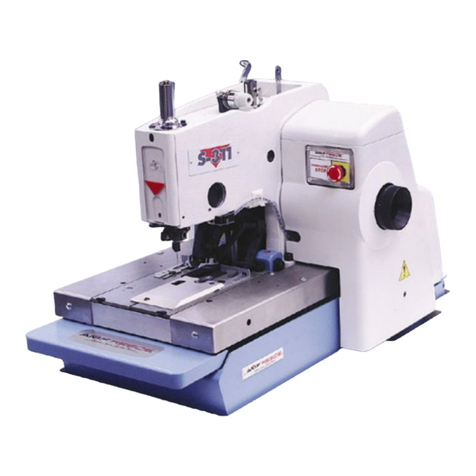
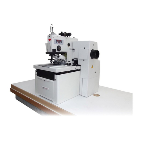
AMF REECE S-105 Quick start guide

MODEL S-105
MECHANICAL EYELET BUTTONHOLE
MACHINE
PARTSAND SERVICE MANUAL
MACHINE SERIAL No.
PARTNUMBER 97. 1100.0.000
AMF is trademark of AMF Group, Inc.
This manual is valid fromthe machine serial No.:K1500011
12/2007


MODEL S-105
MECHANICAL EYELET BUTTONHOLE
MACHINE
PARTSAND SERVICE MANUAL
MACHINE SERIAL No.
PARTNUMBER 97. 1100.0.000
AMF is trademark of AMF Group, Inc.
This manual is valid fromthe machine serial No.:K150001
12/2007


S-105
97.1930.0.001 MECHANICAL EYELET BUTTONHOLEMACHINE
PARTSANDSERVICEMANUAL
S-105
S-105
S-105
S-105
S-105
97.1930.0.001 MECHANICAL EYELET BUTTONHOLEMACHINE
PARTSANDSERVICEMANUAL
97.1930.0.001 MECHANICAL EYELET BUTTONHOLEMACHINE
PARTSANDSERVICEMANUAL
97.1930.0.001 MECHANICAL EYELET BUTTONHOLEMACHINE
PARTSANDSERVICEMANUAL
97.1930.0.001 MECHANICAL EYELET BUTTONHOLEMACHINE
PARTSANDSERVICEMANUAL
97.1930.0.001 MECHANICAL EYELET BUTTONHOLEMACHINE
PARTSANDSERVICEMANUAL


LIMITEDWARRANTYON NEWAMFREECE EQUIPMENT
Warrantyprovisions:
A ninety (90) day limited service labor warranty to correct defects in installation, workmanship, or material without charge for
labor. This portion of the warranty applies to machines sold as ”installed” only.
A one (1) year limited material warranty on major component parts to replace materials with defects. Any new part believed
defective must be returned freight prepaid to AMF Reece, Inc. for inspection. If, upon inspection, the part or material is deter-
mined to be defective, AMF Reece, Inc. will replace it without charge to the customer for parts or material.
Service labor warranty period shall begin on the completed installation date. Material warranty shall begin on the date the
equipment is shipped from AMF Reece, Inc.
Exclusions:
Excludedfromboth servicelabor warranty andmaterial warrantyare: (1)Consumable partswhich would benormally considered
replaceable in day-to-day operations. These include parts such as needles, knives, loopers and spreaders. (2) Normal adjustment
and routine maintenance. This is the sole responsibility of the customer. (3) Cleaning and lubrication of equipment. (4) Parts
found to be altered, broken or damaged due to neglect or improper installation or application. (5) Damage caused by the use of
non-Genuine AMF Reece parts. (6) Shipping or delivery charges.
There is no service labor warranty for machines sold as ”uninstalled”.
Equipment installed without the assistance of a certified technician (either anAMF Reece Employee, a Certified Contractor, or
that of anAuthorized Distributor) will have the limited material warranty only. Only the defective material will be covered. Any
charges associated with the use of an AMF Reece Technician or that of a Distributor to replace the defective part will be the
customer’s responsibility.
NOOTHERWARRANTY,EXPRESSORIMPLIED,ASTODESCRIPTION,QUALITY,MERCHANTABILITY,andFITNESSFOR
APARTICULARPURPOSE,ORANYOTHERMATTERISGIVENBYSELLERORSELLER’SAGENTINCONNECTIONHERE-
WITH. UNDERNOCIRCUMSTANCESSHALLSELLERORSELLER’SAGENTBELIABLEFORLOSSOFPROFITSORANY
OTHERDIRECTORINDIRECTCOSTS,EXPENSES,LOSSESORDAMAGESARISINGOUTOFDEFECTSINORFAILUREOF
THEEQUIPMENTORANYPARTTHEREOF.
WHATTODOIFTHEREISAQUESTIONREGARDINGWARRANTY
If a machine is purchased through an authorizedAMF Reece, Inc. distributor, warranty questions should be first directed to that
distributor. However, the satisfaction and goodwill of our customers are of primary concern toAMF Reece, Inc. In the event that
a warranty matter is not handled to your satisfaction, please contact the appropriate AMF Reece office:
(+420) 582-309-275
(+420) 582-360-608
servi[email protected]
(+90) 212-465-0707
(+90) 212-465-0711
amfreeceturkey@superonline.com
(+852) 2787-2273
(+852) 2787-5642
amfreece@netvigator.com
Europe/Africa/Americas
Prostejov, Czech Republic
Phone:
Fax:
e-mail:
Southwest Asia
Istanbul, Turkey
Phone:
Fax:
e-mail:
Southeast Asia
Kowloon, Hong Kong
Phone:
Fax:
e-mail:
Warranty Registration Card
(Please Fax or Mail immediately after installation)
Note:AllWarrantyClaimsVoid,unless Registration Cardon file atAMF ReeceHQ
Machinemodelnumber:
(S101, S100, S104, S311, Decostitch, S4000 BH, etc)
Manufacturer‘sserialorproduction number:
Installation Site Information:
Customer‘sName:
Customer‘sMailing Address:
Customer‘sTelephoneNumber:
SupervisingMechanic‘sorTechnician‘sName:
SignatureofSupervisingTechnician:
AMFReeceTechnician‘sName:
AMFReeceTechnician‘sSignature:
Typeof garmentproducedatthislocation?
AverageDailyProductionExpectedfromthismachine?
(number of buttonholes, jackets sewn, pants produced, buttons sewn, etc)
Anyspecialrequirementsrequiredatthislocation?
WhatotherAMFReece Machinesareatthislocation?
Howcanweserveyoubetter?
Tovární 582, 796 25 Prostějov, Czech Republic
Fax: +420 582 360 606, e-mail: service@amfreece.cz, website: www.amfreece.com

S-105
Revised 04/2008
E-mail: service@amfreece.cz; parts@amfreece.cz; website: www.amfreece.com
Phones: +420 582 309 146 (Service), +420 582 309 286 (Spare Parts); Fax: +420 582 360 606 1-i
A - INTRODUCTION
1. General information .......................................................................................................................... 1-1
2. Terminology of machine parts and safety labels on the machine ....................................................... 1-2
3. Technical condition ........................................................................................................................... 1-4
4. Terminology of buttonhole parts ....................................................................................................... 1-5
5. Coloured markings ............................................................................................................................ 1-6
6. Safety instructions for operators and servicemen ............................................................................... 1-6
7. Special equipment ............................................................................................................................. 1-8
B - MACHINE INSTALATION
1. Contents of consignment ................................................................................................................... 1-9
2. Table instalation ................................................................................................................................ 1-9
3. Thread stand instalation ................................................................................................................... 1-10
4. Connecting machine with distribution of electricity .......................................................................... 1-11
5. Adjustment of drive belt tension to sew .......................................................................................... 1-12
6. Adjustment of left drive belt ........................................................................................................... 1-13
C - CORRECT USAGE
1. Sewing of buttonhole ...................................................................................................................... 1-14
2. Needle exchange ............................................................................................................................ 1-15
3. Threading of machine ..................................................................................................................... 1-15
4. Principles of sewing ........................................................................................................................ 1-19
5. Machine description and its functions .............................................................................................. 1-20
6. Changing seaming width ................................................................................................................. 1-20
7. Stitch density adjustment ................................................................................................................. 1-21
8. Stitching lenght and flybar adjustment ............................................................................................ 1-22
9. Changing the position of stitch rows - gaps for cut ......................................................................... 1-23
10. Setting the spread of the clapm feet ................................................................................................. 1-23
D - MACHINEADJUSTMENT
1. Table adjustment ............................................................................................................................. 1-25
2. Stopping mechanism ....................................................................................................................... 1-26
3. Stopping stroke adjustment ............................................................................................................. 1-28
4. Brake adjustment ............................................................................................................................ 1-29
5. Needle bar and race alignment ........................................................................................................ 1-30
6. Buttonhole shape adjustment .......................................................................................................... 1-31
7. Needle bar height ............................................................................................................................ 1-32
8. Loopers adjustment ......................................................................................................................... 1-33
9. Spreaders adjustment ...................................................................................................................... 1-35
10. Upper thread trimming .................................................................................................................... 1-36
11. Upper thread tension ....................................................................................................................... 1-37
12. Sewing switch lewer ....................................................................................................................... 1-38
13. Cutting mechanism adjustment ........................................................................................................ 1-39
14. Adjustment of clamping mechanism ............................................................................................... 1-41
E - MAINTENANCE
1. Machine cleansing and maintenance ............................................................................................... 1-43
2. Summary of maintenance ................................................................................................................ 1-44
3. Machine lubrication ......................................................................................................................... 1-45
4. Disposal provisions .......................................................................................................................... 1-47
TABLE OF CONTENTS

Revised 12/2006
E-mail: service@amfreece.cz; parts@amfreece.cz; website: www.amfreece.com
Phones: +420 582 309 146 (Service), +420 582 309 286 (Spare Parts); Fax: +420 582 360 606
S-105
1-ii
TABLE OF CONTENTS

Revised 12/2007
E-mail: service@amfreece.cz; parts@amfreece.cz; website: www.amfreece.com
Phones: +420 582 309 146 (Service), +420 582 309 286 (Spare Parts); Fax: +420 582 360 606
S-105
1-1
A - INTRODUCTION
1. GENERAL INFORMATION
S-105 sewing machine is intended for sewing buttonholes on outwear. It has been designed and
manufactured to be reliable and easy to operate. Special attention is paid to ensure ease and effective
safety for machine operators and servicemen.
Safety mechanisms protect both, operators and the machine, and respect valid safety and hygiene provisions
for usual technological usage of the machine. Those safety mechanisms contain electrical plug, operation
switch (circuit breaker) and covers ensuring safety operation on the machines; only if they are fitted onto
the machine correctly.
There are information labels on the machine to point out additional danger. Do not remove or damage
those labels. In case of damage, order a new one. Mentioned warnings cannot cover all safety aspects and
therefore it is very important for an operator to read this manual carefully and understand it well before he
starts operating the machine. It will also eliminate errors during machine installation and its operation. Do
not put the machine into operation unless you have read entire manuals supplied with the machine and
have understood each function and procedure.
There are four categories of safety instructions in this manual:
DANGER! Ignoring instructions may endanger operator’s life.
CAUTION! Ignoring instructions may cause a serious injury of the operator or damage the machine.
WARNING! Ignoring instructions may cause damage on the machine or injury of the operator.
NOTICE! Breaking procedures may cause functional problems of the machine.
We recommend that servicemen from AMF Reece supervise the installation of the machines and initial
training of your mechanics and operators.
The most effective method ensuring safety of operators working on the machine is a strict safety program
including instructions for safety operation. Operators and servicemen should wear safety glasses.

Revised 12/2007
E-mail: service@amfreece.cz; parts@amfreece.cz; website: www.amfreece.com
Phones: +420 582 309 146 (Service), +420 582 309 286 (Spare Parts); Fax: +420 582 360 606
S-105
1-2
2. TERMINOLOGY OF MACHINE PARTS AND SAFETY LABELS ON THE MACHINE
ÊCaution when removing cover,
shock hazard
ËAccident hazard
ÌCaution when removing cover, chance of injury
ÍGrounding
ÎSwitch
ÏNeedle bar cover
A - INTRODUCTION
Ê
Ë
Ì
Í
Ì
Ë
Î
Ð
Ñ
Ò
Ó

Revised 12/2007
E-mail: service@amfreece.cz; parts@amfreece.cz; website: www.amfreece.com
Phones: +420 582 309 146 (Service), +420 582 309 286 (Spare Parts); Fax: +420 582 360 606
S-105
1-3
ÐRear removable cover
ÑThread stand
ÒTable
ÓStand
A - INTRODUCTION
Foot pedal
Driver belt cover
Motor
Hand screw
Ð
Ï

Revised 12/2007
E-mail: service@amfreece.cz; parts@amfreece.cz; website: www.amfreece.com
Phones: +420 582 309 146 (Service), +420 582 309 286 (Spare Parts); Fax: +420 582 360 606
S-105
1-4
A - INTRODUCTION
NOTICE: If you use threads 100 thick or less, the manufacturer recommend using the left looper order
number 11.4005.0.005
3. TECHNICAL CONDITIONS
S-105 Mechanical eyelet buttonhole machine with chain stitch can be used on men and ladies’garments. Gimp
can be also used.
With a simple change, the following types of buttonholes can be sewn:
- flybar - without bar
- with eye - with eye
- without eye - without eye
Description Parameters
12 - 38 mm
3,0 to 7,0 mm
cut before (CB),
cut after (CA)
- 0,50 to + 0,5 mm
40 mm
02.0558.0.111 (Nm 90, 100, 110)
70, 100, 120,
gimp 11-120
510 mm (height)
x 420 mm (width)
x 620 mm (depth)
750 mm (height)
x 1100 mm (width)
x 700 mm (depth)
+ 150 mm distance
According to IEC 364-3, IEC 364-5-51 temperature from +5°C to 40°C, relative air humidity from 30 to 8 0%
Up to 1800 spm
6 - 16 st/cm
Sewing speed
Stitch density
Buttonhole style
Buttonhole
type
Flybar lenght
Maximum clamp height
Maximum work thickness
Buttonhole cutting mode
Cutting space
Bedplate movement
Needle system
Recomended thread*
Operating condition
Machine db level
Machine head dimension
Machine head weight
Table dimension
Machine weight
Electrical requirements
Line circuit breaker
Stitch bite
Buttonhole
lenght
Stitch type 401
two thread chainstitch
4 to 12
1,8 to 3 mm
10 mm
to 6 mm
Yes
Max. 80 dB/ stoping 82 dB
130 kg
Without eye;
2,8 x 4,2 mm
3F+N+PE - 50Hz 400V/TN-S
Min. 10A Characteristic C (EN60947-2)

Revised 12/2007
E-mail: service@amfreece.cz; parts@amfreece.cz; website: www.amfreece.com
Phones: +420 582 309 146 (Service), +420 582 309 286 (Spare Parts); Fax: +420 582 360 606
S-105
1-5
4. TERMINOLOGY OF BUTTONHOLE PARTS
ÊÊ
ÊÊ
Ê
ËË
ËË
Ë
First row of stitches
Second row of stitches
Density in the eye
Shear gap
Stitch density is the number of stitches in 1 cm
The bigger density, the better quality look of
the buttonhole
Bite (the width of outseaming) – the width
of side stitches
Lengthwise pre-sewing
ÌÌ
ÌÌ
Ì
ÍÍ
ÍÍ
Í
ÎÎ
ÎÎ
Î
ÏÏ
ÏÏ
Ï
Length of cut. Material can be cut before
sewing (CB) or after sewing (CA) the
buttonhole. Cut before (CB) can be used on
firm thick materials only
Total buttonhole length
Flybar (AF)
Open end
Eye width
Eye length
ÐÐ
ÐÐ
Ð
ÑÑ
ÑÑ
Ñ
ÒÒ
ÒÒ
Ò
ÓÓ
ÓÓ
Ó
A - INTRODUCTION
1
0
m
m
1
5
2
3
4
6
8
7
9
12
13
10
11

Revised 12/2007
E-mail: service@amfreece.cz; parts@amfreece.cz; website: www.amfreece.com
Phones: +420 582 309 146 (Service), +420 582 309 286 (Spare Parts); Fax: +420 582 360 606
S-105
1-6
6. SAFETY INSTRUCTIONS FOR OPERATORS AND SERVICEMEN
A - INTRODUCTION
Screw - top links: Yellow marks —1. Loosing and following disassembly of this link causes
distinctive intervention to the mechanism adjustment, was
done when assembled and sewed off at the that factory.
2. After such an intervention to the mechanism, new
adjustment of set mechanism needs to be done and complete
check of whole machine adjustment as well.
Blue marks —Screws and nuts secured against loosing with glue
„LOCTITE“.
Lubrication locations:Red marks —CAUTION: Lubrication regime adherance is necessary
for protection of the reliable long-term machine operation.
When positioning the machine onto its operational place, we recommend keeping the minimal distance of
the machine as in the drawing. Follow the instructions below. Do not start the machine unless you have
carefully read the operator’s manual.
5. COLOURED MARKING

Revised 12/2007
E-mail: service@amfreece.cz; parts@amfreece.cz; website: www.amfreece.com
Phones: +420 582 309 146 (Service), +420 582 309 286 (Spare Parts); Fax: +420 582 360 606
S-105
1-7
DANGER!
-Before connecting the machine with the power, make sure all covers are mantled onto the machine.
-If any of the safety covers needs to be dismantled, turn the main switch off, and possibly unplug the
power from the socket.
-Do not connect the machine with the power if any of the covers is dismantled.
-Once the machine is connected with the power, check the rotation of the pulley.
CAUTION!
-Remember the position of the switch so that you can use it from any position.
-Make sure that the power, its dimension and circuit breaker provides constant power supply to ensure
reliable performance of the machine.
-Check that none of the cables is damaged in order to prevent accident injury from happening by touching
them.
-Damaged covers must be immediately repaired or replaced with new ones.
-Never touch rotating parts.
-Never put fingers into the sewing area.
-Turn the main switch off before you change a needle.
-Unplug the power cord from the socket before you clean or maintain the machine.
-If you do not work on the machine, disconnect the power with the main switch.
-Do not make any modifications in the machine that would endanger its safety.
-Be aware that every machine part can become dangerous if they are not handled or serviced the right
way. It is important that everybody working with the machine – operate it or do the maintenance on it –
gets acquainted with information in this instruction book and in the spare parts manual.
WARNING!
-Keep maintaining the machine regularly as described in the manual.
-If the power is cut off, turn the main switch off.
-Do not paint, do not damage, do not remove or change the safety labels. Keep them clean. If they are
not legible or you loose them, order new ones at our company and place it onto their original location.
-Bind your long hair – it can be caught and winded by the driving mechanism.
-Buttons (hooks) on your sleeves must be buttoned up so that loose parts of your outfit are not winded
into the driving mechanism.
-Do not work onto the machine impaired or intoxicated.
-If you are unsure of the operation process, call up a serviceman.
-The machine user must provide for illuminating the working area – minimum 750 Lux.
A - INTRODUCTION

Revised 12/2007
E-mail: service@amfreece.cz; parts@amfreece.cz; website: www.amfreece.com
Phones: +420 582 309 146 (Service), +420 582 309 286 (Spare Parts); Fax: +420 582 360 606
S-105
1-8
A - INTRODUCTION
7.SPECIAL EQUIPMENT
7.1. Work light Ê
- standard light can be ordered additionally, order number
12.0008.4.875
7.2. Front stops Ë
-14.2059.0.000 + 14.2060.0.000 + 17.0012.4.106 (2x)
7.3. Securing device for clamp plates used for thin fabrics Ì
-08.6200.3.006 (2x) + 14.2214.0.000 (2x) + 14.2213.0.000 (2x)
-01.5457.0.000 (2x) + 17.0063.5.245 (2x) + 08.6010.3.006 (2x)
7.4. Holder to sew pockets
-11.1252.0.000
7.5. Set up gauge Í
-03.0279.1.000
7.6 Buttonhole distance kit ÎÎ
ÎÎ
Î
- 03.5511.0.003
7.7. Loopers
-11.4005.0.001 - for single thread stitch
-11.5005.0.005 - for sewing thin threads
Ê
Í
Ë
Ì
Î
Table of contents
Other AMF Sewing Machine manuals

AMF
AMF S-4000 Quick start guide

AMF
AMF REECE S100 Quick start guide

AMF
AMF Reece S-101 User manual

AMF
AMF ES-505 Quick start guide

AMF
AMF S-4000 Quick start guide

AMF
AMF REECE S-311 Quick start guide

AMF
AMF SERIES S104-130 Quick start guide

AMF
AMF REECE S-311 Quick start guide

AMF
AMF DECO 2000 Quick start guide

AMF
AMF S 4000 TKF Quick start guide