Caution: Read before installing this product
>
>
>
>
>
>
>
>
To ensure optimal performance, please read
this guide carefully and keep in a safe place
for future reference.
Install this product in a cool, dry, clean place -
away from direct sunlight and heat sources,
vibration, chemical fumes, dust and moisture
(steam).
Do not expose this product to sudden
temperature changes or locate it in an
environment with high humidity. This is to
prevent condensation forming inside which
may cause damage to the product.
Do not clean this product with chemical
solvents as this may damage the finish. Use
a clean, dry or damp cloth.
ENVIRONMENTAL:
Before installing, ensure that the building is environmentally sealed, de-humidified and at a stable
temperature of at least 16 degrees centigrade (61 degrees farenheit)
This product should not be used with single thick coat plaster solutions or with other finshing methods that
take days (rather than hours) to dry out.
Please be aware that when this product is directly fitted into a solid wall structure (e.g when using the solid
wall backbox) vibrational energy is inevitably transferred into the solid wall structure. This energy can travel
for some considerable distance up, down and along the structure. It is therefore recommended the
product be fitted within acoustically insulated stud walls or ceiling sections where possible. The use of the
product directly embedded in solid walls is not recommended in multi occupancy buildings.
Ensure that all installation mounting surfaces
are able to support the weight of the
product.
After installation, avoid pushing on the wall or
ceiling surface immediately in front of the
speaker. Excessive excursion, whilst unlikely
to damage the speaker, will undoubtedly
crack the plaster around its perimeter.
Do not attempt to modify or repair the
product. Contact your distributor or
manufacturer if a fault should occur.
The rear of the product should not be subject
to chemical cleaning and should not be
painted in any way.
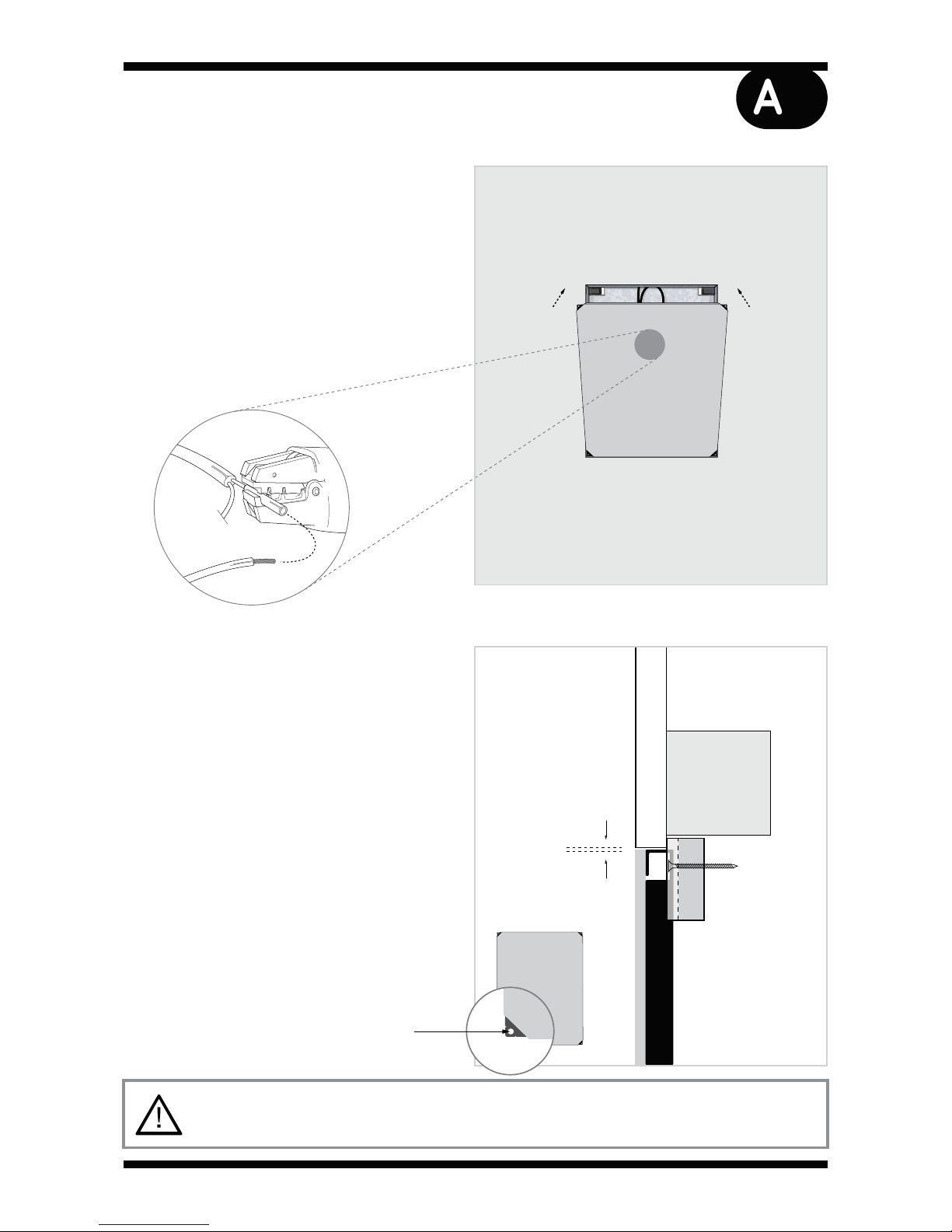
WARNING:
No attempt should be made to install this product within existing building structures unless you are certain
that no electric cables, water pipes, gas pipes or supporting joists will be cut through.