Ampac Fire Finder EN54-2 Guide

FireFinder

INCOMING ALARM CONDITION
1) INDICATION
FIRE LED STEADY
LCD DISPLAY OF DESCRIPTION
TYPE, ADDRESS, DATE TIME
AND NUMBER OF ALARMS
2) SOUNDER SILENCE OR SOUND EVACUATION
PRESS KEY
DISABLE ALARM
REPEAT THE ABOVE STEPS
AFTER PRESSING NEXT TO
DISABLE ALARMS
LCD DISPLAY OF DESCRIPTION
TYPE, ADDRESS, DATE TIME
AND NUMBER OF DISABLES
3) SOUNDER SILENCE
FIRE LED STEADY
IF NECESSARY PRESS TO
SILENCE SOUNDERS
INDICATOR WILL TURN ON
3) RESET ALARMS
PRESS TO RESETALLALARMS
DESCRIPTION
DATE TIME
LOOP No SENSOR No STATUS: ALARM
SENSOR ALARMS 1 OF xx
TYPE
LOOP No SENSOR No STATUS: DIS
DESCRIPTION
DATE TIME
SENSOR DISABLES 1 OF xx
TYPE
FIRE
SOUNDER
SILENCE EVACUATE
DEVICE
DISABLE / ENABLE
SOUNDER
SILENCE
RESET
FIRE

TABLE OF CONTENTS
Page No.
1Non Disclosure Agreement..................................................................................................1
2About This Manual ...............................................................................................................2
2.1 Introduction................................................................................................................2
2.2 General Requirements ...............................................................................................2
2.3 References.................................................................................................................2
2.4 Symbols.....................................................................................................................2
3System Overview....................................................................... Error! Bookmark not defined.
3.1 FACP Configuration Examples.................................... Error! Bookmark not defined.
4FireFinder Description .............................................................. Error! Bookmark not defined.
5Placing the Basic System into Operation................................. Error! Bookmark not defined.
5.1 Unpacking................................................................... Error! Bookmark not defined.
5.2 Anti-Static Precautions................................................ Error! Bookmark not defined.
5.3 Working On The System ............................................. Error! Bookmark not defined.
5.4 The Cabinet ................................................................ Error! Bookmark not defined.
5.5 Mounting The Cabinet................................................. Error! Bookmark not defined.
5.6 Operational Parameters .............................................. Error! Bookmark not defined.
5.7 Cabling Recommendations.......................................... Error! Bookmark not defined.
5.8 Power Supplies and AC Mains Installation................... Error! Bookmark not defined.
5.8.1 Connecting the Mains Earth............................. Error! Bookmark not defined.
5.8.2 Connecting the Mains Power to the Power SupplyError! Bookmark not defined.
5.9 Current Limiter, Fuse Board (BRD85CLFB1)............... Error! Bookmark not defined.
5.10 Brigade / PSU Monitor Board (BRD85BPMB).............. Error! Bookmark not defined.
5.10.1 Battery Connections (TB1)............................. Error! Bookmark not defined.
5.10.2 Auxiliary 27 Volt Power (TB2)........................ Error! Bookmark not defined.
5.10.3 Bell / Sounder Monitored Outputs (TB3 & TB5)Error! Bookmark not defined.
5.10.4 Relay Output Connections (TB6 –TB10)....... Error! Bookmark not defined.
5.11 Main Board (BRD86MBA)............................................ Error! Bookmark not defined.
5.12 Front Panel Board (302-690)....................................... Error! Bookmark not defined.
5.13 Main CPU (BRD85CPU).............................................. Error! Bookmark not defined.
5.14 Slave CPU (302-669) .................................................. Error! Bookmark not defined.
5.15 RS232 Modem / Programming / Debug Interfacing...... Error! Bookmark not defined.
5.16 Ancillary Services........................................................ Error! Bookmark not defined.
5.17 Conventional Zone Board (302-671B).......................... Error! Bookmark not defined.
5.18 Addressable Loop Termination Board (BRD86DLTB) .. Error! Bookmark not defined.
6Expanding the FACP with Compatible FireFinder Boards ...... Error! Bookmark not defined.
6.1 16/16 Input / Output Board (302-672) .......................... Error! Bookmark not defined.
6.2 8 Way Relay Board (302-6760/1)................................. Error! Bookmark not defined.
6.3 16 Way Input Board (302-677)..................................... Error! Bookmark not defined.
6.4Serial Relay Board (302-732) ...................................... Error! Bookmark not defined.
6.5 32 Zone LED Mimic Board (302-7000)......................... Error! Bookmark not defined.
6.6 External Control Interface Board (BRD85ECI) ............. Error! Bookmark not defined.
6.7 Valve Display Module (302-7160)................................ Error! Bookmark not defined.
6.8 8 Way Sounder Monitor Board (302-7170)................... Error! Bookmark not defined.

6.9 Sounder / Bell Control Board (302-7420/1).................. Error! Bookmark not defined.
6.10 Printer......................................................................... Error! Bookmark not defined.
6.10.1 Indicators and Buttons................................... Error! Bookmark not defined.
6.10.2 Maintenance.................................................. Error! Bookmark not defined.
6.10.3 Printer Connections and Jumpering............... Error! Bookmark not defined.
6.10.4 Printer 5 Volt Power Supply (BRD42PVCB1). Error! Bookmark not defined.
7Expanding the System Through Networking........................... Error! Bookmark not defined.
7.1 Communications: Controller Interface Board (302-7250)Error! Bookmark not defined.
7.2 Communications: Controller Interface Board (302-7240)Error! Bookmark not defined.
7.3 Expansion Board (302-688)......................................... Error! Bookmark not defined.
7.4 Expansion Controller (159-0077)................................. Error! Bookmark not defined.
7.5 Networking.................................................................. Error! Bookmark not defined.
7.6 Led Mimic Board (302-7150) ....................................... Error! Bookmark not defined.
7.7 Liquid Crystal Display Repeater Panel (302-7200)....... Error! Bookmark not defined.
8FireFinder Operation............................................................................................................3
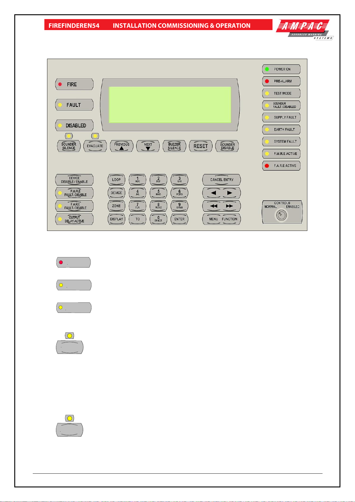
8.1 The Control Panel......................................................................................................3
9Functions And Menus..........................................................................................................7
9.1 The Default LCD Display............................................................................................7
9.2 Accessing Functions and Menus ................................................................................7
9.3 Function Menu and Access Levels .............................................................................7
9.3.1 Forgotten Passwords......................................................................................7
10 The Main Menu .....................................................................................................................8
10.1 Status Menu...............................................................................................................8
10.2 Testing Menu...........................................................................................................10
10.3 Sounders .................................................................................................................10
11 Main Functions...................................................................................................................11
11.1 Setting the Function Date Facility.............................................................................11
11.2 Setting the Function Time Facility.............................................................................11
11.3 Setting the Function Daynight Facility.......................................................................11
11.4 Function Logs Facility...............................................................................................11
11.5 The Function Test Facility.........................................................................................12
11.6 Function Manual I/O Control.....................................................................................13
11.7 Function Passwords.................................................................................................13
11.7.1 Forgotten Passwords..................................................................................14
11.8 Function Programming.............................................................................................14
11.8.1 Conventional Zone Programming................................................................14
11.8.2 Device Programming..................................................................................15
11.8.3 Input Programming.....................................................................................16
11.8.4 Output Programming..................................................................................16
11.8.5 Watchdog...................................................................................................16
11.9 Extra Devices Detected............................................................................................17
12 Incoming Fire Alarm Signal ...............................................................................................18
13 Accessing a Loop, Sensor or Zone ...................................................................................19
14 List Of Compatible Detectors.................................................... Error! Bookmark not defined.
15 Certification Information....................................................................................................20

16 Troubleshooting Chart.............................................................. Error! Bookmark not defined.
17 Address Setting......................................................................... Error! Bookmark not defined.
18 Glossary of Terms..............................................................................................................21
19 Definitions ..........................................................................................................................22
20 Qick Reference Guides ......................................................................................................23

Page 1
1 Non Disclosure Agreement
This contract has been entered into by the person or company user of this document (hereafter
called the Trader) and AMPAC Technologies (hereafter called AMPAC) of 7 Ledgar Rd, Balcatta,
Western Australia 6021 under the terms and conditions as specified hereunder.
Whereas AMPAC and the Trader for their mutual benefit and pursuant to a working relationship
which may be established, anticipate that AMPAC will disclose in the form of this document,
information of a secret, or confidential or proprietary nature (hereinafter collectively referred to as
Proprietary Information).
Whereas AMPAC desires to ensure that the confidentiality of any Proprietary Information is
maintained in accordance with the terms of this Agreement;
NOW, THEREFORE, in consideration of the foregoing premises, and the mutual covenants
contained herein, the Trader hereby agrees as follows:
1. The Trader shall hold in trust and confidence, and not disclose to any person outside its
organisation, any Proprietary information which is disclosed to the Trader by AMPAC under
this Agreement. Proprietary Information disclosed under this Agreement may be used by the
Trader only for the purpose of carrying out work on or with AMPAC supplied equipment and
may not be used for any other purpose whatsoever.
2. The Trader shall disclose Proprietary Information received by AMPAC under this Agreement
to persons within its organisation only if such persons are legally bound in writing to protect
the confidentiality of such Proprietary Information.
3. The undertakings and obligations of the Trader under this Agreement shall not apply to any
Proprietary Information which:
Is disclosed in a printed publication available to the public, is described in patent
anywhere in the world, or is otherwise in the public domain at the time of disclosure;
Is generally disclosed to third parties by AMPAC without restriction on such third
parties;
Is shown by the Trader to have been in its possession prior to the receipt thereof
from AMPAC;
Is approved for release by written authorisation of AMPAC; or
Is not designated by AMPAC in writing or by appropriate stamp or legend to be of a
secret, confidential or proprietary nature.
4. This Agreement will be binding upon and inure to the benefit of the parties hereto, and their
respective successors and assigns.
5. This Agreement, and all rights and obligations hereunder, shall expire on the 10th
anniversary of the date of issue of this document.
These terms are accepted by the Trader on receipt and retention of this document.

Page 2
2 About This Manual
2.1 Introduction
This manual contains all the information required to install, commission and operate the FireFinder
SERIES II Fire Alarm Control Panel (FACP) fitted with Version 6 software and is only available to
and for the use of personnel engaged in its installation, commissioning and operation.
2.2 General Requirements
The FireFinder Series II FACP has been designed and manufactured from high quality commercial
components so as to comply with major world standards. To ensure these standards are not
compromised in any way installation staff and operators should;
Be qualified and trained for the task they undertake;
Be familiar with the contents of this manual prior to the installation, commissioning or
operation of a FireFinder control system;
Observe anti-static pre-cautions at all times; and
Be aware that if a problem is encountered or there is any doubt with respect to the
operational parameters of the installation the supplier should be contacted.
2.3 References
FireFinder Technical Manual
ConfigManager
FireFinder Detector Manual
British Standard: EN54 parts 2 & 4
2.4 Symbols
Important operational information
Note: Configuration considerations
Observe antistatic precautions
Mains supply earth
DANGER mains supply present

Page 3
3 FireFinder Operation
3.1 The Control Panel
Figure 1: The SP1M FireFinder Control Panel
FIRE
FIRE (Red) –This LED will be illuminated steady if any fire alarms are present on the
system.
FAULT
FAULT (Yellow) –This LED will be illuminated steady if there are any faults on the
system, whether they are loop faults, module faults, device faults etc.
DISABLED
DISABLED (Yellow) –The LED will light steady if any detectors, devices or zones in
the system have been disabled or if an output relay has been de-activated. The display will show the
conditions as per EN54 9.2 and 9.4.2.
SOUNDER
SILENCE
SOUNDER SILENCE –Pressing this button will silence any Bells or Sounders (activated
either by a fire alarm, a manual evacuation or a manual alert) that are connected to the fire panel. If
the bells or sounders are silenced the LED just above the button will be illuminated steady indicating
that the sounders have been silenced and a sounder resound is available. If a manual evacuate or
manual alert condition is present when the Sounder Silence button is pressed, these conditions will
remain visible indicating the conditions are still present for resounding. A new Fire Alarm, manual
evacuate or manual alert will resound all the previously silenced Bells and Sounders. Pressing
Sounder Silence a second time while the Sounder Silence LED is illuminated, will also re-sound the
Bells and Sounders.
EVACUATE
EVACUATE –Pressing this button will activate the Sounders and Bells that have been
programmed for manual evacuation and the LED just above the button will be illuminated steady. If
the sounders have been previously silenced the LED above the Sounder Silence button will turn off
and the Sounders and Bells that were previously silenced will resound. This manual evacuate
condition can only be cleared by a Reset and will override a manual “Alert” condition.

Page 4
PREVIOUS
PREVIOUS –This button is used for scrolling backwards through fire
alarms, faults, or disablement’s displayed on the LCD.
NEXT
NEXT –This button is used for scrolling forwards through fire alarms, faults, or disables
displayed on the LCD.
BUZZER
SILENCE
BUZZER SILENCE –Pressing this button will silence the panel buzzer, which sounds
whenever there is a fire alarm or fault. The sound for a fire alarm is a steady sound where as for a
fault it is intermittent.
RESET
RESET –Pressing this button will reset the panel, clearing any fire alarms and taking the
LCD display back to its default screen, unless there are any un-cleared faults or disabled devices,
these will continue to be displayed. Pressing reset will also clear the manual evacuate, the manual
alert condition and the sounder silence condition.
Note: Pressing reset will not clear any disablements including Sounder Disable.
SOUNDER
DISABLE
SOUNDER DISABLE –This button is used to disable the Bells or Sounders. A new fire
alarm, manual evacuate or manual alert will not activate the Bells or Sounders while they are
disabled. If a fire alarm, manual evacuate or manual alert condition existed prior to the Sounder
Disable button being pressed, the conditions will remain present but the associated Bells and
Sounders will turn off. These Bells and Sounders will reactivate when the Sounder Disable button is
pressed a second time for re-enablement.
POWER ON
POWER ON (Green) –This LED will be illuminated when power is connected to
the FACP and switched on.
PRE-ALARM
PRE-ALARM (Red) –This LED will be illuminated when a sensor/detector is in
the pre-alarm state.
TEST MODE
TEST MODE (Yellow) –This LED will be illuminated when the panel is in any of
the test modes.
FAULT / DISABLED
SOUNDER
SOUNDER FAULT / DISABLE (Yellow) –This LED will flash when there is a fault
on the external sounder output. The LED will go steady if the sounder is disabled. If the sounder is
both in fault and disabled the LED will flash and then go steady in a cycle.
SUPPLY FAULT
SUPPLY FAULT (Yellow) –This LED will be illuminated when there is a supply
fault. The following conditions constitute a fault.
Mains power is not available.
The output voltage is too low.
The output voltage is too high.
The battery is not connected properly or has failed.
EARTH FAULT
EARTH FAULT (Yellow) –This LED will be illuminated if there is an earth fault (+
or -) on any of the signal cables of the system.
SYSTEM FAULT
SYSTEM FAULT (Yellow) –This LED will be illuminated if the main system CPU
is in fault.
F.W.R.E. ACTIVE
F.W.R.E (Fault Warning Routing Equipment) ACTIVE (Yellow) –This LED will be
illuminated when the FWRE output is active.

Page 5
F.A.R.E. ACTIVE
F.A.R.E (Fire Alarm Routing Equipment) ACTIVE (Red) –
This LED will be illuminated when the FARE output is active.
DEVICE
DISABLE / ENABLE
DEVICE DISABLE / ENABLE –This button is used to disable or re-enable
selected individual or groups of detectors, devices or zones.
F.W.R.E.
FAULT / DISABLE
F.W.R.E FAULT / DISABLE –Pressing this button will disable the FWRE output
relay on the Output board. If disabled the associated LED will be illuminated. Pressing the button
again will re-enable the FWRE relay. The LED will also be illuminated if the FWRE is in fault.
F.A.R.E.
FAULT / DISABLE
F.A.R.E FAULT / DISABLE –Pressing this button will disable the FARE output
relay on the Output board. If disabled the associated LED will be illuminated. Pressing the button
again will re-enable the FARE relay. The LED will also be illuminated if the FARE is in fault.
OUTPUT
DELAY ACTIVE
OUTPUT DELAY ACTIVE –Future option, not yet available.
LOOP
LOOP –Press this button followed by a number to select the loop you wish to access, e.g.
LOOP 4.
DEVICE
DEVICE –After selecting the Loop number using the LOOP button, press the DEVICE
button to enter the sensor number for the device you wish to interrogate.
ZONE
ZONE –Press this button followed by a number e.g. ZONE 4 to select the required zone.
DISPLAY
DISPLAY –Press this button after selecting the Zone number or the Loop and Sensor
numbers to display the status of the device.
8
WXYZ
THE ALPHA/NUMERIC BUTTONS –These buttons are used to navigate around the
panel’s menus and enter data. If you are entering a description, or some other data that contains
characters as well as numbers, pressing the buttons multiple times will scroll through the available
letters written on the button, in sequence.
TO
TO –Use this button to access a range of devices. E.g.
2
DEF
TO
7
TUV
.
ENTER
ENTER –Press the ENTER button when prompted to enter data.
CANCEL ENTRY
CANCEL –The CANCEL ENTRY button is used to delete any data in the current
field or return to the previously displayed menu.
SINGLE ARROW BUTTONS –These move the cursor on the LCD back and forth
when entering data into a field.
DOUBLE ARROW BUTTONS –These are used to move between fields when
entering data.
MENU FUNCTION
MENU / FUNCTION –Pressing the MENU button will display the main menu on
the LCD. Similarly pressing the FUNCTION button will display the function menu on the LCD.

Page 6
CONTROLS
NORMAL ENABLED
NORMAL –Normal day to day operation. ENABLED –
Access level 2.
Note: the key can only be removed in the NORMAL position.
LCD DISPLAY –
FIREFINDER 16/2/2007 14.31.15
AMPACEUROPELTD
PH: +44 (0) 1302 833 522
SYSTEMISNORMAL
AC:1S ALM: 000 PALM: 000 FAULT: 000 DIS: 000
AC:1S
=Access Level 1
Sensor Mode
ALM: 000
= Number of
Alarms present
PALM: 000
= Number of
Pre-alarms present
FAULT: 000
= Number of
Faults present
DIS: 000
= Number of
Disables present
Customer definedtext
Figure 2: LCD Default Screen
This screen can be configured with the servicing companies’ name and phone number. It also
displays the current date, time and if the system is normal (no faults and fire alarms).
If there are any faults or fire alarms the LCD will display the device/s in question and the time of the
1st fire alarm.

Page 7
IMPORTANT NOTE:
It is strongly recommended that all field programming changes be properly recorded.
4 Functions And Menus
4.1 The Default LCD Display
In its normal state the FireFinder™ will display a screen similar to that shown on previous page.
This screen can be configured with the servicing company’s name and phone number via a laptop or
modem. The current date, time is set in the Function menu while system status is automatically
displayed.
4.2 Accessing Functions and Menus
At Levels 2 and 3 access to the panel Functions are password protected.
A new panel has a pre-programmed password of 2222 for Level 2 and 3333 for Level 3. When the
customer takes control of the panel the password can be changed to suit their requirements.
Note: All menus are provided with screen prompts and a “Quick Reference Guide” (see Section
24) guides the operator through the operation of the FACP .
MENU FUNCTION
From the DEFAULT DISPLAY, press MENU or FUNCTION. The FUNCTION menu is
password protected (actually a pass-number as it can only contain numbers) to prevent unauthorised
changes to the panel's configuration.
4.3 Function Menu and Access Levels
Three levels of ACCESS are available. Level 1 has access to MENU only while Password protected
Levels 2 and 3 access MENU and FUNCTION as listed below. (Also see the Quick Reference
Guide, Section 26)
Level II: Allows access to:
Date: Enter the Day, Month and Year (4 digit year).
Time: Enter the hours and minutes (24 hour mode).
Day/Night Settings: Enter the Day / Night ON times and Enable - Disable.
Logs: Fire Alarm, Fault, Isolate, System & Input / Output logs.
Tests: Walk and loop tests.
I/O: Sets the functionality of Input / Output devices.
Access: Password entry to Level 3
Level III: In addition to the Level I & II facilities, Add, Delete, Delete all passwords and Mode (Zone /
Sensor) onsite Programming.
4.3.1 Forgotten Passwords
Follow the following process if a password has been forgotten or misplaced;
Entering 9999 into the password field;
Take note of the 4 digit password number displayed on the screen; then
Contact the AMPAC head office and quote the above number;
A temporary password will be issued and a new password can then be programmed into the FACP.
Note: The temporary password becomes invalid if 9999 is entered again or if the panel is re-
powered after 9999 has been entered.

Page 8
5 The Main Menu
The MAIN MENU is accessed by pressing MENU.
Figure 3: The Main Menu
While in the MAIN MENU press the appropriate number on the keypad to view any;
FIRE ALARMS,
PRE-ALARMS,
FAULTS; Pressing brings up a sub-menu from which a more detailed description of a
fault can be displayed. Select a field 0 –7.
Note: Comms will only be available for a networked panel.
Zones
Sensors
Loops
Modules
Comms
Power
Supply
Brigade
Test
Failures
Sounders
DISABLES on the system.
If there are no fire alarms, pre-alarms, faults or disables, a message to that effect will be displayed
for approximately 1 to 2 seconds and then the display will return to the Main menu.
5.1 Status Menu
Figure 4: The Status Menu (Non networked Panel)
Is pressed to access the STATUS MENU.
From the STATUS MENU the status of all of the system components and settings listed below can
be interrogated.
Press;
Loops: Enter the loop number and it will display its status.
Modules: If pressed the following sub-menu will be displayed.
Slave
Power Supply
Brigade (Outputs)
External LED Mimic
E.g. Pressing Power Supply :This menu item will display the charger voltage, whether or not the
power supply is in fault, if Mains is available and if the battery is correctly fitted.
I/O: The LCD will display the status of an input or output in a panel or a loop.
Enter (i) the I/O controller number then the input or output on that controller or, (ii) the loop and
sensor number and the output on that device.
Once entered the LCD will then display a description of what that input or output does and its current
state.
STATUS MENU
0: LOOPS 1 :MODULES 2: I/O
3 :SYSTEM 4: AVALUES
SELECT NO.
AC: 3S ALM: 000 PALM: 000 FLT: 000 DIS: 000
MAIN MENU
0: ALARMS 1 :PREALARMS 2: FAULTS 3: DISABLES
4:STATUS 5 :TEST 6: SOUNDERS 7: PRINTER:
SELECT NO.
AC: 2S ALM: 000 PALM: 000 FLT: 000 DIS: 000

Page 9
Networked Panel –ONLY
Figure 5: Display Network Status)
Is pressed to access NETWORK STATUS.
Figure 6: Display Network Points
Network Points:
Network LCD Screens are:
Press Status
or Power Supply
or Brigade
Select network point
Charger volts
Operational
E.g. Loop number
Battery Detected
Non- Op
Mains OK
Remote Slave Modules:
Select from Network Status, Remote Slave Modules then Module No then ENTER .
Figure 7: Display Remote Slave Modules
Remote External LED Mimic Modules:
Select from Network Status, Remote External LED Mimic Modules then, NP number then, ENTER
then, External LED Mimic number then, ENTER .
System:
Is pressed to access SYSTEM STATUS - for a network panel
Figure 8: Display System Status
Apollo Loop 1
TYPE: APOLLO LOOP NO: 1 VER: 6.1
NP: 1 MOD: 4 STAT: NORMAL
REMOTE MODULE STATUS
AC: 2S ALM: 000 PALM: 000 FLT: 000 DIS: 000
DISPLAY NETWORK POINTS
0: STATUS 1: POWER SUPPLY 2: BRIGADE
SELECT NO.
AC: 2S ALM: 000 PALM: 000 FLT: 000 DIS: 000
DISPLAY NETWORK STATUS
0: NETWORK POINTS 1: REMOTE SLAVE MODULES
2: REMOTE EXTERNAL LED MIMIC MODULES
SELECT NO.
AC: 2S ALM: 000 PALM: 000 FLT: 000 DIS:
000
SYSTEM STATUS
ALARMS: 0000 PRE-ALARMS: 0000 DISABLES: 0000
DEVICE FAULTS: 0000 MOD FAULTS: 00 WDG: 00
LOOP FAULTS: 00 VERSION: 6.1 EN54
AC: 2S ALM: 000 PALM: 000 FLT: 000 DIS: 000

Page 10
A values:
, for a network panel is pressed to access AVALUES. Enter the Loop number then ENTER
then Sensor number then ENTER .
Figure 9: Analogue Values
5.2 Testing Menu
Is pressed to access the TESTING MENU. From here the following can be tested:
Figure 10: The Testing Menu
Alarm Test
Alarm tests either a selected zone or a sensor or a range of zones or sensors.
(This test will force a sensor to go into Alarm or a conventional zone to a simulated Alarm State)
Fault Test
Fault tests either a zone or a sensor or a range of zones or sensors.
(This test will force a sensor to go to the Fault State or a conventional zone to a simulated Fault
State)
Once the above tests have been completed the TEST COMPLETE screen will appear. Each ALARM
and FAULT that was detected can be viewed by scrolling through them using the NEXT and
PREVIOUS buttons.
Lamp Test
Will flash the LED’s in sequence on the front panel and illuminate the various segments on the
LCD display.
5.3 Sounders
Press
To select Sounders then to enable / disable as required.
Printer Menu
Press
To select the panel printer ( if installed ) then to forces it to Go ON or OFF Line while sets
the printer to an alarm mode operation only.
Loop 1 sensor 1
L1 S1 Z2 STAT: NORMAL
AVALUE: 25 MODE: 0 I: 000 O:: 000
AC: 2S ALM: 000 PALM: 000 FLT: 000 DIS: 000
TESTING MENU
0: ALARM 1: FAULT 2: LAMP
SELECT NO.
AC:3S ALM: 000 PALM: 000 FLT: 000 DIS: 000

Page 11
6 Main Functions
Figure 11: The Level III Functions Menu
6.1 Setting the Function Date Facility
Select FUNCTION. A prompt will ask for a PASSWORD if the control panel is not currently active.
Using the keypad key in the PASSWORD and press ENTER.
Press
To select the set DATE SCREEN. The prompt will ask for the date to be entered in this format,
DD/MM/YYYY (EG 16/02/2007), key in and press ENTER. The screen will then return to the MAIN
FUNCTIONS MENU.
6.2 Setting the Function Time Facility
Press
Then in the following format key in the time, HH:MM using the 24 hour mode. Press ENTER and
the screen will return to the MAIN FUNCTIONS MENU.
6.3 Setting the Function Daynight Facility
Press
The DAY-NIGHT SETTINGS screen will appear.
Press
To enter the DAY ON time then ENTER and,
To enter the NIGHT ON time then ENTER.
To enter this mode the function must be ENABLED, press Re-pressing will DISABLE the
DAYNIGHT function.
6.4 Function Logs Facility
Press
And the EVENT LOG MENU will appear.
The LOGS MENU function allows the operator to select and view the events of all;
Press
ALARMS
FAULTS
DISABLES
The date and time of the ALARM, FAULT or DISABLE as well as the device information will be
displayed. This screen also allows the operator to select two other facilities;
Press
PRINT ENTRY If a printer is installed pressing will print out the displayed information, or
SHOW OPTIONS by pressing
LEVEL III MAIN FUNCTIONS
0: DATE 1: TIME 2: DAY/NIGHT 3: LOGS
4: TESTS 5: I/O 5: PASSWORD 6: PROG
SELECT NO.
AC: 3S ALM: 000 PALM: 000 FLT: 000 DIS: 000

Page 12
This screen allows the operator to view the Logs by pressing to VIEW BY
ENTRY NUMBER or by pressing to VIEW BY DATE. In each case the screen will ask for the
appropriate information (ENTRY NUMBER or DATE) to be entered before anything can be
displayed.
Note: it is possible to scroll through the Logs by using
PREVIOUS
and / or
NEXT
6.5 The Function Test Facility
Press
The resulting screen is the TESTING MENU and prompts the operator to select the type of test they
wish to perform, for the WALK test ( also known as the Single Person Operational Test [SPOT] )
and for the LOOP test.
Press
WALK TEST; again the operator will be prompted to select either a
ZONE (press ) or SENSOR (press ) TEST.
ZONE WALK TEST MENU;
This screen requires the operator to select a Zone or number of Zones to be tested, that is enter the
Zone number and press ENTER or enter the Zone number press TO then the next highest Zone
number to be tested EG. 2 TO 7 then ENTER.
The TEST MODE LED will be illuminated for the duration of the test and the test will run until the
operator RESETS the system.
SENSOR WALK TEST MENU
This screen requires the operator to select a Zone and then a Sensor or number of Sensors ( using
the TO key ) to be tested then pressing ENTER to start the test.
The TEST MODE LED will be illuminated for the duration of the test and the test will run until the
operator RESETS the system.
Press
LOOP TEST requires the operator to select a LOOP for DIAGNOSTIC TESTING
Entering the LOOP number and pressing ENTER will initiate the DIAGNOSTIC TEST.
Note: The LED’s on the Brigade Board will indicate which leg is being tested.
The tests displayed are;
TESTING SIDE A IDENTIFYING DEVICES on SIDE A, and
TESTING SIDE B IDENTIFYING DEVICES on SIDE B.
Once the testing is completed the final screen will display the number of devices found and tested on
the LOOP.
Note: If the data is not entered within 2 minutes the screen will time out and return to the
DEFAULT SCREEN.

Page 13
6.6 Function Manual I/O Control
Press
To display the Manual I/O Control menu
Figure 12: The Manual I/O Control Menu
MANUAL I/O CONTROL
Press
Input Selected:
Press
IN A PANEL: Enter the I/O Controller number then the input number, this will display the
description for the input and its current state, you can then turn the input on or off or remove manual
control.
ON A LOOP: Enter the loop number, the sensor number and the input number. This will
display the description for the input and its current state, you can then turn the input on or off or
remove manual control.
Remove All Manual Input Control: Will remove all manual input control.
Output Selected: Same sequences as above for inputs but substitute outputs for Inputs.
Remove All Manual Control Selected: Globally removes all manual control.
6.7 Function Passwords
Press
While in the Main Functions menu (if your password gives you access) to display the Password
Menu.
Figure 13: The Password Menu
Press
Add Password: Enter the new password, then press ENTER. The password is always a 4
digit number.
Delete Password: Enter the password that you want to delete, then press ENTER.
Delete All Passwords: This asks you to confirm that you want to delete all the passwords.
Press ENTER then ENTER again.
MANUAL I/O CONTROL
0: INPUT 1:OUTPUT
2: REMOVE ALL MANUAL CONTROL
SELECT NO.
AC: 3S ALM: 000 PALM: 000 FLT: 000 DIS: 000
PASSWORD MENU
0: ADD PASSWORD 1 :DELETE PASSWORD
2: DELETE ALL PASSWORDS
SELECT NO.
AC: 4S ALM: 000 PALM: 000 FLT: 000 DIS: 000

Page 14
6.7.1 Forgotten Passwords
If you have forgotten your password,
1. enter 9999 into the password field;
2. Take note of the 4 digit password button displayed on the screen;
3. contact the AMPAC head office and quote this number;
4. a temporary password will be issued to allow access to the level 3 functions
5. A new password can now be programmed.
Note: The temporary password will become invalid if 9999 is entered again or if the panel is re-
powered.
6.8 Function Programming
Press
To display the Programming Menu.
Figure 14: The Programming Menu
6.8.1 Conventional Zone Programming
Press
Zone:
Key in the zone number and enter or change the description (DESC) by pressing the numeric
buttons multiple times to access characters while at the same time using the
buttons to move the flashing underline or cursor.
Figure 15: Zone Descriptions & Type Programming
Press to move to the TYPE field or edit the information.
Press to move between fields use the reciprocal button
By going through all the fields a second screen can be accessed to show the Output options.
Press to step through these fields
ON SITE PROGRAMMING MENU
0: CONV ZONE 1 :DEVICE 2:INPUT 3: OUTPUT
4: PANEL BASED MCP
SELECT NO.
AC: 3S ALM: 000 PALM: 000 FLT: 000 DIS: 000
EDIT Zx DESC AND TYPE STRINGS
DESC < ZONE >
TYPE<
ALPHA KEYS ARE ACTIVE
AC: 3S ALM: 000 PALM: 000 FLT: 000 DIS: 000

Page 15
Figure 16: Brigade Options
These keys are used to set the Y/N field that is the selected Zone that will
activate the Brigade options ALRM, bell etc. and Config.
Figure 17: Zone Configuration Latching / Non-Latching
Configuration settings are latching, Non-Latching, AVF and Self Reset (0 to 99 seconds).
Use or to change the latching setting
After setting the Configuration the ZONE, I/O GROUPS are then programmed.
Figure 18: Zone I/O Groups
After scrolling through the groups and entering what I/O GROUPS will be turned on by WHAT
MODULE OR DEVICE IN A ZONE the operator is prompted to press ENTER to confirm the entries
and / or changes.
6.8.2 Device Programming
Press
DEVICE:
Use these keys to EDIT and move through wording & numbering.
Use these keys to MOVE between fields i.e.: DESC & TYPE and NEXT
PARAMETER SETTING.
Screen:
Enter the Loop and Sensor number then scroll through the following screens.
Press or Press
To EDIT or to DELETE
EDIT LxSx DESCRIPTION AND TYPE STRING. After each step press
EDIT ZX BRIGADE OPTIONS AND CONFIG
ALRM: Y/N BELL: Y/N AUX: Y/N SPRK: Y/N AIF: Y/N
ALARM LED: Y/N CONFIG: LATCHING
Use < or > to change setting
AC: 3S ALM: 000 PALM: 000 FLT: 000 DIS: 000
EDIT Z CONFIGURATION
CONFIG: LATCHING
Use < or > to change alarm setting
AC: 3S ALM: 000 PALM: 000 FLT: 000 DIS: 000
EDIT Z I/O GROUPS
GROUP1: GROUP2: GROUP3:
GROUP4: GROUP5: GROUP6:
Enter GROUP NO.
AC: 3S ALM: 000 PALM: 000 FLT: 000 DIS: 000
This manual suits for next models
2
Table of contents
Other Ampac Control Panel manuals

Ampac
Ampac ZoneSense Plus Guide

Ampac
Ampac FireFinder Series II AS442 User manual

Ampac
Ampac ZoneSense Plus Guide

Ampac
Ampac NZ100 Series Guide

Ampac
Ampac LoopSense User manual

Ampac
Ampac EV3000 4210-0030 Guide

Ampac
Ampac FireFinder II Series Instruction Manual

Ampac
Ampac ZoneSense Product guide

Ampac
Ampac FireFinder LED Mimic User manual

Ampac
Ampac LoopSense EN54.2 User manual