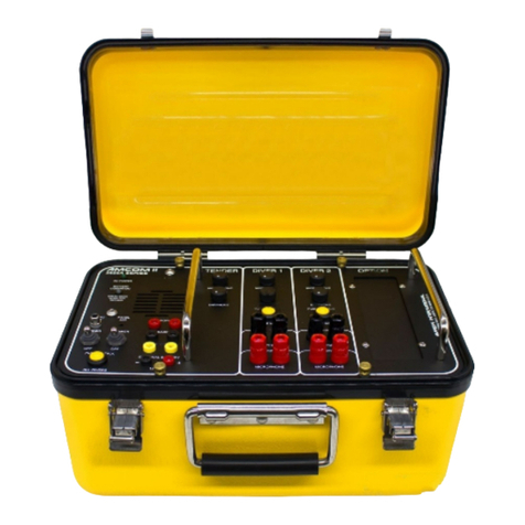
Amron 2810A-2001 User manual

INSTRUCTION MANUAL
FOR
AMRON INTERNATIONAL DIVING SUPPLY, INC.
MODEL 2810A-2001
Single Lock Chamber Communicator
S/N _____________________
This manual and the information contained herein is provided for use as an operation and
maintenance guide. No license or rights to manufacture, reproduce, or sell either the manual or
articles described herein are given. AMRON INTERNATIONAL DIVING SUPPLY, Inc. reserves
the right to change specifications without notice.
Amron International Diving Supply, Inc.
1380 Aspen Way
Vista, California 92081 U.S.A
PHONE (760) 208-6500
FAX (760) 599-3857
Email: [email protected]
www.amronintl.com
Copyright © 2005, AMRON INTERNATIONAL, INC.
Revised August 2010

TABLE OF CONTENTS
Specifications 1
Electrical........................................................................................................................1.1
Mechanical....................................................................................................................1.2
General Information 2
Options & Accessories 3
Warranty and Service Policy 4
Limited Warranty...........................................................................................................4.1
Service Policy................................................................................................................4.2
Controls and Connections 5
Operation 6
Theory Of Operation 7
Theory Of Operation .....................................................................................................7.1
Amplifier Card 2811B-200.............................................................................................7.2
Audio Output Volume Controls......................................................................................7.3
Battery Charger Card, 2324-202...................................................................................7.4
Maintenance & Trouble Shooting 8
Chamber Radio Field Check Procedures .....................................................................8.1
Quick Simulcom Check ................................................................................................8.2
Comprehensive 2-Wire and Simulcom Check .............................................................8.3
Problems And Their Possible Causes...........................................................................8.4
Drawings & Schematics 9
General .........................................................................................................................9.1
Parts Layout 2811B-200 ...............................................................................................9.2
Parts Layout 2324-202..................................................................................................9.3
Front Panel 2810A-2001...............................................................................................9.4
Schematic 2810A-2001.................................................................................................9.5
Parts Identifier- Front Panel Model 2810A-2001...........................................................9.6
Mounting Detail Model 2810A-2001..............................................................................9.7
I

TABLE OF CONTENTS
II
Parts List 10
General Information ....................................................................................................10.1
2810A-2001 Chamber Communicator ........................................................................10.2
2811B-200 PC Card Assembly...................................................................................10.3
2323-6002 Charger Chassis Assembly.......................................................................10.4
2824-202 Power Supply PC Card Assembly ..............................................................10.5
2810A-FS Field Spares Kit..........................................................................................10.6
2810A-SS Shop Spares Kit.........................................................................................10.7

SPECIFICATIONS
1
ELECTRICAL 1.1
Input Impedance (Each Input)...........................................................................100 Ohms
Frequency Response..................................................................................650 - 2200 Hz
Common Mode Rejection.........................................................................................40 dB
Current Drain Maximum Full Volume.................................................................... 3 Amps
Typical Quiescent........................................................................................... 110 mAmps
Minimum Load Impedance.......................................................................................1 ohm
External Power Supply Voltage.....................................................115/230 VAC 50/60 Hz
Internal Power Supply Voltage..................................................................12 VDC Nominal
Operational Supply Voltage ...................................9 Volts Minimum - 18 Volts Maximum
Sensitivity (Input).......................................................................................................1 mV
Output Power (RMS @ 4 OHM Load, 14 VDC).................................................... 20 Watts
Battery Life, Model 2810A-2001..........................................................................50 Hours
DC Circuit Operating Voltage................................................................................12 VDC
MECHANICAL 1.2
Panel..........................................................................................................Stainless Steel
Enclosure ............................................................................... Black Anodized Aluminum
Width.....................................................................................................10.75 in. (27.3cm)
Chassis Clearance Depth .......................................................................7.00 in. (17.7cm)
Height......................................................................................................6.75 in. (17.2cm)
Weight With Batteries
Model 2810A-2001..................................................................................11.5 Lbs. (5.1kg)

GENERAL INFORMATION
2
GENERAL INFORMATION 2.1
The Amron International AMCOM Model 2810A-2001 is a panel mounted chamber communication
system operating from an internal 115/230 VAC power source with an internal 12 VDC battery
back up. The system is designed to provide voice communications between the chamber operator
and occupants within the chamber.
The 2810A-2001 has the capability of 2-wire and/or “Simulcom” (4-wire) communication modes.
Two-wire and Simulcom (4-wire) modes can be used simultaneously. This enables the user to
operate in a hands free mode, using a headset and communicate between the chamber and
operator without having to use the push-to-talk.
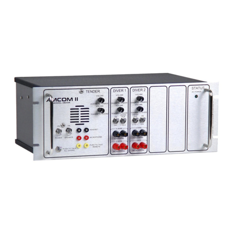
The AMCOM I Chamber Communication System is a full-featured hard wire, single lock
communication system. The AMCOM I has independent volume controls (operator and lock). The
2810A-2001 can be used with a hand held microphone, which incorporates automatic talk back
speaker cut out. This feature greatly reduces the amount of background noise, and under noisy
conditions can make the difference between good or unacceptable sound and speech clarity.

OPTIONS & ACCESSORIES
OPTIONS & ACCESSORIES 3.1
1. Model 2821-28 AMRON remote walk-and-talk for deluxe headset with push-to-talk belt
module, banana jacks 25 feet 1/4" OD cable. - allows operator to use the push-to-talk
function from a belt module while connected to a 25’ extension on the headset. This is a
2-wire configuration. Custom lengths are available.
2. Model 2822-28 Amron Headset Extension (Simulcom - 4-wire) belt module with 25 feet of
1/4" O.D. cable - allows operator to talk freely on Simulcom while connected to a 25’
extension on the headset. Custom lengths are available.
3. Model 2460-28 headset with boom microphone, dual banana plugs. For operator.
4. Model 2460-31R headset with boom microphone, single XLR connector. For occupant.
5. Model 3113 Chamber Speaker. Includes talkback speaker, XLR headset jack and MS
mating connector.
6. Model 2405-28 Hand Held Push-To-Talk “noise canceling” microphone.
3

WARRANTY
WARRANTY 4.1
AMRON INTERNATIONAL DIVING SUPPLY, INC. warrants that its products are free from defects
in material and workmanship under normal use and service, as described in AMRON
INTERNATIONAL DIVING SUPPLY, Inc. literature covering this product, for a period of 90 days
from date of shipment. Amron’s obligations under this warranty are limited to the repair of or
replacement, at AMRON’S option, of defective materials. This warranty shall not cover defects,
which are the result of misuse, negligence, accident, repair or alterations.
SERVICE POLICY 4.2
Every effort will be made to assist in solving your problem. Equipment which must be returned to
the factory for repairs and should be safely packaged, insured, and shipped prepaid to:
AMRON INTERNATIONAL, INC.
1380 ASPEN WAY
VISTA, CA. 92081
Be sure to include the following information:
YOUR NAME (COMPANY NAME)
SHIPPING ADDRESS
PHONE NUMBER
CONTACT NAME
Please provide a brief description of the problem.
Valid in-warranty repairs will be made at no charge. A written estimate of repair charges will be
provided for out-of-warranty repairs before any work is done.
4

CONTROLS & CONNECTIONS
CONTROLS & CONNECTIONS 5.1
Before using the AMCOM I series diver communications system, you should familiarize yourself
with its operating controls and connections. Improper use of controls and connections will deprive
the user of the full benefit of this communication system.
A. Operator Controls
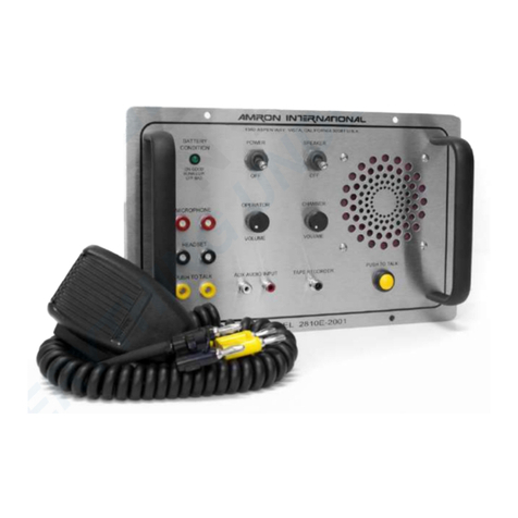
POWER Switch - Applies power to the unit.
SPEAKER Switch - Turns Speaker On/off. It may be necessary to turn speaker off when using a
headset to prevent feedback.
PUSH TO TALK Switch - Allows operator to chamber communication in 2-wire mode.
VOLUME OPERATOR - Controls amplification of operator’s microphone, therefore operator’s
volume to chamber
VOLUME CHAMBER - Controls amplification of chamber’s microphone, therefore chamber’s
volume to operator
B. Operator Connections
HEADSET - (INPUT/OUTPUT) - Is a dual banana jack (color coded black) connection for headset
earphones or external remote speaker. In 2-wire operation both headset microphone and
earphones are plugged into this jack, conversations (up-link & down-link) are switched
automatically when push to talk switch is actuated. In Simulcom (4-wire) operation this jack is
listening only, both up-link and down-link conversations are heard.
PUSH TO TALK - (INPUT) - Is a dual banana jack (color coded yellow), connection for remote
keying of push to talk. Single contact closure, 2-wire, close for down-link, open for up-link.
MICROPHONE - (INPUT) - Is a dual banana jack (color coded red) connection for
headset/microphone.
BATTERY CONDITION - INDICATOR, on steady indicates the presence of power, and a charged
battery. When the battery condition indicator blinks, the battery is low, and will need charging
soon. At the time when the indicator first begins to blink there are approximately 3 hours of
operating time remaining. When the indicator does not come on, battery voltage is below the point
at which reliable operation can be guaranteed. The first function to fail because of low voltage will
be the down link communication in 2-wire operation. Operator can hear chamber but chamber can
not hear operator.
HAND HELD MICROPHONE (Optional) with push-to-talk function. Actuation of hand held
microphone automatically disconnects the talk back speaker cutting out all background noise.
TAPE RECORDER Output signal for diving external recorder. Output level is factory set for 100
millivolt p-p.
5


OPERATION
OPERATION 6.1
The AMCOM I Model 2810A-2001 has the capability of 2-wire and/or Simulcom (4-wire) operation.
A. 2-Wire Operation
Connect the cable from the 2810A-2001, Red dual banana jack on the rear panel of the
communicator to the Chamber Comm. Box Model 3111 or equivalent. Chamber communicator will
monitor the chamber. The operator will hear all sounds in the vicinity of the Model 3111. Operator
must press the push-to-talk switch to talk to the chamber. This can be done by pushing the switch
and speaking into the speaker.
A better and more comfortable method is to use the optional hand held push-to-talk microphone.
You may also use a headset with either of the push-to-talk switches. If you are using the AMRON
Remote Walk & Talk Model 2821-28, the operator may press the push-to-talk switch on the belt
module.
B. Volume Controls
Chamber Volume Control - Adjusts the gain of the amplifier for the chamber microphone, thereby
adjusting volume the operator hears.
Operator Volume Control - Adjusts the gain of the amplifier for the operator's microphone, thereby
adjusting the volume to the chamber.
C. Simulcom (4-wire) Operation
Connect the cable from the 2810A-2001, red and black dual banana jacks on the rear panel of the
communicator to the Chamber Comm. Box Model 3111 or equivalent. Connect a headset (2460-
31R) to the Model 3111.
Connect operator headset (2460-28) earphones to “Headset” (input) and headset microphone to
"Microphone” (input). Turn speaker off to avoid acoustic feedback. Operation with speaker is
possible; by extending operator’s headset away from the speaker using the Headset Extension
Cable (25 foot). Note: It is not necessary to use the “Push-To-Talk” switch when operating in the
Simulcom Mode.
Operating the PTT switch will establish a priority channel for communication. “PTT” cuts out the
chamber’s microphone and prevents the chamber from talking. This allows the ability to establish a
clear channel of communications.
6

THEORY OF OPERATION
THEORY OF OPERATION 7.1
Refer to the diagrams and schematics while reading this section. This Section describes the
function of the electronic circuits.
AMPLIFIER CARD 2811B-200 7.2
Signal input
U2A and U2B are differential input amplifiers that accept dynamic microphone level signals (1 to
10mv.) and amplify them. Signals common to both inputs are rejected, common mode rejection,
(CMR).
Filter
U2C is an active passband filter and mixer that filters the speech waveforms for amplification and
clarity and sums the operator and chamber signals together.
Audio Power Amplifiers
The audio power amplifier, U2, is connected in a single ended configuration. The output "floats" at
approximately 6 volts and should never be connected to ground. The amplified audio output signal
is directed to the Chamber & Operator through relays K2 and K3.
Bias Level
Resistor R21 and voltage reference D2 determine the bias voltage for the amplifiers U1 and U2. It
should be 5.1 volts measured to ground +/- 5%.
Push to Talk and the Speaker Disconnect Relay
K1 is activated when a short circuit is applied to the yellow push to talk jacks on the front edge of
the case. This activates the push to talk circuitry, but also disconnects the speaker. The result is
superb clarity when using a hand held microphone to talk and the speaker to listen. When the
push to talk button on the front panel is used the speaker remains connected and may be used as
a microphone.
Battery Voltage Senses Circuit – U1 is used to electronically sense the battery voltage.
Controls the panel LED (battery condition indicator) that indicates operational status:
Good battery voltage ......................steady green light
Low battery ......................blinking green light
Below reliable operational range ......................off
7

THEORY OF OPERATION
8
AUDIO OUTPUT VOLUME CONTROLS 7.3
Volume Control
The filter output signal is attenuated through operator volume control R101 and chamber volume
control R103. This adjusts the signal going to the power amplifier U2 via C9 & C15.
2-Wire Operation
Input audio signals from the chamber are amplified and directed to the operator's headset and
speaker through relays K2 and K3. When the operator actuates the push to talk switch, operator's
speaker and headset are connected through relay K1 to microphone input. Chamber’s red jacks
are connected to audio output through relay K2.
Simulcom (4-wire)
Operator and chamber microphones are connected to amplifier inputs at all times. Operator
headset and chamber earphones are connected to audio output at all times.
BATTERY CHARGER CARD, 2324-202 7.4
The 2324-202 converts the AC power to a regulated DC voltage to operate the unit and charge the
batteries. The charger card consists of Primary and Secondary Circuits, these two separated
circuits are connected together through step down transformer.
This charger has a high level of insulation between Primary and Secondary circuits to prevent AC
line to pass to the amplifier circuit in order to protect divers from electric shock. The creepage
distance and air clearance on the charger meet UL2601-1 Medical Electrical Equipment
requirements. The transformer is split bobbin with high insulation between primary and secondary
winding.
The primary circuit detects AC line voltage (115 or 230), then activates latching relays K1 & K2 to
select the proper transformer primary winding connections. On the primary circuit there are two
micro fuses, F1&F2 (400mA 250 Volt), that have been mounted in socket holders. The fuses are
small round cylinders about the size of a pencil eraser mounted next to the AC cord connection,
about the size of a pencil eraser. The fuses are a single-use safety device. They interrupt the
current in the event of a massive short circuit. Consequently, a qualified technician should
thoroughly investigate the cause of a blown fuse. The unit should be examined for the cause of the
failure, and its safe operation verified before replacing the fuse and returning the unit to the field.
The secondary circuit receives low voltage (20V AC) from transformer secondary winding then
regulates the voltage at 14V DC. It automatically reduces the output voltage, in order to limit the
maximum output current for charging the battery. It is designed to properly charge the internal
battery without getting damage when battery is completely drained to zero. It protects batteries
from overcharge by automatically switching to float charge of 13.8 To 14.0 volts when batteries are
fully charged. The secondary circuit provides low current to power front panel LED which indicates
AC power is applied to unit.
There is a fuse, F3, in the secondary circuit located next to J2. If accidental reversing of internal
battery terminals occurs, the fuse will blow to protect the electronic circuits and wires from
damage. F3 fuse is replaceable with 3.15A-250V Slow Blow Micro Fuse.

MAINTENANCE
CHAMBER RADIO FIELD CHECK PROCEDURES 8.1
The following procedures are a step-by-step procedure to do a functional check of your radio,
using only a headset. These steps check all communication functions of the radio in both 2-wire
and Simulcom modes. This means that if your radio checks with these steps, any communication
problems must be somewhere else in the system, such as umbilical connections, speakers, and/or
microphones.
QUICK SIMULCOM CHECK 8.2
This brief procedure checks chamber radio functions in Simulcom: set all volume controls at mid-
scale, turn unit on.
Identify headset microphone lead and headset earphone lead. If required, plug into dual
banana jack adapters. (Usually the microphone plug is red.)
Plug in headset microphone to operator’s microphone input (red jacks, front panel) and
headset earphone to operator’s headset input/output (black jacks, front panel). You should be
able to hear yourself talk. Adjust Operator Volume knob and verify sound goes up and down.
This verifies operator circuit.
Move headset microphone to chamber microphone input (red jacks, rear panel) and headset
earphones to chamber earphone output (black jacks, rear panel). You should be able to hear
yourself talk. Adjust Chamber Volume knob and verify sound goes up and down. This verifies
chamber circuit.
The basic Simulcom function of the chamber radio has now been checked.
9

MAINTENANCE
COMPREHENSIVE 2-WIRE AND SIMULCOM CHECK 8.3
Set all volume controls at mid-scale; turn power on.
Operator circuit check
Identify headset microphone lead and headset earphone lead. If required, plug into dual banana
jack adapters. (Usually the microphone plug is red.)
Plug in headset microphone to Operator’s Microphone (input, red jacks, front panel) and headset
earphone to Operator’s Headset (input/output, black jacks, front panel). Turn speaker off, power
on. Put on headset and speak into microphone, listening for your own voice. Adjust Operator to
Chamber volume, and check that controls respond and there is adequate volume. If you can talk
to yourself, then Operator circuit is operating properly.
Chamber’s down-link check
Now move headset earphone plug from Operator’s Headset (input/output, black jacks, front panel)
to Chamber’s Microphone (input, red jacks, rear panel). Talk into headset while pressing Push To
Talk switch. You should be able to talk to yourself with plenty of volume as long as the "Push To
Talk" switch is depressed. This verifies 2-wire communication from Operator to Chamber and the
function of relays.
Operator's speaker downlink check
Unplug headset from Microphone (input) and turn Speaker on. Press Push To Talk and talk into
speaker. You should hear yourself in headset earphones. This verifies speaker section. Turn
speaker off.
Chamber’s up-link check
Place headset microphone into Chamber‘s Microphone (input, red jacks, rear panel) and headset
earphone plug in Operator’s Headset (input/output, black jacks, front panel). Talk into
headset. You should hear yourself in the headphones with plenty of volume.
10

MAINTENANCE
PROBLEMS AND THEIR POSSIBLE CAUSES 8.4
General
Amron has many units that have been in hard use for over a decade. The primary cause for
complete failure of a unit is corrosion from salt water that has been allowed to continuously seep in
after a unit is no longer watertight. If your LED has been pushed in, gasket deteriorated or
speaker punctured you should attend to repairing them promptly.
Unit not operating
A great number of problems are very simple failures and can often be found by a very careful and
close inspection of the unit or system. Logical deductions and equipment familiarity can often
reduce the suspected area to just one component or circuit. Often upon examination clues are
revealed which can also aid in locating and correcting the problem. Visual inspections should
include checking all screws for tightness, all solder joints for correctness, broken parts, corrosion,
electrolysis, foreign material, check connectors for proper insertion and alignment.
Check to see that unit is turned on, (speaker and headset switch).
Check that battery condition is ok, (battery condition indicator) - operate from line voltage or
charge batteries, depending upon options.
Check to see that these connections are proper, correct if necessary.
Check operating voltage, using a digital voltmeter or equivalent, measure the voltage across the
yellow push to talk jacks on the front panel of the unit. The voltage must be greater than 8.5 volts
D.C. for the unit to operate reliably. Normal voltage for dry cell operation is from 8.5 to 13.25 volts.
Normal voltage for a rechargeable unit is from 10 to 14.4 volts. Normal voltage during charging is
from 13.9 to 14.4 volts D.C.
Use chamber radio field check procedure to determine if problem is within the unit or elsewhere
within the communication system.
Check to see that the P.C. Card connectors are properly seated, there should be no gap between
the bottom of the connector housing and the connector header on the circuit card. Verify that no
wires have broken or corroded from their connection. Push connector down and recheck.
Low volume
Check volume control settings, adjust if desired.
Check chamber connections, correct if bad. Use chamber radio field check procedure.
Check for low batteries.
11

MAINTENANCE
PROBLEMS AND THEIR POSSIBLE CAUSES 8.4
Garbled voice to chamber
Operator to chamber volume is set too high, reduce volume.
Chambers earphones corroded or defective, replace same.
Operator's microphone (speaker) defective or full of moisture, empty water out of speaker or
replace Operator headset.
Check chamber communication cable and connections.
Garbled voice to Operator
The chamber to Operator volume is set too high, reduce volume.
Operator's headset is marginal, speaker has water in it, chamber's microphone is marginal,
damaged communication cable or connections. Substitute with known good units to determine
exact problem and correct.
Chamber cuts out
Check for intermittent connection, substitute system components with known good units to
determine exact problem and correct fault.
Connections
Most chamber communications problems are caused by bad connections. The time spent in
making good connections will result in years of good communications. All connections must be
soldered to last for any period of time. Copper wire must be tinned as a minimum, it is strongly
suggested that dual banana plugs be used for topside connections, insure set screws are tight.
This provides convenient and secure connections, which will last for several years when treated
with a reasonable amount of care.
All cable splices must be soldered, splices should be staggered, covered with shrink tubing,
preferably with an adhesive sealant, and a general splice cover to protect the connections. Potting
of splices is a very good and professional approach, however not necessary to create a reliable
splice.
Push to talk does not function but Operator hears chamber, 2-wire
Check push to talk switch, or relays K1 and K2 on card. Push to talk functions (relays click) but
chamber does not hear Operator. Check connection to Operator headset microphone if used.
Check battery condition, the first function to fail because of low batteries is the actuation of the
relays.
12

MAINTENANCE
PROBLEMS AND THEIR POSSIBLE CAUSES 8.4
Chamber hears Operator but Operator cannot hear chamber, or volume is very low,
2-wire
Check to see if chamber is connected to microphone and not earphone. Check to see that volume
levels are not turned down. Inspect chamber connections.
Feedback, Simulcom
Operator's speaker on while headset is connected,
Unused chamber communications connected to system
Damaged communications cable or connections, (open or shorted wires or connections).
Feedback can be caused by leakage between microphone wires and earphone wires in the
umbilical. Leakage can be determined by a continuity test between the wires. Resistance for a
new cable should be in excess of 10 Meg ohms.
In a situation where the communication cable is damaged, reduce volume to chamber as low as
possible (reduce side-tone), or go to 2-wire operation until cable can be repaired.
Distortion
This can be caused by several conditions - volume is adjusted too high, system is on the verge of
feedback, marginal components (earphones or microphone). Check by substitution, replace
defective component.
13

MAINTENANCE
14
PROBLEMS AND THEIR POSSIBLE CAUSES 8.4
Low battery indication
If the unit has rechargeable batteries and the battery voltage is low, charge batteries for a
minimum of 24 hours to fully charge battery. Battery will charge anytime the unit is plugged into
the AC line, make sure the AC power circuit being used is not switched off at night. The preferred
method to charge the battery is with power off. The charger circuit is designed to maintain the
battery at full charge during normal operation, and power can be left on without damage to the
battery.
The battery voltage can be measured across the yellow jacks on the front panel. Turn the unit on,
if the unit is plugged into the AC line the measurement will be the output of the battery charger, to
measure the battery voltage disconnect the unit from the AC line.
The voltage at full charge with the charger on should be between 13 and 14 volts. With the
charger off, a fully charged battery should be between 11.5 and 12.5 volts. The battery voltage of
a discharged battery (rechargeable) is 10.0 volts, the battery should not be operated below this
point as permanent damage will occur. Amron communicators use gel-cell type rechargeable
batteries.

DRAWINGS & SCHEMATICS
GENERAL 9.1
The following drawings illustrate the electrical and mechanical details of the chamber
communication unit. The corresponding parts lists for each drawing are detailed in the parts lists
section.
Revisions
As drawings are updated, information about changes is incorporated into a revision sheet. This
revision sheet appears in the manual immediately after the drawings. It lists the drawing number,
reference designator of the part or parts involved, a description of the revision, and the effective
serial number of the change. With this information the technician can determine the correct
drawing for the current version, and any previous version, of the unit covered by this manual. If the
revision is applicable for all versions of the unit, it is not included in the revision notice, as the
change applies to all units.
15

DRAWINGS & SCHEMATICS
PARTS LAYOUT 2811B-200 9.2
16

DRAWINGS & SCHEMATICS
PARTS LAYOUT 2324-202 9.3
17
Table of contents
Other Amron Cell Phone manuals

Amron
Amron 2820A-4003 User manual

Amron
Amron 2830A Series User manual

Amron
Amron 2820A-02 User manual

Amron
Amron AMCOM III series User manual

Amron
Amron 2810E User manual

Amron
Amron 2820A User manual

Amron
Amron AMCON II 2825R Series User manual

Amron
Amron 2830R/24 Series User manual

Amron
Amron 2825A User manual

Amron
Amron 2810E-2001 User manual