Model 2810E-ATEX Dual Lock, ATEX Rated Chamber Communicator
6
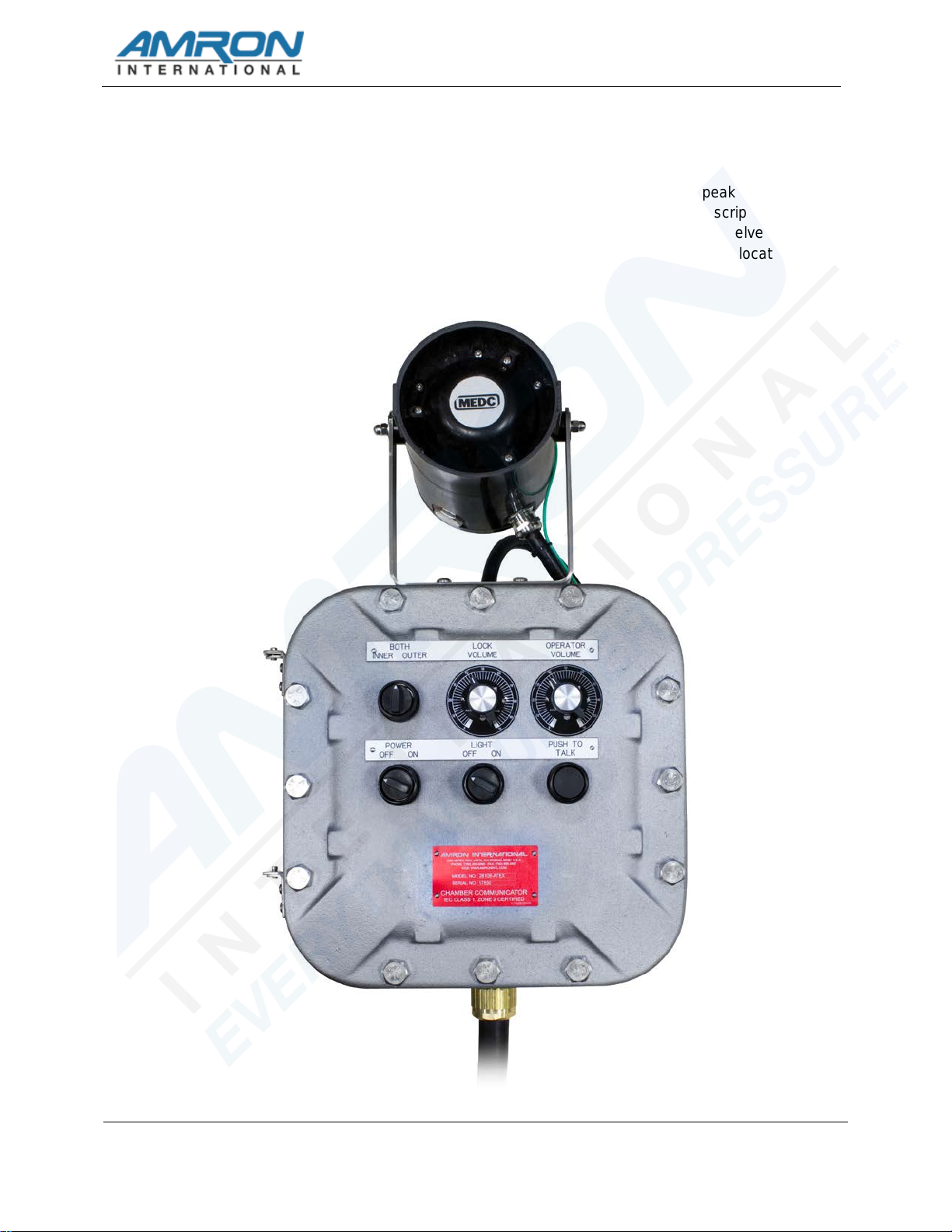
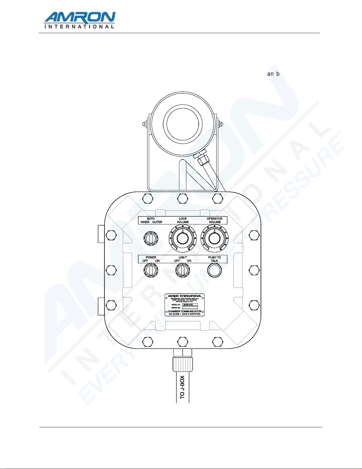
4.1 FRONT PANEL CONTROLS
The following controls and connections are located on the front panel of the 2810E-ATEX.
4.1.1 POWER SWITCH – Turns the power on/off to the communicator. It does not affect
the chamber light power. Turn this control to ON to power the communicator and
OFF to turn the communicator off.
4.1.2 LIGHT SWITCH - This switch allows the operator to turn on and off the chamber
light(s). This control is on a separate circuit from the communicator power and is
not affected by the communicator POWER SWITCH
4.1.3 PUSH-TO-TALK BUTTON - This button allows the operator to talk to the chamber
occupant(s) by talking into the HORN SPEAKER while pushing this button.
4.1.4 LOCK VOLUME - This control sets the volume for the chamber. Rotate this knob
clockwise to increase the volume.
4.1.5 OPERATOR VOLUME - This control sets the volume for the HORN SPEAKER.
Rotate this knob clockwise to increase the volume.
4.1.6 HORN SPEAKER – is a waterproof, ATEX rated speaker that allows the operator
to monitor communication to the chamber and acts as a microphone by using the
PUSH-TO-TALK BUTTON. The volume level is controlled by the OPERATOR
VOLUME.
4.1.7 LOCK SELECTOR SWITCH – This rotary switch is used to select which of the two
locks in the chamber that the operator will communicate with. There are three
positions; INNER, BOTH and OUTER. The INNER and OUTER positions allow to
the operator to monitor and talk to the selected chamber only. With the LOCK
SELECTOR SWITCH in the BOTH position, the operator will monitor and talk to
both chamber locks at the same time.
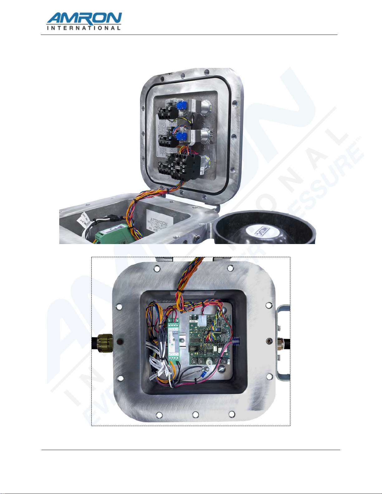
4.2 SYSTEM CONNECTIONS
The 2810E-ATEX system connections are made through the cable location at the bottom of
the enclosure with four twisted wire pairs and an Earth Ground wire.
4.2.1 INPUT POWER – Black & white twisted wire pair. The black wire is connected to
the positive supply terminal and the white wire is connected to the negative supply
terminal. The 2810E-ATEX will accept input voltages from 12 to 24 VDC.
4.2.2 CHAMBER LIGHT – Black & white twisted wire pair. The black wire is connected
to the positive supply terminal and the white wire is connected to the negative
supply terminal. It provides power to the chamber light(s) and is controlled by the
LIGHT SWITCH on the front panel. The current is not limited by communicator
circuitry and the power comes directly from the input power. It is advised that an in-
line fuse holder with the appropriate fuse be installed between the 2810E-ATEX
and the chamber light wiring.
4.2.3 INNER CHAMBER – Black & white twisted wire pair. No polarity is required. It is
connected to the chamber speaker located in the inner lock.
4.2.4 OUTER CHAMBER – Black & white twisted wire pair. No polarity is required. It is
connected to the chamber speaker located in the outer lock.