Amron 2810E-02 User manual

User Manual
For
Amron International, Inc.
Amron Model 2810E-02
Single Lock Chamber Communicator
S/N ____________________
1380 Aspen Way, Vista California 92081-8349
United States of America
Phone: (760) 208-6500
Fax (760) 599-3857
Email: sales@amronintl.com
Web: www.amronintl.com
This manual and the information contained herein are provided for use as an operation and maintenance
guide. No license or rights to manufacture, reproduce, or sell either the manual or articles described
herein are given. Amron International, Inc. reserves the right to change specifications without notice.
Copyright© 2017 Amron International, Inc.


MODEL 2810E-02 USER MANUAL
2810E-02-UM REV 2.0
i
TABLE OF CONTENTS
1. INTRODUCTION AND SPECIFICATIONS...........................................................................................1
INTRODUCTION............................................................................................................................11.1 ELECTRICAL SPECIFICATIONS...................................................................................................11.2 MECHANICAL SPECIFICATIONS.................................................................................................21.3 MODEL 2810E-02 FRONT PANEL.................................................................................................21.4 MODEL 2810E-02 REAR PANEL...................................................................................................31.5 ACCESSORIES..............................................................................................................................31.6
2. CONTROLS AND CONNECTIONS ......................................................................................................6
OPERATOR AND CHAMBER CONTROLS ...................................................................................62.1 CHAMBER CONNECTIONS ..........................................................................................................92.2
3. OPERATION........................................................................................................................................10
CHARGING THE BATTERY.........................................................................................................103.1 INITIAL POWER ON -BATTERY CONDITION CHECK...............................................................103.2 MODES OF OPERATION.............................................................................................................113.3
4. MAINTENANCE ..................................................................................................................................13
CHAMBER COMMUNICATOR CHECK PROCEDURES.............................................................134.1 GENERAL MAINTENANCE .........................................................................................................154.2 TROUBLESHOOTING..................................................................................................................174.3
5. DRAWINGS.........................................................................................................................................20
FRONT PANEL PARTS LOCATOR, MODEL 2810E-02 ..............................................................215.1 MOUNTING DETAIL, MODEL 2810E-02......................................................................................225.2
6. PARTS LIST........................................................................................................................................23
MODEL 2810E-02 TOP ASSEMBLY............................................................................................246.1 2810A-FS FIELD SPARES KIT.....................................................................................................246.2
7. LIMITED WARRANTY AND SERVICE POLICY ................................................................................25

MODEL 2810E-02 USER MANUAL
2810E-02-UM REV 2.0
1
1. INTRODUCTION AND SPECIFICATIONS
INTRODUCTION1.1
The 2810E-02 is the newest member of the Amron International AMCOM series of chamber
communicators. The 2810E-02 is a full featured, panel mounted, single chamber
communicator that uses state-of-the-art electronics and introduces several new features.
The first new feature is a digital audio power amplifier, which significantly reduces the
current draw, nearly doubling the battery life. The 2810E-02 uses a new audio filtering
network for improved sound clarity and communications. An auxiliary audio input allows
chamber occupants to listen to audio from a MP3 player while remaining in constant
communication with the operator. Please note that this feature is only available for a
chamber operating in the 4-Wire mode. These new features allow the AMCOM I 2810E-02 to
remain the most advanced single chamber communicator on the market. To enjoy all the
features, it is important that the operator read and understand the entire manual including all
warnings.
The 2810E-02 can operate in 2-Wire or Full Duplex (4-Wire) communication modes. There is
a single volume control for the up-link (Operator) and another volume control for the down-
link (Chamber). Designed for a long and dependable service life, the 2810E-02 has a
stainless steel front panel with a waterproof speaker and heavy-duty switches with
waterproof seals. The 2810E-02 is enclosed in a rugged, aluminum housing with power and
chamber connections located on the back panel.
ELECTRICAL SPECIFICATIONS1.2
Input Impedance (Microphone Inputs) ..................................................................... 300 Ohms
Frequency Response.......................................................................................... 300 - 4000 Hz
Common Mode Rejection (minimum)................................................................................40 dB
Entertainment Input Impedance ..............................................................................>47 kOhms
Current Drain Maximum Full Volume...........................................................................3 Amps
Typical Quiescent.............................................................................55 mAmps
Minimum Load Impedance............................................................................................ 2 Ohms
AC Supply Voltage.................................................................................90-264 VAC, 50-60 Hz
Nominal Power Supply Voltage......................................................................................12 VDC
Operational Supply Voltage .........................................................................................9-8 VDC
Sensitivity (Input)....................................................................................................... 7.2 mVRMS
Maximum Output Power (4 Ohm Load, 14 VDC).........................................................20 Watts
Battery Life (typical)..................................................................................................... 85 Hours

MODEL 2810E-02 USER MANUAL
2810E-02-UM REV 2.0
2
MECHANICAL SPECIFICATIONS1.3
Panel ........................................................................................Powder Coated Stainless Steel
Enclosure ....................................................................................... Black Anodized Aluminum
Height..............................................................................................................6.75 in. (17.2cm)
Width.............................................................................................................10.75 in. (27.3cm)
Chassis Clearance Depth .................................................................................7.0 in. (17.7cm)
Weight With Batteries
2810E-02.........................................................................................................11.5 Lbs. (5.2kg)
MODEL 2810E-02 FRONT PANEL1.4
All of the controls for the Model 2810E-02 are located on the front panel including the
connectors for the operator handheld microphone or headset, tape recorder and auxiliary
audio input. The 2810E-02 comes with the Amron Model 2405-28 PUSH-TO-TALK handheld
microphone.
The 2810E-02 can be used in a stand-alone application or panel mounted. Four holes,
located on the front panel, allow the unit to be securely mounted for a clean, professional
look.

MODEL 2810E-02 USER MANUAL
2810E-02-UM REV 2.0
3
MODEL 2810E-02 REAR PANEL1.5
The AC power cord and the chamber connectors are located on the rear panel of the 2810E-
02. The Model 2810E-02 comes equipped with a sealed lead-acid rechargeable battery and
an internal universal input (115/230 VAC) battery charger. The battery charger has medical
grade electrical isolation for maximum safety to the chamber occupants.
ACCESSORIES1.6
Amron produces a series of accessories designed to operate with the entire line of AMCOM
diving communicators.
1.6.1 Amron Heavy-Duty Headset - Model 2401-28
The Model 2401-28 is a heavy-duty headset with boom microphone. It comes
equipped with color-coded, dual banana plugs that mate directly to AMCOM
chamber communicators. It includes a six-foot (1.8 meter) cord.
1.6.2 Amron Standard Headset - Model 2460-28
The Model 2460-28 is a light and comfortable headset designed for extended wear
at an economical price. It comes equipped with color-coded, dual banana plugs
that mate directly to AMCOM chamber communicators as well as a spiral cord that
can be extended up to 8 feet (2.4 meters).
1.6.3 Amron Push-to-Talk Microphone - Model 2405-28
The Model 2405-28 is a hand-held, noise canceling, push-to-talk microphone that
provides excellent sound quality to the chamber. It comes equipped with a spiral
cord that can be extended up to 6 feet (1.8 meters).

MODEL 2810E-02 USER MANUAL
2810E-02-UM REV 2.0
4
1.6.4 Amron Remote Walk-and-Talk Module - Model 2822-28
Designed for Full Duplex (4-Wire) applications, the Model 2822-28 provides the
operator with mobility around the chamber room while maintaining communications
with the chamber. It comes equipped with a small clip-on belt module that contains
the connectors for the headset, and 25 feet (7.6 meters) of lightweight flexible
cable. Custom cable lengths are available.
1.6.5 Amron Remote Push-to-Talk Module - Model 2821-28
Designed for 2-Wire applications, the Model 2821-28 provides the operator with
mobility around the chamber room while maintaining communications with the
chamber. It comes equipped with a small clip-on belt module that contains a Push-
to-Talk switch, connector for the headset, and 25 feet (7.6 meters) of lightweight
flexible cable. Custom cable lengths are available.
1.6.6 Audio Adaptor Cable - Amron Part Number 180-1000-00
A 2 meter long cable with two RCA Phono plugs that connect the auxiliary audio
input to a standard 3.5 mm stereo phone plug which mates to the headphone jack
of most common portable audio devices.
1.6.7 Amron Standard Headset - Model 2460-31R
This light and comfortable headset is designed for extended wear by chamber
occupants. The Model 2460-31R features an adjustable boom microphone, vinyl
cushioned adjustable ear pads and a spiral cord that can be extended up to 8 feet
(2.4 meters). It can be plugged into the headset jacks of most models of Amron
Chamber Speakers.
1.6.8 Amron Chamber Speaker - Model 3110
The Model 3110 Chamber Speaker includes a push-to-talk switch along with a
headset connector. The speaker provides the occupants the ability to listen to
audio entertainment either via the speaker or headset. When the occupants want
to talk to the operator, the push-to-talk switch on the chamber speaker must be
pressed even if the headset is in use.
1.6.9 Amron Chamber Speaker - Model 3115
The Model 3115 Chamber Speaker allows the operator to monitor conversations
within the chamber with the speaker wired in 2-WIRE mode. There is a speaker
on/off switch that allows occupants to turn off the speaker for private
conversations. The operator can talk to the occupants by using the PUSH-TO-
TALK BUTTON or PUSH-TO-TALK JACK. The Model 3115 also features a
headset jack wired in Full-Duplex (4-Wire) mode that allows an occupant to enjoy
audio entertainment by using the Model 2460-31R headset along with talking to
the chamber operator without the use of the PUSH-TO-TALK BUTTON or PUSH-
TO-TALK JACK. This speaker is approved for US Navy chambers.

MODEL 2810E-02 USER MANUAL
2810E-02-UM REV 2.0
5
1.6.10 Amron Chamber Speaker - Model 3113
The Model 3113 Chamber Speaker has all the features of the Model 3115 except
for the speaker on/off switch.
1.6.11 Amron Inner-Lock Combo Box - Model 3125
The Model 3125 features a talk-back speaker with on/off switch and headset jack
that operates in the same manner as the Model 3115. It also includes a sound-
powered phone with bracket, chamber temperature probe, scrubber power circuit
wiring, chamber environmental conditioning unit wiring and electrical penetrator
adaptor all together in a single pre-wired, pre-tested housing.
1.6.12 Amron Outer-Lock Combo Box - Model 3126
The Model 3126 features a talk-back speaker with on/off switch and headset jack
that operates in the same manner as the Model 3115. It also includes the sound-
powered phone and bracket like the Model 3125 but does not have the additional
chamber function wiring of the 3125.

MODEL 2810E-02 USER MANUAL
2810E-02-UM REV 2.0
6
2. CONTROLS AND CONNECTIONS
Before using the 2810E-02 chamber communicator, the operator should be familiar with all the
controls and connections. While reading this manual, you will find capitalized words such as PANEL
SPEAKER. These words are to remind the reader that additional information can be found in this
section of the manual.
OPERATOR AND CHAMBER CONTROLS2.1
The following controls are located on the front panel of the 2810E-02
2.1.1 POWER SWITCH - The power on/off control.
2.1.2 SPEAKER SWITCH - This switch allows the operator to turn off the speaker. If the
operator is using a headset, it may be necessary to turn off the speaker in order to
prevent acoustic feedback.
2.1.3 PUSH-TO-TALK BUTTON - This button allows the operator to talk to the chamber
when operating in the 2-Wire mode. It is not necessary to use this control in the Full
Duplex (4-Wire) mode. When using Full Duplex mode, this control allows the
operator to interrupt the chamber by forcing the chamber into listen only mode.
2.1.4 CHAMBER VOLUME - This control sets the volume for the chamber's earphone
including any signal from the AUXILIARY AUDIO INPUT. Rotate this knob clockwise
to increase the volume.
2.1.5 OPERATOR VOLUME - This control sets the volume for the operator's earphone
and/or panel speaker. Rotate this knob clockwise to increase the volume.

MODEL 2810E-02 USER MANUAL
2810E-02-UM REV 2.0
7
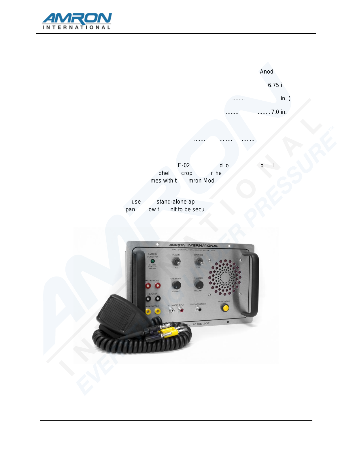
2.1.6 PANEL SPEAKER - A waterproof, acoustic speaker that allows the operator to listen
to the chamber occupants and acts as a microphone by using the PUSH-TO-TALK
BUTTON. The volume level is controlled by the CHAMBER TO OPERATOR
VOLUME control and it can be turned off using the SPEAKER SWITCH.
2.1.7 BATTERY CONDITION INDICATOR - This LED is used by the operator to
determine the available battery level. A steady green light means that the battery
charge level is greater than 30%. When the battery reaches approximately 30%
remaining life, the LED will start blinking at a rate of about once per second. When
the battery reaches its end-of-charge, the LED will turn off and the 2810E-02 will go
into shutdown mode to prevent damaging the communicator or rechargeable
battery. It is advised that the 2810E-02 be connected to an AC outlet as soon as
possible once the BATTERY CONDITION INDICATOR starts blinking. While there
should be enough time to safely complete a normal diving operation, the exact
amount of time is dependent on the age and condition of the sealed lead acid
battery.
2.1.8 OPERATOR HEADSET - This is the dual banana jack (color-coded black) that
functions as both an output (earphone) and input (microphone) for the operator as
controlled by the PUSH-TO-TALK BUTTON and PUSH-TO-TALK JACK. Using this
connection, the operator can be wired in either 2-Wire or Full Duplex (4-Wire) mode
regardless of the mode used for the chamber.
To connect the operator in the Full Duplex (4-Wire) mode, connect the earphone
(black) banana plug of the headset to this jack and the microphone (red) to the
OPERATOR MICROPHONE jack (red). In this mode, the operator does not have
to use the PUSH-TO-TALK BUTTON to communicate with a chamber occupant
who is also operating in the Full Duplex (4-Wire) mode. This configuration can be
used even if the chamber is wired in 2-Wire mode. In that situation, the operator is
required to use the PUSH-TO-TALK BUTTON or PUSH-TO-TALK JACK.
The headset microphone is always active which means that there can be acoustic
feedback between the PANEL SPEAKER and the microphone if the operator is
near the 2810E-02. To prevent this, the PANEL SPEAKER can be turned off using
the SPEAKER SWITCH. Another option is to move the operator away from the
2810E-02 by using the Amron Model 2822-28 Walk-and-Talk Module accessory.
This allows the operator to communicate while other members of the chamber
operations crew listen using the PANEL SPEAKER. This module comes with 25
feet (7.6 meters) of cable (custom cable lengths are available).
The operator can also be connected in 2-Wire mode by stacking both the
earphone (black) and microphone (red) banana plugs into the OPERATOR
HEADSET jack (black). The chamber does not have to be connected in 2-Wire
mode if the operator is in 2-Wire mode. In order to talk to occupants, the operator
must use either the PUSH-TO-TALK BUTTON or PUSH-TO-TALK JACK. Since
the headset microphone is not active until one of the push-to-talk methods is used,
there is no chance for acoustic feedback to occur and surface conversation or
noise is not transmitted to the chamber and the PANEL SPEAKER can be left on.
This may, for some situations, make for a better overall communication
experience. If the operator requires more mobility, the Amron Model 2821-28

MODEL 2810E-02 USER MANUAL
2810E-02-UM REV 2.0
8
Remote Push-to-Talk Module can be used to extend the headset cable. It includes
a push-to-talk button on a clip-on belt module and comes standard with 25 feet
(7.6 meters) of cable (custom cable lengths are available).
The operator may also use the included Amron Model 2405-28 Push-to-Talk
Microphone. This microphone comes with two color-coded banana plugs. The
black plug goes into the OPERATOR HEADSET jack and the yellow plug goes in
the PUSH-TO-TALK JACK. To communicate with the chamber, the operator
presses the button on the side of the microphone. There is no chance of acoustic
feedback since the PANEL SPEAKER is cut-off when the operator uses the
microphone. When using the Push-to-Talk Microphone, the SPEAKER SWITCH
must be turned on in order to hear the occupants.
2.1.9 OPERATOR MICROPHONE - This is a dual banana jack (color-coded red) that
functions as the microphone input from the operator's headset. It is only used if the
operator is in Full Duplex (4-Wire) mode.
2.1.10 PUSH-TO-TALK JACK - This is a dual banana jack (color-coded yellow) that allows
for remote keying of the push-to-talk function of the 2810E-02. The difference
between using the PUSH-TO-TALK JACK and PUSH-TO-TALK BUTTON is that the
button allows the operator to communicate using the PANEL SPEAKER as a
microphone. If both are used at the same time, the PANEL SPEAKER is active as a
microphone. This allows another operation crew member to talk to the occupants
using the PANEL SPEAKER even if the operator is away from the 2810E-02 using
the Remote Push-to-Talk Module in 2-Wire mode.
2.1.11 RECORDER OUTPUT - This is a single RCA Phono jack (color-coded black) that
provides a transformer isolated output of both operator and occupant
communications. It is designed to drive the standard line-level inputs of audio or
video recorders with input impedances as low as 600 Ohms. The RECORDER
OUTPUT will not record the signal from the AUXILIARY AUDIO INPUT.
2.1.12 AUXILIARY AUDIO INPUT - This is a set of two RCA Phone jacks (color-coded red
and white) that provides a means to connect an external audio signal for occupant
entertainment. Although this input will accept a stereo audio source, it will be
converted into a monaural signal before going to the chamber. This signal is not
heard in either the operator headset or the PANEL SPEAKER. The earphone output
of most MP3 players can be connected to this input using an adaptor cable like the
Amron Audio Adaptor Cable (Amron Part Number 180-1000-00). This feature will
only work if the chamber is wired in Full Duplex (4-Wire) mode.
There is no separate volume control provided for the AUXILIARY AUDIO INPUT.
The audio device provides the volume control. It is advised at the start of chamber
operations, and before the external audio device is turned on, that the operator
adjust and verify the CHAMBER VOLUME level is correct and comfortable for
occupants. Then starting with the lowest volume, adjust the volume on external
devices until a comfortable level is achieved. If the operator is connected in the Full
Duplex (4-Wire) mode, the volume level should not be so loud as to prevent
occupants from hearing the operator. If the operator is connected in the 2-Wire
mode, then the entertainment will be cut off whenever the PUSH-TO-TALK

MODEL 2810E-02 USER MANUAL
2810E-02-UM REV 2.0
9
BUTTON or PUSH-TO-TALK JACK is used. The PUSH-TO-TALK BUTTON can be
used by the operator to cut off the entertainment even if the operator is connected in
the Full Duplex (4-Wire) mode.
WARNING!
The AUXILIARY AUDIO INPUT is not electrically isolated from the circuitry of the 2810E-02. Any external
equipment connected to the input should not be AC powered or connected to the AC mains indirectly
through any equipment without the proper isolation. Failure to follow this warning may result in
electrocution or death.
WARNING!
To ensure clear communications when using the AUXILIARY AUDIO INPUT, it is critical that the volume
level of the external audio device be set at a level below that of the operator's microphone as described
above. It is recommended that the operator use the PUSH-TO-TALK BUTTON when talking to the
occupant(s) as this cuts off the signal from the AUXILIARY AUDIO INPUT.
CHAMBER CONNECTIONS2.2
The chamber connections are located on the rear left side of the communicator.
CHAMBER MICROPHONE - This is a dual banana jack (color-coded red) that functions as
both an output (earphone) and input (microphone) for the chamber occupants as controlled
by the PUSH-TO-TALK BUTTON and PUSH-TO-TALK JACK. Using this connection, the
chamber can be wired in either 2-Wire or Full Duplex (4-Wire) mode regardless of the mode
used for the operator.
2.2.1 Full Duplex (4-Wire) Mode
Connect the chamber microphone red banana plug (AUDIO UPLINK) to the red
jack located on rear side of chassis and the chamber earphone black banana plug
(AUDIO DOWNLINK) to the black jack located on rear side of chassis. Occupants
can use this mode even if the operator is wired in 2-Wire mode, for example, to
take advantage of the audio entertainment feature of the 2810E-02.
2.2.2 2-Wire Mode
Double stack the chamber microphone (red banana plug) and the earphone (black
banana plug) to the red jack located on the rear side of chassis. If occupants are
using a headset, connect both the headset microphone and earphone to this jack.
In this mode, the chamber speaker will act as a microphone and be heard on
operator’s headset and/or PANEL SPEAKER unless the PUSH-TO-TALK
BUTTON or PUSH-TO-TALK JACK is activated.
2.2.3 CHAMBER EARPHONE - This is a dual banana jack (color-coded black) that
functions as the output for chamber occupant’s earphone. It is only used when the
chamber is in Full Duplex (4-Wire) mode.

MODEL 2810E-02 USER MANUAL
2810E-02-UM REV 2.0
10
3. OPERATION
The 2810E-02 is a panel mounted chamber communication system designed to provide reliable
voice communications between the chamber operator and occupants.
CHARGING THE BATTERY3.1
The Model 2810E-02 is supplied with an internal sealed lead acid battery. To charge the
battery, connect the AC power cord located on the back panel to an AC outlet. The internal
battery charger operates form 90-264 VAC, 50-60 Hz without the user having to make any
adjustments.
The 2810E-02 internal battery charger is designed to charge the battery in float mode so the
charger can be left on indefinitely, without damage, to ensure the battery is fully charged and
the unit is ready to use. A fully discharged battery will take approximately 10 hours to reach
full charge (depending of the age of the battery and the surrounding temperature). To ensure
maximum service life, the battery should be fully charged at least once every six months.
The operating time for a fully charged battery is approximately 85 hours. The exact operating
time depends on the age of the battery and the ambient temperature. The sealed lead acid
battery used in the 2810E-02 has a service life of 300 full charge/discharge cycles or 3
years. The BATTERY CONDITION INDICATOR will start to blink when the battery has
approximately 30% remaining charge. To maximize the service life, the battery should be
recharged as soon as possible after the indicator starts to blink. When the battery reaches
the full discharge state, the 2810E-02 will shut down to prevent damage to both the battery
and the electronics.
INITIAL POWER ON - BATTERY CONDITION CHECK3.2
Turn all the volume controls to minimum and turn on the POWER SWITCH. The state of the
battery is shown on the BATTERY CONDITION INDICATOR as follows:
•STEADY GREEN - the battery is good and has more than 30% remaining life
•BLINKING GREEN - the battery is low and has less than 30% remaining life
The BLINKING GREEN light provides a warning that the battery is low and should be
changed or recharged before starting chamber operations. When the indicator starts
BLINKING GREEN during operation, it means that there is, depending on age of the battery
and the ambient temperature, approximately 24 hours of remaining life. This should be
sufficient time to safely complete chamber operations or to connect the 2810E-02 to an AC
power source. A battery that has not been used for a long period of time will exhibit a higher
voltage than the actual charge state. This is known as surface charge and will quickly
dissipate once the unit is turned on. It is recommended that the unit be left on for 5 minutes
before relying on the BATTERY CONDITION INDICATOR.

MODEL 2810E-02 USER MANUAL
2810E-02-UM REV 2.0
11
WARNING!
Surges and spikes are common on AC lines found onboard ships, from local generators, or at the end of
a long extension lines. These spikes can exceed 1kV! Such spikes can be high enough to cause the
input fuses on the 2810E-02 internal battery charger to blow and, in extreme cases, actually damage the
charger circuitry. Amron has designed this battery charger to isolate such faults to ensure that they will
not cause a safety issue for the operator or chamber occupants. Amron strongly recommends that the
2810E-02 be operated on AC circuits protected by a Ground Fault Circuit Interrupters (GFCI) for
additional safety.
MODES OF OPERATION3.3
The 2810E-02 has the ability to operate in either 2-Wire or Full Duplex (4-Wire). Both the
operator and chamber occupants can be connected in either mode or a combination of
modes can be used. For example, the chamber can be connected in Full Duplex (4-Wire)
mode to take advantage of the new entertainment feature while the operator is wired in 2-
Wire mode. If either the operator or the chamber is wired in 2-Wire mode, the operator must
use a push-to-talk, either the PUSH-TO-TALK BUTTON or PUSH-TO-TALK JACK, when
talking to chamber occupants.
2-Wire communication is defined as a single communication path; normally a chamber
occupant is the priority signal path, the operator listens to the occupants. Signal reversing is
accomplished by pushing the PUSH-TO-TALK BUTTON, the occupant hears the operator.
Often times a 4-conductor communication cable is used with 2 wires tied together as a pair
for redundancy, this is still a 2-Wire system. Since only one person can talk at a time, there
is a level of discipline that goes with using 2-Wire mode in order to obtain clear
communication. One advantage of 2-Wire is that the operator's microphone is not active
unless one of the two push-to-talk controls, PUSH-TO-TALK BUTTON or PUSH-TO-TALK
JACK, are active. This eliminates any possible acoustic feedback between the operator's
microphone and the PANEL SPEAKER. It also prevents noise from the outside reaching
chamber occupants and allows the operator to communicate with other members of the
chamber operations crew without involving occupants. If the chamber is connected in 2-Wire
mode, the AUDIO AUXILIARY INPUT cannot be used to deliver entertainment to the
occupants.
Full Duplex (4-Wire) communication is defined as a dual communication path, a signal path
(a pair of wires) for up-link and a signal path (a pair of wires) for down link. A common
example of Full Duplex communication is the telephone. Full Duplex (4-Wire) has the
advantage of natural communication without having to use the PUSH-TO-TALK BUTTON.
This keeps the operator's hands free to perform other task. It does not require the same
level of discipline to achieve clear communications that 2-Wire does. It has the advantage
that neither a chamber occupant nor the operator is cut off when the other is talking.
Because the chamber microphone is not connected in parallel with the chamber earphone,
the occupant is louder and potentially clearer in Full Duplex (4-Wire) mode.

MODEL 2810E-02 USER MANUAL
2810E-02-UM REV 2.0
12
3.3.1 2-WIRE
Turn power switch to ON, turn speaker switch to ON, and adjust both volume
controls to mid-scale. The operator has to depress PUSH-TO-TALK BUTTON in
order to talk to chamber occupants. Operator and occupants talk to each other
while the operator adjusts the volume controls as below:
OPERATOR VOLUME
While chamber occupant is talking, the operator adjusts this volume control to a
comfortable hearing level.
CHAMBER VOLUME
While operator depresses the appropriate PTT switch and talks into the panel
speaker, headset microphone or handheld microphone, the operator adjusts the
volume control to a comfortable hearing level for the occupant.
3.3.2 FULL DUPLEX (4-WIRE)
Turn power switch to ON; turn speaker switch to OFF; adjust both volume controls
to mid-scale. Operator and occupants use headsets and talk to each other while
the operator adjusts the volume controls as below:
OPERATOR VOLUME
While chamber occupant is talking, the operator adjusts this volume control to a
comfortable hearing level.
CHAMBER VOLUME
While operator is talking, the operator adjusts this volume control to a comfortable
level for the chamber occupants. If the AUXILIARY AUDIO INPUT will be used, the
volume level of the external audio device should not be higher than the operator’s
voice.
WARNING!
To ensure clear communications when using the AUXILIARY AUDIO INPUT, it is critical that the volume
level of the external audio device be set at a level below that of the operator's microphone as described
above. It is recommended that the operator use the PUSH-TO-TALK BUTTON when talking to the
chamber occupant(s) as this cuts off the signal from the AUXILIARY AUDIO INPUT.

MODEL 2810E-02 USER MANUAL
2810E-02-UM REV 2.0
13
4. MAINTENANCE
The following section describes the procedures for checking the operation of your 2810E-02
chamber communicator, general maintenance procedures, and how to troubleshoot common
problems.
CHAMBER COMMUNICATOR CHECK PROCEDURES4.1
The following are a series of step-by-step procedures to perform a functional check of your
2810E-02 communicator using only a headset. These steps check all communication
functions of the 2810E-02 in both 2-Wire and Full Duplex (4-Wire) mode. If the
communicator checks out using these procedures, then any communication problems are
probably located somewhere else in the system setup.
4.1.1 FULL DUPLEX (4-WIRE) CHECK
This procedure checks the communicator functions in the Full Duplex (4-Wire)
mode.
1. Set all volume controls to the mid-scale (halfway) position.
2. Turn the SPEAKER SWITCH off to avoid acoustic feedback.
3. Turn on the communicator and verify the BATTERY CONDITION
INDICATOR is on or blinking. If the LED does not come on at all, then replace
or recharge the battery. If that does not resolve the problem, then go to the
troubleshooting section to determine the cause.
4. Identify the microphone and headset leads. When using an Amron headset,
the microphone is the red banana plug and the headset is the black banana
plug.
5. Plug the microphone lead into the OPERATOR MICROPHONE (red) jack and
the headset lead into the OPERATOR HEADSET (black) jack.
6. Don the headset and talk into the microphone. You should be able to hear
yourself in the headset. Adjust the OPERATOR VOLUME control and verify
the level can be adjusted to a comfortable level.
7. Move the headset microphone lead to the CHAMBER MICROPHONE (red)
jack. Talk into the microphone. You should be able to hear yourself in the
headset. Adjust the OPERATOR VOLUME control and verify that the level
can be adjusted to a comfortable level.
8. Move the headset lead to the CHAMBER EARPHONE (black) jack. Talk into
the microphone. You should be able to hear yourself in the headset. Adjust
the CHAMBER VOLUME control and verify that the level can be adjusted to a
comfortable level.
9. Connect a source device, such as a MP3 player, to the AUXILIARY AUDIO
INPUT. Set the volume control of the device to low and start playing music.
The music should be heard in the headset. Adjust the volume as required.

MODEL 2810E-02 USER MANUAL
2810E-02-UM REV 2.0
14
Verify that the music is cut off when the PUSH-TO-TALK BUTTON is
pressed.
This completes the check of the Full Duplex (4-Wire) function of the communicator.
If at any point in the test you were not able to hear yourself in the headset as
indicated by the test, refer to the troubleshooting section to determine the cause.
4.1.2 2-WIRE CHECK
This procedure checks the communicator functions in the 2-Wire mode.
1. Set all the volume controls to the mid-scale (halfway) position.
2. Turn the SPEAKER SWITCH off to avoid acoustic feedback.
3. Turn on the communicator and verify the BATTERY CONDITION
INDICATOR is on or blinking. If the LED does not come on at all, then replace
or recharge the battery. If that does not resolve the problem, then go to the
troubleshooting section to determine the cause.
4. Identify the microphone and headset leads. When using an Amron headset,
the microphone is the red banana plug and the headset is the black banana
plug.
5. Plug the microphone lead into the OPERATOR HEADSET (black) jack and
the headset lead into the CHAMBER MICROPHONE (red) jack.
6. Don the headset. Talk into the microphone while pressing the PUSH-TO-
TALK BUTTON. You should be able to hear yourself in the headset. Adjust
the CHAMBER VOLUME control and verify that the level can be adjusted to a
comfortable level.
7. Unplug the microphone lead. Turn on the SPEAKER SWITCH. Press the
PUSH-TO-TALK BUTTON while speaking into the PANEL SPEAKER. You
should be able to hear yourself in the headset. Adjust the CHAMBER
VOLUME if necessary and verify that the level can be adjusted to a
comfortable level.
8. Plug the microphone lead into the OPERATOR HEADSET (black) jack. Short
the PUSH-TO-TALK JACK (yellow) with a short piece of wire. Talk into the
microphone and verify that you hear yourself in the headset. Remove the
short. Turn off the SPEAKER SWITCH.
9. Move the microphone lead to the CHAMBER MICROPHONE (red) jack and
move the headset lead to the OPERATOR HEADSET jack.
10. Talk into the microphone and verify you can hear yourself in the headset. The
PUSH-TO-TALK BUTTON should not be pressed. Adjust the OPERATOR
VOLUME control and verify that the level can be adjusted to a comfortable
level.

MODEL 2810E-02 USER MANUAL
2810E-02-UM REV 2.0
15
GENERAL MAINTENANCE4.2
The 2810E-02 chamber communicator is designed to provide years of continuous, failure-
free service when properly used and maintained. There are a few important things that the
user can do to extend the life of their equipment
1. Handle the chamber communicator with care. If not panel mounted, do not throw it
around or drop it. Select a work area where the communicator and wires connecting to
it are out of everyone's way so it does not get knocked over.
2. The 2810E-02 rechargeable battery should be recharged after use or as soon as
possible when the BATTERY CONDITION INDICATOR starts blinking.
4.2.1 BATTERY REPLACEMENT
1. Remove all AC power.
2. Turn off unit.
3. Disconnect all cables.
4. Remove 4 ea. pan head Phillips screws: 2 ea. on each side of "AMRON
INTERNATIONAL" & 2 ea. on each side of "MODEL 2810E-02".
5. Lift the 2810E-02 out of chamber control panel.
6. Remove 4ea. 8-32x1/2 pan head Phillips screws: 2ea. from both sides of
radio chassis.
7. Tilt front panel to side of chassis.
8. Remove 2 ea. screws from side of chassis that secures battery bracket.
9. Disconnect the two slide terminals from battery.
10. Lift out battery.
11. Replace with new battery.
12. Connect the two slide terminals to battery, RED wire to Positive, BLACK wire
to Negative.
13. Re-install battery bracket and 2 ea. screws.
14. Permanently tighten screws.
15. Place panel on top of chassis, being careful not to pinch or damage any
wires.
16. Install 4 ea. screws on side of chassis and tighten.
17. Install communicator into cutout on chamber control panel.
18. Install and tighten 4 ea. screws to secure radio to chamber control panel.

MODEL 2810E-02 USER MANUAL
2810E-02-UM REV 2.0
16
19. Perform Power On - Battery Check
20. Plug 2810E-02 into AC power and allow battery to charge for 4 hours
(depending of the age of the battery and the surrounding temperature).
4.2.2 RECOMMENDED MAINTENANCE SCHEDULE
The following sections outline the recommended scheduled maintenance for the
2810E-02.
1. DAILY MAINTENANCE - Wipe off any accumulated dust or dirt on the front
panel or connectors using a clean, damp cloth. Pay particular attention to
where the various front panel components attach to the panel. Inspect the
outer case for any damage.
2. WEEKLY MAINTENANCE - Wipe off any accumulated dust or dirt on the front
panel or connectors using a clean, damp cloth. Pay particular attention to
where the various front panel components attach to the panel.
3. 6 MONTH CHECK - Wipe off any accumulated dust or dirt on the front panel
or connectors using a clean, damp cloth. Pay particular attention to where the
various front panel components attach to the panel. Inspect the outer case for
any damage.
Inspect the PUSH-TO-TALK BUTTON, toggle switches and volume
controls for smooth operation.
Perform the 2-Wire and Full Duplex (4-Wire) system checks as described
in section 5.1.
4.2.3 YEARLY CHECK
For maximum service life, it is recommended that the chamber communicator be
sent back to Amron for a yearly check.
4.2.4 LONG TERM STORAGE
If the chamber communicator is to be stored for a period greater than 30 days, it is
recommended that it be stored in a cool dry location. Make sure that the POWER
SWITCH is turned off during storage. The 2810E-02 should be stored plugged into
an AC outlet to ensure that the communicator will be fully charged and ready to
use when needed.

MODEL 2810E-02 USER MANUAL
2810E-02-UM REV 2.0
17
TROUBLESHOOTING4.3
The following section will describe the troubleshooting procedure for several common
issues. If these sections do not cover your particular issue, it is recommended that the
chamber wiring be disconnected from the communicator and the check-out procedures in
section 5.1 be conducted. If the chamber communicator passes the check-out procedures
then the issue is most likely in the chamber wiring.
4.3.1 LOW-BATTERY INDICATION
The BATTERY CONDITION INDICATOR indicates the battery level or state-of-
charge by monitoring the battery voltage. The voltage has to be 9 Volts or greater
for the 2810E-02 communicator to operate. If the BATTERY CONDITION
INDICATOR indicates a low (blinking LED) or bad (off LED) after charging, then
either the battery is bad and needs to be replaced or the charger has
malfunctioned.
Before replacing either battery, the battery connections should be checked by
opening the battery compartment and inspecting the wires. Verify that the wires
are firmly attached and that the RED wire is connected to the positive terminal and
that the BLACK wire is connected to the negative terminal.
4.3.2 UNIT NOT OPERATING
The most common reason that a chamber communicator appears to be dead when
the POWER SWITCH and SPEAKER SWITCH are turned on, is a bad or loose
battery. Check the battery per section 5.3.1. If the battery is good, then disconnect
any chamber wiring and perform the communicator check out procedure per
section 5.1.
If the battery and battery connections appear good and the communicator fails the
check-out procedure, then remove the screws holding the front panel. Lift the front
panel up carefully as the panel components are connected to a Printed Circuit
Assembly (PCA) by a wire harness. Verify that the connectors on the PCA are
firmly seated. Check that the wire harnesses are soldered to the various
connectors, controls, and speaker. There should be no loose wires in the system.
Remove the fuse from the PCA. It is marked FH1 and is a cylindrical component.
Verify that the fuse is good by checking the continuity with a multi-meter. If the fuse
is open, replace with a same type: 3.15 Amp, 250V, Fast Acting. Close the front
panel; re-install the screws and re-test the communicator. If the communicator still
appears dead, contact Amron per section 2.2 for further assistance.
4.3.3 LOW VOLUME
Check the volume control settings and adjust if necessary. Check the chamber
connections and verify that the chamber and operator are connected as intended.
Verify the wires and connectors are clean and tight. Check the BATTERY
CONDITION INDICATOR and test the battery if necessary. If the problem persists,
disconnect the chamber wiring and perform the communicator check out
procedure per section 5.1. If the communicator fails the check-out procedure,
contact Amron per section 2.2 for further assistance.
Table of contents
Other Amron Cell Phone manuals

Amron
Amron 2830A/24 Series User manual

Amron
Amron 2820A User manual

Amron
Amron 2810E-ATEX User manual

Amron
Amron 2820A User manual

Amron
Amron 2810A-2001 User manual

Amron
Amron 2830R/24 Series User manual

Amron
Amron 2820A-4003 User manual

Amron
Amron 2825A User manual

Amron
Amron 2830A Series User manual

Amron
Amron AMCOM III series User manual