Amron 2810E User manual

User Manual
for
Amron International, Inc.
Amron Model 2810E and 2810E-1
1-Diver Communicator
S/N______________________
1380 Aspen Way, Vista California 92081-8349
United States of America
Phone: (760) 208-6500
Fax (760) 599-3857
email: sales@amronintl.com
web: www.amronintl.com
This manual and the information contained herein are provided for use as an operation and
maintenance guide. No license or rights to manufacture, reproduce, or sell either the manual or
articles described herein are given. Amron International, Inc. reserves the right to change
specifications without notice.
Copyright© 2013 Amron International, Inc.


MODEL 2810E USER MANUAL
2810E UM REV 7.0
i
TABLE OF CONTENTS
1. INTRODUCTION AND SPECIFICATIONS...........................................................................................1
INTRODUCTION............................................................................................................................11.1 ELECTRICAL SPECIFICATIONS...................................................................................................11.2 MECHANICAL SPECIFICATIONS.................................................................................................21.3 MODEL 2810E WITH BATTERY CHARGER .................................................................................21.4 MODEL 2810E-1.............................................................................................................................31.5
2. WARRANTY AND SERVICE POLICY..................................................................................................4
LIMITEDWARRANTY....................................................................................................................42.1 SERVICE POLICY..........................................................................................................................42.2
3. ACCESSORIES.....................................................................................................................................5
AMRON HEAVY-DUTY HEADSET - MODEL 2401-28..................................................................53.1 AMRON STANDARD HEADSET - MODEL 2460-28.....................................................................53.2 AMRON PUSH-TO-TALK MICROPHONE - MODEL 2405-28 ......................................................53.3 AMRON REMOTE WALK-AND-TALK MODULE - MODEL 2822-28.............................................53.4 AMRON REMOTE PUSH-TO-TALK MODULE - MODEL 2821-28 ...............................................53.5 AUDIO ADAPTOR CABLE - AMRON PART NUMBER 180-1000-00 ...........................................53.6
4. CONTROLS AND CONNECTIONS ......................................................................................................6
TENDER AND DIVER CONTROLS................................................................................................64.1 TENDER CONNECTIONS .............................................................................................................74.2 DIVER CONNECTIONS .................................................................................................................94.3 REAR PANEL CONNECTIONS....................................................................................................104.4 DRAWING, 2-WIRE CONNECTIONS ..........................................................................................124.5 DRAWING, FULL DUPLEX (4-WIRE) CONNECTIONS...............................................................134.6 DRAWING, PUSH-TO-TALK MICROPHONE CONNECTIONS...................................................144.7
5. OPERATION........................................................................................................................................15
CHARGING THE BATTERY (2810E ONLY) ................................................................................155.1 INITIAL POWER ON -BATTERY CONDITION CHECK...............................................................15
5.2 OPERATING ON AC POWER......................................................................................................165.3 MODES OF OPERATION.............................................................................................................165.4
6. MAINTENANCE and troubleshooting ..............................................................................................20
DIVER RADIO COMMUNICATOR CHECK PROCEDURES........................................................206.1 GENERAL MAINTENANCE .........................................................................................................226.2 TROUBLESHOOTING..................................................................................................................236.3
7. FULL DUPLEX (4-WIRE) - WHAT, WHY AND HOW.........................................................................27
WHAT ARE 2-WIRE AND 4-WIRE MODES? ...............................................................................277.1 WHAT IS FULL DUPLEX (4-WIRE)?............................................................................................287.2 WHY FULL DUPLEX (4-WIRE)?...................................................................................................297.3 HOW DO YOU USE FULL DUPLEX (4-WIRE).............................................................................307.4

MODEL 2810E USER MANUAL
2810E UM REV 7.0
ii
8. DRAWINGS.........................................................................................................................................32
FRONT PANEL PARTS LOCATOR, MODELS 2810E &2810E-1 ...............................................338.1 CASE PARTS LOCATOR, MODELS 2810E &2810E-1...............................................................348.2
9. PARTS LIST GENERAL .....................................................................................................................35
MODEL 2810E TOP ASSEMBLY.................................................................................................369.1 MODEL 2810E-1 TOP ASSEMBLY..............................................................................................369.2 2810A-FS-01 FIELD SPARES KIT ...............................................................................................379.3 2810E-300 CASE ASSEMBLY .....................................................................................................379.4 2810E-300M CASE ASSEMBLY COMPONENTS .......................................................................389.5 2810E-400 FRONT PANEL ASSEMBLY......................................................................................389.6 2810E-400M FRONT PANEL ASSEMBLY COMPONENTS........................................................399.7 2823-603 CHARGER ASSEMBLY ...............................................................................................399.8

MODEL 2810E USER MANUAL
2810E UM REV 7.0
1
1. INTRODUCTION AND SPECIFICATIONS
INTRODUCTION1.1
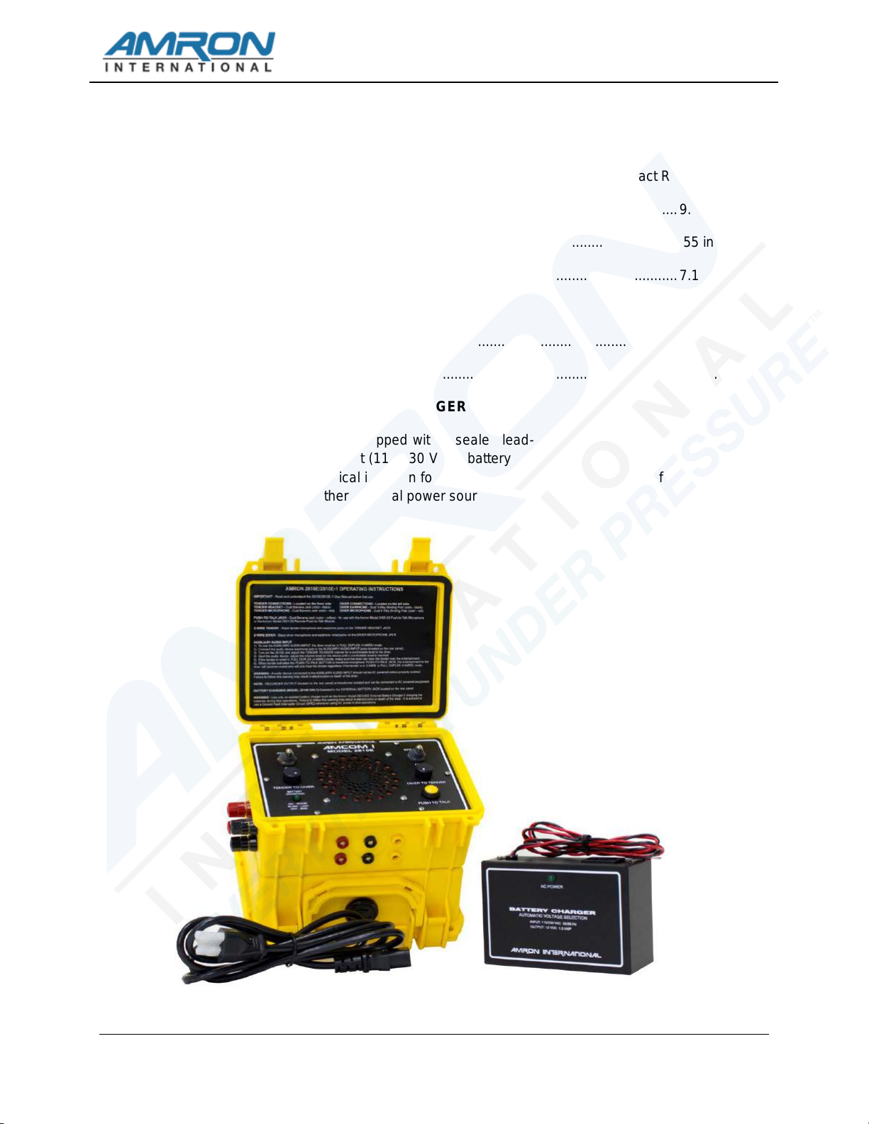
The 2810E is the newest member of the Amron International AMCOM I series of diver
communicators. The 2810E is a full featured, one-diver, hardwire communicator that uses
state-of-the-art electronics and introduces even more features to the diving community. The
first is a digital audio power amplifier which significantly reduces the current draw resulting in
a nearly doubling of the battery life. The 2810E uses a new audio filtering network for
improved sound clarity and communications. An auxiliary audio input allows the diver to
listen to audio from an MP3 player while remaining in constant communication with the
tender. Please note that this feature is only available when diving in 4-Wire mode. These
new features allow the AMCOM I 2810E to remain the most advanced one-diver
communicator on the market. To enjoy all the features, it is important that the tender read
and understand the entire manual including all warnings.
Like previous members of the AMCOM I family, the 2810E can operate in 2-Wire or Full
Duplex (4-Wire) communication modes. There is a single volume control for the up-link
(Diver-to-Tender) and another volume control for the down-link (Tender-to-Diver). Designed
for a long and dependable service life, the 2810E has a powder coated, stainless steel front
panel with a waterproof speaker and heavy-duty switches with waterproof seals. The 2810E
is enclosed in a rugged plastic case with all the user connectors situated so that the unit can
be operated with the case lid closed.
ELECTRICAL SPECIFICATIONS1.2
Input Impedance (Microphone Inputs) ..................................................................... 300 Ohms
Frequency Response.......................................................................................... 300 - 4000 Hz
Common Mode Rejection (minimum)................................................................................40 dB
Entertainment Input Impedance ..............................................................................>47 kOhms
Current Drain Maximum Full Volume...........................................................................3 Amps
Typical Quiescent.............................................................................55 mAmps
Minimum Load Impedance...............................................................................................2 ohm
Nominal Power Supply Voltage......................................................................................12 VDC
Operational Supply Voltage .....................................................................................9 - 18 VDC
Sensitivity (Input).....................................................................................................1.8 mVRMS
Maximum Output Power (4 Ohm Load, 14 VDC).........................................................20 Watts
Battery Life Model 2810E (typical) .............................................................................. 85 Hours
Model 2810E-1 (typical)......................................................................... 120 Hours

MODEL 2810E USER MANUAL
2810E UM REV 7.0
2
MECHANICAL SPECIFICATIONS1.3
Panel ........................................................................................Powder Coated Stainless Steel
Enclosure .................................................................................. High Impact Resistant Plastic
Size Length ..........................................................................................................9.0 in. (23cm)
Width..................................................................................................................6.55 in. (17cm)
Height...................................................................................................................7.1 in. (18cm)
Weight With Batteries
2810E............................................................................................................10.0 Lbs. (5.55kg)
2810E-1................................................................................................................7 Lbs. (3.2kg)
MODEL 2810E WITH BATTERY CHARGER1.4
The Model 2810E comes equipped with a sealed lead-acid rechargeable battery along with
the 2823-603 universal input (115/230 VAC) battery charger. The 2823-603 Battery Charger
has medical grade electrical isolation for maximum safety to the diver. Carefully read section
4.1 before using any other external power source.

MODEL 2810E USER MANUAL
2810E UM REV 7.0
3
MODEL 2810E-11.5
The Model 2810E-1 comes equipped with two lantern style, 6 Volt alkaline batteries. The unit
can be operated using an external power supply as described in the operation section of this
manual. Carefully read sections 3.4 and 4.3 before using any external power source.

MODEL 2810E USER MANUAL
2810E UM REV 7.0
4
2. WARRANTY AND SERVICE POLICY
LIMITED WARRANTY2.1
Amron warrants that its manufactured products are free from defects in material and
workmanship under normal use and service, as described in all literature covering the
products for a period of 90 days from date of shipment. Amron’s obligations under this
warranty are limited to the repair of, or replacement of materials at Amron’s discretion. This
warranty shall not cover defects which are the result of misuse, negligence, accident, repair,
or alterations.
SERVICE POLICY
2.2
For technical assistance or to request a repair, please call (760) 208-6500, Monday –
Friday, 8 a.m. to 5 p.m. PT. Have the model number and serial number handy and be
prepared to offer as much information as possible about the problem.
Please do not return any product without obtaining a return authorization number. Detailed
instructions will be provided at the time of request.

MODEL 2810E USER MANUAL
2810E UM REV 7.0
5
3. ACCESSORIES
Amron produces a series of accessories designed to operate with the entire line of AMCOM diving
communicators.
AMRON HEAVY-DUTY HEADSET - MODEL 2401-283.1
The Model 2401-28 is a heavy-duty headset with boom microphone. It comes equipped with
color-coded, dual banana plugs that mate directly to AMCOM diver communicators. It
includes a six foot (1.8 meter) cord.
AMRON STANDARD HEADSET - MODEL 2460-283.2
The Model 2460-28 is a light and comfortable headset designed for extended wear at an
economical price. It comes equipped with color-coded, dual banana plugs that mate directly
to AMCOM diver communicators as well as a spiral cord that can be extended up to 8 feet
(2.4 meters).
AMRON PUSH-TO-TALK MICROPHONE - MODEL 2405-283.3
The Model 2405-28 is a hand-held, noise canceling, push-to-talk microphone that provides
excellent sound quality to the diver. It comes equipped with a spiral cord that can be
extended up to 6 feet (1.8 meters).
AMRON REMOTE WALK-AND-TALK MODULE - MODEL 2822-283.4
Designed for Full Duplex (4-Wire) applications, the Model 2822-28 provides the tender with
mobility around the dive site while maintaining communications with the diver. It comes
equipped with a small clip-on belt module that contains the connectors for the headset, and
25 feet (7.6 meters) of lightweight flexible cable. Custom cable lengths are available.
AMRON REMOTE PUSH-TO-TALK MODULE - MODEL 2821-283.5
Designed for 2-Wire applications, the Model 2821-28 provides the tender with mobility
around the dive site while maintaining communications with the diver. It comes equipped
with a small clip-on belt module that contains a Push-to-Talk switch, connector for the
headset, and 25 feet (7.6 meters) of lightweight flexible cable. Custom cable lengths are
available.
AUDIO ADAPTOR CABLE - AMRON PART NUMBER 180-1000-003.6
A 2 meter long cable with two RCA Phono plugs that connect the auxiliary audio input to a
standard 3.5 mm stereo phone plug which mates to the headphone jack of most common
portable audio devices.

MODEL 2810E USER MANUAL
2810E UM REV 7.0
6
4. CONTROLS AND CONNECTIONS
Before using the 2810E diver communicator, the tender should be familiar with all the operating
controls and connections. While reading this manual, you will find capitalized words such as PANEL
SPEAKER. These words are to remind the reader that additional information can be found in this
section of the manual.
TENDER AND DIVER CONTROLS4.1
The following controls are located on the front panel of the 2810E
4.1.1 POWER SWITCH - The power on/off control.
4.1.2 SPEAKER SWITCH - This switch allows the tender to turn off the speaker. If the
tender is using a headset, it may be necessary to turn off the speaker in order to
prevent acoustic feedback.
4.1.3 PUSH-TO-TALK BUTTON - This button allows the tender to talk to the diver when
operating in the 2-Wire mode. It is not necessary to use this control in the Full
Duplex (4-Wire) mode. When using Full Duplex mode, this control allows the
tender to interrupt the diver by forcing the diver into listen only mode.
4.1.4 TENDER TO DIVER VOLUME - This control sets the volume for the diver's
earphone including any signal from the AUXILIARY AUDIO INPUT. Rotate this
knob clockwise to increase the volume.

MODEL 2810E USER MANUAL
2810E UM REV 7.0
7
4.1.5 DIVER TO TENDER VOLUME - This control sets the volume for the tender's
earphone and/or panel speaker. Rotate this knob clockwise to increase the
volume.
4.1.6 PANEL SPEAKER - A waterproof, acoustic speaker that allows the tender to
monitor communication to the diver and act as a microphone by using the PUSH-
TO-TALK BUTTON. The volume level is controlled by the DIVER TO TENDER
VOLUME control and it can be turned off using the SPEAKER SWITCH.
4.1.7 BATTERY CONDITION INDICATOR - This LED is used by the tender to determine
the available battery level. A steady green light means that the battery charge level
is greater than 30%. When the battery reaches approximately 30% remaining life,
the LED will start blinking at a rate of about once per second. When the battery
reaches its end-of-charge, the LED will turn off and the 2810E will go into
shutdown mode to prevent damaging the communicator or rechargeable battery. It
is advised that the 2810E with rechargeable battery be connected to the charger
as soon as possible once the BATTERY CONDITION INDICATOR starts blinking.
While there should be enough time to safely complete a normal diving operation,
the exact amount of time is dependent on the age and condition of the sealed lead
acid battery.
TENDER CONNECTIONS4.2
The tender connections are located on the front side of the 2810E communicator.
4.2.1 TENDER HEADSET - This is the dual banana jack (color-coded black) that
functions as both an output (earphone) and input (microphone) for the tender as

MODEL 2810E USER MANUAL
2810E UM REV 7.0
8
controlled by the PUSH-TO-TALK BUTTON and PUSH-TO-TALK JACK. Using this
connection, the tender can be wired in either 2-Wire or Full Duplex (4-Wire) mode
regardless of the mode used for the diver.
To connect the tender in the Full Duplex (4-Wire) mode, connect the earphone
(black) banana plug of the headset to this jack and the microphone (red) to the
TENDER MICROPHONE jack (red) as shown in the wiring diagram in section 3.6.
In this mode, the tender does not have to use the PUSH-TO-TALK BUTTON to
communicate with a diver who is also connected in the Full Duplex (4-Wire) mode.
This configuration can be used even if the diver is connected in 2-Wire mode. In
that situation, the tender is required to use the PUSH-TO-TALK BUTTON or
PUSH-TO-TALK JACK.
The headset microphone is always active which means that there can be acoustic
feedback between the PANEL SPEAKER and the microphone if the tender is near
the 2810E. To prevent this, the PANEL SPEAKER can be turned off using the
SPEAKER SWITCH. Another option is to move the tender away from the 2810E by
using the Amron Model 2822-28 Walk-and-Talk Module accessory. This allows the
tender to communicate while other members of the surface crew listen using the
PANEL SPEAKER. This module comes with 25 feet (7.6 meters) of cable (custom
cable lengths are available).
The tender can also be connected in 2-Wire mode by stacking both the earphone
(black) and microphone (red) banana plugs into this jack as shown in the wiring
diagram in section 3.5. The diver does not have to be connected in 2-Wire mode if
the tender is in 2-Wire mode. In order to talk to the diver, the tender must use
either the PUSH-TO-TALK BUTTON or PUSH-TO-TALK JACK. Since the headset
microphone is not active until one of the push-to-talk methods is used, there is no
chance for acoustic feedback to occur and surface conversation or noise is not
transmitted to diver and the PANEL SPEAKER can be left on. This may, for some
situations, make for a better overall diving experience. If the tender requires more
mobility at the dive site, the Amron Model 2821-28 Remote Push-to-Talk Module
can be used to extend the headset cable. It includes a push-to-talk button on a
clip-on belt module and comes standard with 25 feet (7.6 meters) of cable (custom
cable lengths are available).
The tender may also use the optional Amron Model 2405-28 Push-to-Talk
Microphone. This microphone comes with two color-coded banana plugs. The
black plug goes into the TENDER HEADSET jack and the yellow plug goes in the
PUSH-TO-TALK JACK as shown in the wiring diagram in section 3.7. To
communicate with the diver, the tender presses the button on the side of the
microphone. There is no chance of acoustic feedback since the PANEL SPEAKER
is cut-off when the tender uses the microphone. When using the Push-to-Talk
Microphone, the SPEAKER SWITCH must be turned on in order to hear the diver.
4.2.2 TENDER MICROPHONE - This is a dual banana jack (color-coded red) that
functions as the microphone input from the tender's headset. It is only used if the
tender is in Full Duplex (4-Wire) mode.

MODEL 2810E USER MANUAL
2810E UM REV 7.0
9
4.2.3 PUSH-TO-TALK JACK - This is a dual banana jack (color-coded yellow) that
allows for remote keying of the push-to-talk function of the 2810E. The difference
between using the PUSH-TO-TALK JACK and PUSH-TO-TALK BUTTON is that
the button allows the tender to communicate using the PANEL SPEAKER as a
microphone. If both are used at the same time, the PANEL SPEAKER is active as
a microphone. This allows a crew member to talk to the diver using the PANEL
SPEAKER even if the tender is away from the 2810E using the Remote Push-to-
Talk Module in 2-Wire mode.
DIVER CONNECTIONS4.3
The diver connections are located on the left side of the communicator.
4.3.1 DIVER MICROPHONE - This is a dual 5-way binding post jack (color-coded red)
that functions as both an output (earphone) and input (microphone) for the diver as
controlled by the PUSH-TO-TALK BUTTON and PUSH-TO-TALK JACK. Using this
connection, the diver can be wired in either 2-Wire or Full Duplex (4-Wire) mode
regardless of the mode used for the diver.
To connect the diver in Full Duplex (4-Wire) mode, connect the diver microphone
to this jack and the diver earphone the DIVER EARPHONE jack as shown in the
wiring diagram in section 3.6. The diver can use this mode even if the tender is
wired in 2-Wire mode.
To connect the diver in 2-Wire mode, connect both the diver microphone and
earphone to this jack. If the diver umbilical uses banana plugs, simply stack both
plugs into this jack as shown in the wiring diagram in section 3.5. In this mode, the
diver microphone will be active and heard on tender headset and/or PANEL

MODEL 2810E USER MANUAL
2810E UM REV 7.0
10
SPEAKER unless the PUSH-TO-TALK BUTTON or PUSH-TO-TALK JACK is
activated.
4.3.2 DIVER EARPHONE - This is a dual 5-way binding post jack (color-coded black)
that functions as the output for the diver's earphone. It is only used when the diver
is in Full Duplex (4-Wire) mode.
REAR PANEL CONNECTIONS4.4
4.4.1 EXTERNAL BATTERY JACK - The 2810E can be powered using an external
battery or power supply via the two color coded TIP jacks. The red TIP jack is the
positive power input and the black is the negative power input. The input voltage
must be between 9 and 18 VDC and must be able to supply a peak current of 3
Amps for proper operation. The following warnings need to be heeded when using
the EXTERNAL BATTERY JACK. A minimum wire size of 18 AWG and maximum
wire run of 3 feet (1 meter) are recommended.
WARNING!
When using the EXTERNAL BATTERY input with the 2810E-1 (non-
rechargeable battery) current can flow into the alkaline batteries and, with
prolonged use or high current, cause the battery to leak. To prevent this, it
is advised that the alkaline batteries be disconnected or removed from the
unit when an external power supply is used.

MODEL 2810E USER MANUAL
2810E UM REV 7.0
11
4.4.2 RECORDER OUTPUT - This is a single RCA Phono jack (color-coded black) that
provides a transformer isolated of both the diver and tender communications. It is
designed to drive the standard line-level inputs of audio or video recorders with
input impedances as low as 600 Ohms. The RECORDER OUTPUT will not record
the signal from the AUXILIARY AUDIO INPUT.
4.4.3 AUXILIARY AUDIO INPUT - This is a set of two RCA Phone jacks (color-coded
red and white) that provides a means to connect an external audio signal for diver
entertainment. Although this input will accept a stereo audio source, it will be
converted into a monaural signal before going to the diver. This signal is not heard
in either the tender headset or via the PANEL SPEAKER. The earphone output of
most MP3 players can be connected to this input using an adaptor cable like the
Amron Audio Adaptor Cable (Amron Part Number 180-1000-00). This feature will
only work if the diver is wired in Full Duplex (4-Wire) mode.
There is no separate volume control provided for the diver entertainment signal.
The audio device provides the volume control. It is advised at the start of diving
operation, and before the external audio device is turned on, that the tender adjust
and verify the TENDER TO DIVER VOLUME level is correct and comfortable for
the diver. Then starting with the lowest volume, adjust the volume on external
device until a comfortable level is achieved. If the tender is connected in the Full
Duplex (4-Wire) mode, the volume level should not be so loud as to prevent the
diver from hearing the tender. If the tender is connected in the 2-Wire mode, then
the entertainment will be cut off whenever the PUSH-TO-TALK BUTTON or PUSH-
TO-TALK JACK is used. The PUSH-TO-TALK BUTTON can be used by the tender
to cut off the entertainment even if the tender is connected in the Full Duplex (4-
Wire) mode.
WARNING!
The EXTERNAL BATTERY input can be used to recharge the 2810E rechargeable sealed lead acid battery. It is
strongly advised to use the provided Amron External Charger, Model 2823-603, to charge or operate the
communicator. This charger has been designed with the necessary electrical isolation to prevent dangerous
currents from the AC lines from reaching the diver.
If you use an external power supply, the maximum voltage needs to be limited to 15 Volts if the rechargeable
battery is in the unit. If a higher voltage is to be used, it is advised that the battery be disconnected or removed
from the communicator to prevent possible damage to the battery.

MODEL 2810E USER MANUAL
2810E UM REV 7.0
12
DRAWING, 2-WIRE CONNECTIONS4.5

MODEL 2810E USER MANUAL
2810E UM REV 7.0
13
DRAWING, FULL DUPLEX (4-WIRE) CONNECTIONS4.6

MODEL 2810E USER MANUAL
2810E UM REV 7.0
14
DRAWING, PUSH-TO-TALK MICROPHONE CONNECTIONS4.7

MODEL 2810E USER MANUAL
2810E UM REV 7.0
15
5. OPERATION
The 2810E comes in a yellow, rugged plastic case. To gain access to the front panel, open the case
by releasing both latches on the front of the unit. To gain access to the battery compartment, turn
the unit over and release both latches on the front of the unit.
CHARGING THE BATTERY (2810E ONLY)5.1
The Model 2810E is supplied with a sealed lead acid battery. To charge the battery, connect
the 2823-603 Battery Charger to the EXTERNAL BATTERY JACK located on the back of the
unit. Following the color coding of the jack, connect the red plug to the red jack and the black
plug to the black jack. The Amron Model 2823-603 charger is able to operate on 115 and
230 VAC lines without the user having to make any adjustments.
The 2823-603 Battery Charger is designed to charge the battery in float mode so the charger
can be left on indefinitely, without damage, to ensure the battery is fully charged and the unit
is ready to use. A fully discharged battery will take approximately 10 hours to reach full
charge (depending on the age of the battery and the surrounding temperature). To ensure
maximum service life, the battery should be fully charged at least once every six months.
The operating time for a fully charged battery is approximately 85 hours. The exact operating
time depends on the age of the battery and the ambient temperature. The sealed lead acid
battery used in the 2810E has a service life of 300 full charge/discharge cycles or 3 years.
The BATTERY CONDITION INDICATOR will start to blink when the battery has
approximately 30% remaining charge. To maximize the service life, the battery should be
recharged as soon as possible after the indicator starts to blink. When the battery reaches
the full discharge state, the 2810E will shutdown to prevent damage to both the battery and
the electronics.
INITIAL POWER ON - BATTERY CONDITION CHECK5.2
Turn all the volume controls to minimum and turn on the POWER SWITCH. The state of the
battery is shown on the BATTERY CONDITION INDICATOR as follows:
•STEADY GREEN - the battery is good and has more than 30% remaining life
•BLINKING GREEN - the battery is low and has less than 30% remaining life
•OFF or NO LIGHT - the battery is depleted and needs to be changed/recharged before
use
The BLINKING GREEN light provides a warning that the battery is low and should be
changed or recharged before starting the dive operation. When the indicator starts
BLINKING GREEN during dive operations, there is, depending on age of the battery and the
ambient temperature, approximately 24 hours of remaining life for the 2810E and
approximately 36 hours for the 2810E-1. This should be sufficient time to safely complete
dive operations. A battery that has not been used for a long period of time will exhibit a
higher voltage than the actual charge state. This is known as surface charge and will quickly
dissipate once the unit is turned on. It is recommended that the unit be left on for 5 minutes
before relying on the BATTERY CONDITION INDICATOR.

MODEL 2810E USER MANUAL
2810E UM REV 7.0
16
OPERATING ON AC POWER5.3
As noted in section 3.4 on the EXTERNAL BATTERY JACK, it is possible to operate the
2810E with an external AC power supply. Review all warnings in this section and section 3.4
before using an AC power supply.
It is strongly advised that the 2810E only be operated for AC Power when using the Amron
Model 2823-603 Battery Charger. Amron has designed the 2823-603 with medical grade
electrical isolation that prevents any possible leakage of AC current into the 2810E
communicator. This protects the diver and tender from electrocution.
The 2823-603 Battery Charger can also be used to power the 2810E-1. It is recommend that
if the battery charger is going to be used for an extended period of time, the alkaline
batteries should be removed to prevent possible leakage.
MODES OF OPERATION5.4
The Models 2810E and 2810E-1 have the ability to operate in either 2-Wire or Full Duplex
(4-Wire). Both the diver and tender can be connected in either mode and a combination of
modes can be used. For example, the diver can be connected in Full Duplex (4-Wire) mode
to take advantage of the new entertainment feature while the tender is wired in 2-Wire mode.
If either the diver or the tender is wired in 2-Wire mode, the tender must use a push-to-talk,
either the PUSH-TO-TALK BUTTON or PUSH-TO-TALK JACK, when talking to the diver.
2-Wire communication is defined as a single communication path, normally the diver is the
priority signal path –tender listens to diver. Signal reversing is accomplished by pushing the
PUSH-TO-TALK BUTTON –diver hears tender. Often times a 4-conductor communication
cable is used with 2 wires tied together as a pair for redundancy, this is still a 2-Wire system.
Since only one person can talk at a time, there is a level of discipline that goes with using 2-
Wire mode in order to obtain clear communication. One advantage of 2-Wire is that the
tender's microphone is not active unless one of the two push-to-talk controls, PUSH-TO-
TALK BUTTON or PUSH-TO-TALK JACK, are active. This eliminates any possible acoustic
feedback between the tender's microphone and the PANEL SPEAKER. It also prevents
noise from the surface reaching the diver and allows the tender to communicate with other
members of the surface crew without involving the diver. If the diver is connected in 2-Wire
mode, the AUDIO AUXILIARY INPUT cannot be used to deliver entertainment to the diver.
WARNING!
When operating your Amron Diver Communicator from AC mains, it is critical to use a
Ground Fault Circuit Interrupter (GFCI) and/or isolation transformer for tender and diver
safety. Surges and spikes are common on AC lines found onboard ships, from local
generators, or at the end of a long extension lines. These spikes can exceed 1kV! Such
spikes can be high enough to cause the input fuses on the Amron Model 2823-603
Battery Charger to blow and, in extreme cases, actually damage the charger circuitry.
Amron has designed this battery charger to isolate such faults to ensure that they will not
cause a safety issue for the diver or tender. Amron cannot guarantee that non-Amron
power supplies meet the same high standards and strongly advises against using any
such device to power your diver communicator.
This manual suits for next models
1
Table of contents
Other Amron Cell Phone manuals

Amron
Amron 2830A/24 Series User manual

Amron
Amron 2820A User manual

Amron
Amron 2820A-02 User manual

Amron
Amron Amcom II 2825R/24 Series User manual

Amron
Amron 2820A-4003 User manual

Amron
Amron 2825A User manual

Amron
Amron 2810E-02 User manual

Amron
Amron AMCON II 2825R Series User manual

Amron
Amron 2820A User manual

Amron
Amron 2820A User manual