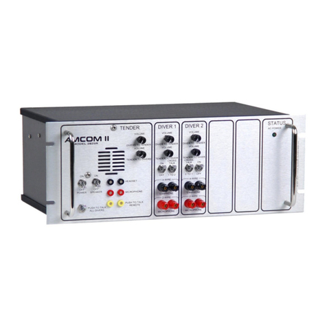
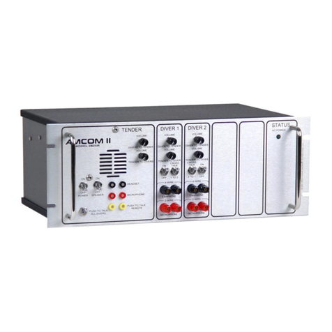
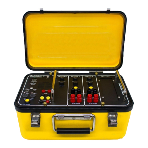
Amron 2820A User manual

Instruction Manual
For
Amron International, Inc.
Model 2820A& 2825A
Two Diver Communicator
S/N______________________
1380 Aspen Way, Vista California 92081-8349
United States of America
Phone: (760) 208-6500
Fax (760) 599-3857
email: [email protected]
web: www.amronintl.com
This manual and the information contained herein are provided for use as an operation and
maintenance guide. No license or rights to manufacture, reproduce, or sell either the manual or
articles described herein are given. Amron International, Inc. reserves the right to change
specifications without notice. Copyright© 2013 Amron International, Inc.

MODEL 2820A-25A USER MANUAL
2820A-25A-UM REV 3.0
i
TABLEOFCONTENTS
1.INTRODUCTIONANDSPECIFICATIONS...........................................................................................1
1.1Introduction.................................................................................................................................1
1.2ELECTRICAL Specifications ......................................................................................................1
1.3Mechanical SPECIFICATIONS...................................................................................................2
1.4Drawing Front Panel Controls Model 2820A ..............................................................................3
1.5Drawing Front Panel Controls Model 2825A ..............................................................................4
2.LIMITEDWARRANTYANDSERVICEPOLICY....................................................................................5
2.1Limited Warranty.........................................................................................................................5
2.2Service Policy .............................................................................................................................5
3.OPTIONSANDACCESSORIES..........................................................................................................6
3.1Options........................................................................................................................................6
3.2Accessories.................................................................................................................................6
4.CONTROLSANDCONNECTIONS.....................................................................................................8
4.1Tender Controls..........................................................................................................................8
4.2Tender Connections....................................................................................................................9
4.3Diver Controls.............................................................................................................................9
4.4Diver Connections.......................................................................................................................9
4.5Other Connections....................................................................................................................10
4.6Option Controls Helium Speech Unscrambler/26DSP2 ...........................................................10
4.7Option Controls Wireless Tender /28A Option .........................................................................11
4.8Drawing 2-Wire Connections....................................................................................................13
4.9Drawing, Full Duplex (4-Wire) Connections .............................................................................14
4.10Drawing, Operator Connections, P-T-T. Microphone...............................................................15
4.11Drawing, Operator Connections, Headset................................................................................16
5.INSTALLATIONANDOPERATION..................................................................................................17
5.1Operation..................................................................................................................................17
5.2Charging the Batteries: /23 and /24 Rechargeable Units.........................................................17
5.3Battery Condition ......................................................................................................................18
5.4Battery Installation: Standard and /23 Rechargeable Units......................................................18
5.5Battery Installation:/24 AC Powered Units................................................................................19
5.6Modes of Operation ..................................................................................................................19
5.7Volume Controls – 2-Wire.........................................................................................................20
5.8Other Diver Controls – (2-Wire)................................................................................................21
5.9Volume Controls – 4-Wire (full duplex).....................................................................................21
5.10Other Diver Controls (4-Wire Mode).........................................................................................22
5.11Other Tender Controls..............................................................................................................22
5.12Wireless Options.......................................................................................................................24
6.MAINTENANCEANDTROUBLESHOOTING....................................................................................26
6.1Full duplex (4-wire) Check........................................................................................................26
6.22-wire check..............................................................................................................................26
6.3General Maintenance................................................................................................................27
6.4TROUBLESHOOTING..............................................................................................................28
MODEL 2820A-25A USER MANUAL
2820A-25A-UM REV 3.0
ii
7.FULLDUPLEX(4‐WIRE)–WHAT,WHYANDHOW.........................................................................33
7.1What are 2-Wire and 4-Wire modes?.......................................................................................33
7.2What is Full Duplex (4-Wire)?...................................................................................................34
7.3Why Full Duplex (4-Wire)?........................................................................................................35
7.4How Do You Use Full Duplex (4-Wire)?...................................................................................35
8.DRAWINGSANDSCHEMATICS.....................................................................................................37
8.1Schematic 2820A and 2820A/23..............................................................................................38
8.2Schematic 2820A/24.................................................................................................................39
8.3Schematic 2825A and 2825A/23..............................................................................................40
8.4Schematic 2825A/24.................................................................................................................41
8.5Schematic Option /26DSP2......................................................................................................42
8.6Schematic Option 2828-100A...................................................................................................43
8.7Parts Identifier Front Panel Model 2820A.................................................................................44
8.8Parts Identifier, Front Panel Model 2825A................................................................................45
8.9Parts Identifier, Models /24, 224/26DSP2 & /24/28A Option....................................................46
9.PARTSLISTS.................................................................................................................................47
9.1Amcom II Model 2820A ............................................................................................................48
9.2Amcom II Model 2820A/23 .......................................................................................................49
9.3Amcom II Model 2820A/24 .......................................................................................................50
9.4Amcom II Model 2825A ............................................................................................................51
9.5Amcom II Model 2825A/23 .......................................................................................................52
9.6Amcom II MODEL 2825A/24 ....................................................................................................53
9.7Amcom II Model 2825A/24/26DSP2.........................................................................................54
9.8AMCOMM II MODEL 2825A/24/26DSP2 (continued)..............................................................55
9.9Amcom II Model 2825A/23/28A................................................................................................56
9.10Amcom II Model 2825A/24/28A................................................................................................57
9.11AMCOM II MODEL 2825A/24/28A (continued)........................................................................58
9.122820-301 Case Assembly – AMCOM II....................................................................................58
9.132820A-400M Front Panel Assembly.........................................................................................58
9.142825A-400M Front Panel Assembly.........................................................................................59
9.152820-500 Battery Box...............................................................................................................60
9.162824-500B Battery Box Internal Charger..................................................................................60
9.172823-603 External Charger Assembly......................................................................................61
9.1828xx-FS-01 Field Spares Kit for 2820A, 2825A........................................................................62
9.19Optional Spares........................................................................................................................62

MODEL 2820A-25A USER MANUAL
2820A-25A-UM REV 3.0
1
1. INTRODUCTION AND SPECIFICATIONS
1.1 INTRODUCTION
The AMCOM II Series of diver communication systems are full featured hard-wired, two-
diver communicators. The AMCOM II is offered in two basic versions; the units are identical
except the Model 2825A has independent microphone and earphone volume controls for
each diver and the tender. The Model 2820A has a single earphone volume control for
diver’s volume (down-link) and a single volume control for the tender (up-link).
All AMCOM II series have push-to-talk and separate isolated inputs for each diver. The
AMCOM II Model 2820A and Model 2825A are portable two diver communication systems,
delivering 20 Watts “voice power”, operating from internal batteries or external 12 VDC
power source.
Models with the /24 option can be operated from either a 110/220 VAC, external 12 VDC
power source, or an internal 12 VDC battery.
The 2820A and 2825A have the capability of 2-wire and/or Full Duplex (4-wire)
communication modes. 2-Wire and Full Duplex (4-wire) modes can be used simultaneously.
Full Duplex is a communications system designed from the “ground-up” to take advantage of
the current “state-of-the-art” in semiconductor technology and provide superior diver hard
wire communication.
This portable diving radio has the ability to work with both dynamic and pre-amplified
microphones in either 2-wire or 4-wire modes. The circuit detects the type of microphone
that each diver is using then automatically switches from the preamp mode to dynamic
mode, adjusting the specific diver’s gain (volume). The tender’s volume is set louder than the
diver’s volume. This allows the tender to hear the divers in a noisy environment while
maintaining the diver’s volume at a comfortable level.
1.2 ELECTRICAL SPECIFICATIONS
Input Impedance (Each Input)................................................................................... 250 Ohms
Frequency Response........................................................................................ 300 - 10000 Hz
Common Mode Rejection..................................................................................40 dB Minimum
Current Drain Maximum Full Volume.............................................................................3 Amps
Minimum Quiescent...................................................................................................0.25 Amps
Output Impedance........................................................................................................... 4 Ohm
Power Supply Voltage.....................................................................................12 VDC Nominal
(9 Volts Minimum - 18 Volts Maximum)
Sensitivity (Input).............................................................................................................0.5 mV
Output Power (RMS @ 4 Ohm Load, 12 VDC)..................................................20 Watts Audio
Battery Life
Model 2820A & 2825A …………………………… ...………………………….………….40 Hours
Model 282XA/23 …………….……………..…... ………………………………………….30 Hours

MODEL 2820A-25A USER MANUAL
2820A-25A-UM REV 3.0
2
Model 282XA/24 …………….……………..…... ………………………………………….20 Hours
Operating Voltage ......................................................................................................... 12 VDC
Model 282XA/24.............................................................................90-264 Volts AC 47-440 Hz
1.3 MECHANICAL SPECIFICATIONS
Panel .....................................................................................Powder Coated Stainless Steel
Enclosure ....................................................................................High Impact Resistant Plastic
Enclosure Color................................................................................Bright International Yellow
Dimensions
Length ..........................................................................................................14.5 In. (36.8 Cm)
Width ............................................................................................................9.0 In. (22.9 Cm)
Height ..........................................................................................................10.0 In. (25.4 Cm)
Weight with Batteries
Model 2820A........................................................................................... 17.35 Lbs. (7.87 Kg)
Model 2820A/23 with External Charger .................................................. 20.53 Lbs. (9.31 Kg)
Model 2820A/24.................................................................................... 17.98 Lbs. (8.16 Kg)
Model 2825A........................................................................................... 18.20 Lbs. (8.26 Kg)
Model 2825A/23...................................................................................... 21.13 Lbs. (9.58 Kg)
Model 2825A/23/28A with Remote Wireless Tender Kit......................... 25.88 Lbs. (11.74 Kg)
Model 2825A/24...................................................................................... 18.53 Lbs. (8.40 Kg)
Model 2825A/24/26DSP2........................................................................ 19.18 Lbs. (8.70 Kg)
Model 2825A/24/28A with Remote Wireless Tender Kit......................... 23.28 Lbs. (10.56 Kg)

MODEL 2820A-25A USER MANUAL
2820A-25A-UM REV 3.0
3
1.4 AMCOM II MODEL 2820A DIVER COMMUNICATOR
The Model 2820A AMCOM II is a full featured, hardwire diver communicator. The 2820A features a
single earphone volume control for the divers (downlink) and a volume control for the tender (uplink).
Divers can be wired in either 2-Wire or 4-Wire mode for maximum flexibility. It can be ordered in the
following configurations:
Non-rechargeable lantern style batteries (2820A)
Rechargeable batteries with external charger (2820A/23)
Rechargeable batteries with internal charger (2820A/24 – Shown Above)

MODEL 2820A-25A USER MANUAL
2820A-25A-UM REV 3.0
4
1.5 AMCOM II MODEL 2825A DIVER COMMUNICATOR
The Model 2825A AMCOM II is a deluxe hardwire diver communicator. The 2820A features individual
earphone volume controls for each diver (downlink) as well as a volume control for the tender (uplink).
Both divers and the tender have microphone volume controls. Divers can be wired in either 2-Wire or 4-
Wire mode for maximum flexibility. It can be ordered in the following configurations:
Non-rechargeable batteries (2825A)
Rechargeable batteries with external charger (2825A/23)
Rechargeable batteries with internal charger (2825A/24 – Shown Above)
Rechargeable batteries with internal charger and Wireless Tender Option (2825A/24/28A)
Rechargeable batteries with internal charger and Helium Speech Unscrambler (2825A/24/26DSP2)

MODEL 2820A-25A USER MANUAL
2820A-25A-UM REV 3.0
5
2. LIMITED WARRANTY AND SERVICE POLICY
2.1 LIMITED WARRANTY
AMRON INTERNATIONAL, INC., (Amron) warrants that its products are free from defects in
material and workmanship under normal use and service, for a period of 90 days from date
of shipment as described in Amron literature covering this product. Amron’s obligation under
this warranty is limited to the repair of or replacement, at Amron’s option, of defective
material. This warranty shall not cover defects which are the result of misuse, negligence,
accident, repair or alterations.
2.2 SERVICE POLICY
For technical assistance or to request a repair, please call (760) 208-6500, Monday - Friday,
6 a.m. - 5 p.m. PST. Please do not return any product without an authorization number. After
obtaining a return authorization number, wrap and pack the item securely and ship to the
following address. We suggest that you use a carrier that provides tracking information and
insure the item for full replacement value:
Amron International, Inc.
Attn: Repairs Department
1380 Aspen Way
Vista, CA. 92081
Be sure to reference the return authorization number on the outside of the shipment. For
non-warrantable repairs, a minimum evaluation fee will be charged. A written evaluation and
quote will be provided for approval before Amron proceeds with the repairs.

MODEL 2820A-25A USER MANUAL
2820A-25A-UM REV 3.0
6
3. OPTIONS AND ACCESSORIES
3.1 OPTIONS
Amron offers the following options for the AMCOM II communicator:
3.1.1 Model /23 – External Battery Charger - The communicator is equipped with 4 gel-cell
sealed lead-acid batteries and includes an external universal input (115/230 VAC)
battery charger. Operating time is approximately 30 hours.
3.1.2 Model /24 – Internal Battery Charger - The communicator is equipped with an
internal universal input (115/230 VAC) battery charger along with a rechargeable
battery. Operating time is approximately 20 hours.
3.1.3 Model /26DSP2 - The communicator is equipped with Amron DSP2 Helium Speech
Unscrambler (HSU). The DSP2 is an advanced, dual mode HSU with a range from
surface to 2000 FSW (600 MSW). This option must be ordered with the /24 option
and only on the 2825A.
3.1.4 Model /28A – Wireless Tender Option - The communicator is equipped with a
wireless module and includes a Model 2829-11 Wireless Tender Headset. The
wireless headset allows the tender freedom to move around. It requires the divers
are wired in 4-Wire mode. This options is available on the 2825A only.
3.2 ACCESSORIES
Amron produces a series of accessories designed to operate with the entire line of AMCOM
communicators.
3.2.1 Amron Heavy-Duty Headset - Model 2401-28 - The Model 2401-28 is a heavy-duty
headset with boom microphone. It comes equipped with color-coded, dual banana
plugs that mate directly to AMCOM diver communicators. It includes a six foot (1.8
meter) cord.
3.2.2 Amron Standard Headset - Model 2460-28 - The Model 2460-28 is a light and
comfortable headset designed for extended wear at an economical price. It comes
equipped with color-coded, dual banana plugs that mate directly to AMCOM diver
communicators as well as a spiral cord that can be extended up to 8 feet (2.4
meters).
3.2.3 Amron Push-to-Talk Microphone - Model 2405-28 - The Model 2405-28 is a hand-
held, noise canceling, push-to-talk microphone that provides excellent sound quality
to the diver. It comes equipped with a spiral cord that can be extended up to 6 feet
(1.8 meters).
3.2.4 Amron Remote Walk-and-Talk Module - Model 2822-28 - Designed for Full Duplex
(4-Wire) applications, the Model 2822-28 provides the tender with mobility around
the dive site while maintaining communications with the diver. It comes equipped
with a small clip-on belt module that contains the connectors for the headset, and 25
feet (7.6 meters) of lightweight flexible cable. Custom cable lengths are available.

MODEL 2820A-25A USER MANUAL
2820A-25A-UM REV 3.0
7
3.2.5 Amron Remote Push-to-Talk Module - Model 2821-28 - Designed for 2-Wire
applications, the Model 2821-28 provides the tender with mobility around the dive
site while maintaining communications with the diver. It comes equipped with a
small clip-on belt module that contains a Push-to-Talk switch, connector for the
headset, and 25 feet (7.6 meters) of lightweight flexible cable. Custom cable lengths
are available.
3.2.6 Amron Wireless Tender Headset – Model 2829-11 - A heavy-duty headset
combined with a wireless belt module that is compatible with the /28A option. One
headset comes with communicators ordered with the /28A options but additional
headset can be ordered to allow other crew member to monitor communications.

MODEL 2820A-25A USER MANUAL
2820A-25A-UM REV 3.0
8
4. CONTROLS AND CONNECTIONS
Before using the AMCOM II series diver communications system, you should familiarize yourself
with its operating controls and connections. Improper use of controls and connections will deprive
the user of the full benefits of this communication system. We also recommend reading the FULL
DUPLEX description located in the Operation Section of this manual, for an explanation of
advantages and "How to Implement" your AMCOM II Communications System.
4.1 TENDER CONTROLS
4.1.1 POWER SWITCH - Applies power to the unit from internal batteries or from external
source.
4.1.2 SPEAKER SWITCH - Turns panel speaker and microphone on/off. It may be
necessary to turn speaker off when using a headset to prevent feedback.
4.1.3 PUSH-TO-TALK ALL DIVERS SWITCH – This Switch allows tender to divers
communication in 2-wire mode. (No push-to-talk required when operating in Full
Duplex, 4-wire mode). In Full Duplex mode this switch allows the tender to interrupt
divers with a priority message; all divers will be listening.
4.1.4 EARPHONE VOLUME - Controls panel speaker and/or tender headset volume. Use
as master volume control, clockwise increases volume.
4.1.5 MICROPHONE VOLUME (Model 2825A only) - Controls tender microphone volume.
Use as master volume control, clockwise increases volume.
4.1.6 BATTERY CONDITION INDICATOR – Steady GREEN light indicates battery
voltage level is good. Blinking GREEN light indicates battery voltage is approaching
a low level. Steady RED light indicates battery voltage is below the level necessary
to guarantee proper operation.
WARNING!
When Battery Condition indicator is steady RED light, communication will stop.
4.1.7 PANEL SPEAKER - Acoustic horn speaker; operates when Speaker Switch is ON.
4.1.8 PANEL MICROPHONE - Condenser microphone to pick up tender voice, it operates
when Speaker Switch is ON and PTT Switch is depressed.
WARNING!
Do not place any objects in the Panel Microphone hole or damage can occur. Do not cover or plug the
Panel Microphone hole with any debris or improper performance will occur.

MODEL 2820A-25A USER MANUAL
2820A-25A-UM REV 3.0
9
4.2 TENDER CONNECTIONS
4.2.1 HEADSET JACK (output/input) - Is a dual banana jack (color coded black)
connection for headset earphones. It functions as an earphone (output) and a
microphone (input) when PTT switches depressed. In 2-wire mode of operation both
headset microphone and earphones are plugged into this jack, conversations (up-
link & down-link) are switched automatically when push-to-talk switch is actuated. In
Full Duplex mode this jack is an earphone only, both up-link & down-link
conversations are heard.
4.2.2 MICROPHONE JACK (input) - Is a dual banana jack (color coded red) connection
for the headset microphone. Tender microphone volume control adjusts the
sensitivity of the input.
4.2.3 PUSH-TO-TALK JACK Is a dual banana jack (color coded yellow) connection for
remote keying of PUSH-TO-TALK switch It is use by the Push-To-Talk Microphone
(Amron Model 2405-28) and the Remote Walk-And-Talk Module (Amron Model
2822-28..
4.3 DIVER CONTROLS
4.3.1 Diver Volume Model 2820A – Controls both divers 1 & 2 earphone volumes.
4.3.2 MICROPHONE Volume Model 2825A (Divers 1 & 2) - Controls amplification of
diver’s microphone signal, therefore control diver’s volume to tender and to all
divers. Each diver circuit has its own volume control.
4.3.3 EARPHONE Volume Model 2825A (Divers 1 & 2) - Controls diver’s earphone signal,
therefore controls diver’s hearing volume from tender and to all divers. Each diver
circuit has its own volume control.
4.3.4 PUSH-TO-TALK- (Diver 1 & 2) - Momentary switch which allows a specific diver to
hear tender and all divers (diver switches to listening mode) as long as switch is
depressed, used in the two-wire mode.
4.4 DIVER CONNECTIONS
4.4.1 MICROPHONE (input/output) (Applies to Divers 1 & 2) - This connector is a dual 5-
Way Binding Post Jack (color coded red). It functions as a microphone (input) and
as an earphone (output) when PTT switch is depressed (used in both 2 & 4-wire
mode).
In the 2 wire mode of operation, both diver microphone and earphone banana plugs
are stacked into the umbilical microphone jack (red binding posts). Conversations
(up-link & down-link) are switched automatically when push-to-talk switch is
actuated. When a pre-amp microphone is used in the 2-wire mode setup, it is
required to have special speakers supplied only by Amron.
In Full Duplex (4-wire) mode, only the diver microphone banana plug is connected
into the umbilical microphone jack.

MODEL 2820A-25A USER MANUAL
2820A-25A-UM REV 3.0
10
4.4.2 EARPHONE Jack (output) – 4 Wire, (Diver 1 & 2) - This connector is dual 5-Way
Binding Post Jack (color coded black). It is the connection point for the diver’s
earphone when operating in the Full Duplex mode (4-wire).
4.5 OTHER CONNECTIONS
4.5.1 EXTERNAL BATTERY - (Input) - External 12 VDC power input to operate the unit
from an external battery or power source. Power requirements are 12 volts DC
(nominal), not less than 9.5 or more than 18 volts. Source must be able to supply a
peak current of three amps for proper operation. With the model /23 Option these
jacks are used for charging the internal batteries.
It is highly recommended to use an Amron External Charger Model 2823-603 as
external power supply. The Amron External Charger was specifically designed for
use with all Amron communicators and has a high degree of insulation between the
primary and secondary circuits for diver protection and safety.
WARNING!
The EXTERNAL BATTERY input can be used to recharge the 2820A & 2825A rechargeable sealed lead
acid battery. It is strongly advised to use the provided Amron External Charger, Model 2823-603, to
charge or operate the communicator. This charger has been designed with the necessary electrical
isolation to prevent dangerous currents from the AC lines from reaching the diver.
If you use an external power supply, the maximum voltage needs to be limited to 15 Volts if the
rechargeable battery is in the unit. If a higher voltage is to be used, it is advised that the battery be
disconnected or removed from the communicator to prevent possible damage to the battery.
4.5.2 TAPE RECORDER – provides an isolated output, of both diver and tender
conversations (balanced), suitable to drive a audio recorder or audio input of a DVR.
This feature allows recording of conversations between diver and tender.
4.5.3 AC POWER – AC power cord is mounted in the option panel located on right side of
the communicator front panel. The option panel has an AC power indicator to
identify the presence of AC power.
Communicator operates with both 110V and 220V (50 or 60 Hz). There is no manual
switch to select the supplied voltage as it switches automatically inside the power
supply. Also this internal power supply regulates the voltage to 14 VDC to supply the
amplifier card and charges the internal batteries at the same time.
4.6 OPTION CONTROLS HELIUM SPEECH UNSCRAMBLER/26DSP2
4.6.1 The /26DSP2 option is located in the option section of the front panel assembly.
4.6.2 ON/OFF SWITCH: Allows the selection of air or helium operation. In the “OFF”
position the audio bypasses the Unscrambler. In the “ON” position the audio is
processed by the Unscrambler, allowing for the correction of the helium speech.

MODEL 2820A-25A USER MANUAL
2820A-25A-UM REV 3.0
11
4.6.3 TREBLE BOOST: This control allows the high frequency response of the unit to
compensate for high frequency fall-off of the diver microphone. The Treble Boost
control has five selections ranging 1-5. The treble boost feature allows for optimum
frequency enhancement and improved intelligible speech from the diver’s voice.
4.6.4 DEPTH CONTROL: Selects the amount of frequency shift required to process the
diver voice back to an intelligible level. The frequency shifting algorithm changes the
amount of correction to the raw helium speech.
4.6.5 MODE SWITCH: This switch performs two functions, Mode A/B and Noise
Reduction Filter.
4.6.5.1 MODE A/B: Selects two different processing modes for the correction of
raw helium speech. Mode A is typically used for shallow depths with
lower concentrations of helium, while Mode B is used for deeper depths
requiring higher concentrations of helium. There is no specific depth limit
for either mode; both are capable of operating to the maximum depth of
2000 FSW. Based on the mode setting, the frequency shifting algorithm’s
function will automatically change as well.
4.6.5.2 NOISE REDUCTION FILTER (NRF): Incorporates a complex DSP
algorithm which filters out background noise while allowing the diver’s
speech to be clear and intelligible. Amron NRF automatically captures
the frequency spectrum of applied background noise within the audio
frequency bandwidth and reduces it without affecting the diver’s speech.
The NRF has four adjustment levels for the reduction of background
noise in both depth modes A & B. When in mode A, simply toggle the
Mode Switch from A to B and back to A. In mode B, simply toggle the
Mode Switch from B to A and back to B. Each time a toggle cycle is
completed, the filter will advance to the next level. Based on the filter
level, the operator will hear a number of beeping tones from 1-4 that
corresponds with the blue LED indicators.
4.6.6 NRF INDICATOR: There are four blue LED indicators that correspond to the present
setting of the noise reduction filter ranging 1-4.
4.7 OPTION CONTROLS WIRELESS TENDER /28A OPTION
This option is mounted in the right hand side of the front panel. This Wireless Tender Option
is for four-wire (Full Duplex) operation only. System comes standard with a remote wireless
tender module.
4.7.1 WIRELESS OPTION PANEL: Comes standard with antenna and power on/off
switch. The “ON/OFF” switch powers the wireless PC card inside the communicator.
The antenna has a swivel and tilt that allows the antenna to be folded down during
shipment. For operation, the antenna should be pointing upwards. For installations
where the Diver Communicator is located inside a structure, there is an optional
Remote Antenna kit available. This kit allows the antenna to be located outside the
structure for maximum effective range.

MODEL 2820A-25A USER MANUAL
2820A-25A-UM REV 3.0
12
IMPORTANT: When the wireless option is not used, turn the option panel switch to
“OFF”. When option panel switch is turned “ON”, the wireless remote should be
“ON”. Otherwise a static noise may be heard through the communicator’s panel
speaker as it scans for available Remote Wireless Tender.
4.7.2 REMOTE WIRELESS TENDER MODULE: This module comes standard with an
internal rechargeable battery. Headset and external 110V charger jacks are located
on remote module.
4.7.3 ON/OFF-VOLUME CONTROL: Adjusts the listening volume and turns the unit “OFF”
when it is turned completely upwards.
4.7.4 TALK PUSH BUTTON: This button is located on the top of the unit and is labeled
TALK. When it’s first turned on, the remote wireless is in the Standby Mode (listen
only) as indicated by the LED closest to the button being red. When button is
pressed, the remote wireless is in the “Talk Mode” (listen and talk, full duplex) and
the LED is green. Pressing the TALK button toggles between the two modes.
Multiple remote wireless Tender modules can be in the Standby (listen only) mode
at the same time. Only one module can be in the talk mode.
4.7.5 HEADSET JACK: Located on the side opposite to the ON/OFF-Volume Control.
Plug the remote wireless headset to this Jack.
4.7.6 CHARGE JACK: Located on the side next to the ON/OFF-Volume Control. Plug the
remote wireless charger to this jack.

MODEL 2820A-25A USER MANUAL
2820A-25A-UM REV 3.0
13
4.8 DRAWING 2-WIRE CONNECTIONS

MODEL 2820A-25A USER MANUAL
2820A-25A-UM REV 3.0
14
4.9 DRAWING, FULL DUPLEX (4-WIRE) CONNECTIONS

MODEL 2820A-25A USER MANUAL
2820A-25A-UM REV 3.0
15
4.10 DRAWING, OPERATOR CONNECTIONS, P-T-T. MICROPHONE

MODEL 2820A-25A USER MANUAL
2820A-25A-UM REV 3.0
16
4.11 DRAWING, OPERATOR CONNECTIONS, HEADSET

MODEL 2820A-25A USER MANUAL
2820A-25A-UM REV 3.0
17
5. INSTALLATION AND OPERATION
5.1 OPERATION
The AMCOM II portable diver communicators are supplied in a yellow enclosure. To open
the enclosure, release the two latches on the front of the unit and raise the lid. The lid of the
communicator can be removed by sliding the lid to the side.
The AMCOM II panels are graphically divided into sections; Tender Controls, Diver Controls,
and Options. Items within these areas are functions or controls relating to the Tender,
Diver(s) or Optional items.
WARNING!
When operating your Amron Diver Communicator from AC mains, it is critical to use a Ground Fault
Circuit Interrupter (GFCI) and/or isolation transformer for tender and diver safety. Surges and spikes are
common on AC lines found onboard ships, from local generators, or at the end of a long extension lines.
These spikes can exceed 1kV! Such spikes can be high enough to cause the input fuses on the Amron
Model 2823-603 Battery Charger to blow and, in extreme cases, actually damage the charger circuitry.
Amron has designed this battery charger to isolate such faults to ensure that they will not cause a safety
issue for the diver or tender. Amron cannot guarantee that non-Amron power supplies meet the same
high standards and strongly advises against using any such device to power your diver communicator
5.2 CHARGING THE BATTERIES: /23 AND /24 RECHARGEABLE UNITS
With the /23 option to charge the batteries after using, connect the battery charger to the
external battery jacks on the front panel of the unit then connect the charger to a 110/220
VAC outlet. When operating from 220 VAC, the charger will automatically sense the input
voltage and adjust appropriately. The customer will have to use a power cord approved for
the country of use.
It is recommended the unit be placed on charge and left on charge until the unit is to be used
again. This ensures the unit will always be ready to use, and the batteries are fully charged.
The charger is designed not to damage the batteries when left on continuous charge. Full
charge will occur in ten hours (depending on the battery age and the surrounding
temperature). If the unit is in constant use (daily) it is recommended the unit be left on
charge during the weekend to top off the batteries. Batteries must be recharged periodically,
a minimum of at least once every six months.
With the /24 option The AMCOM II is designed to operate from AC voltage (110/220 VAC
60/50 Hz). This option includes 1 ea. 12 V gel-cell battery for backup operation in the event
of loss of AC power. The switch over to battery operation is completely automatic, and
occurs whenever AC power is interrupted. The internal 12 volt battery is maintained at full
charge while the unit is operating from AC power. AC power indicator on the optional panel
confirms the presence of AC power.
Other manuals for 2820A
2
This manual suits for next models
1
Table of contents
Other Amron Cell Phone manuals

Amron
Amron AMCON II 2825R Series User manual

Amron
Amron 2830A/24 Series User manual

Amron
Amron 2810E-02 User manual

Amron
Amron 2830R/24 Series User manual

Amron
Amron Amcom II 2825R/24 Series User manual

Amron
Amron 2820A-4003 User manual

Amron
Amron 2830A Series User manual

Amron
Amron 2810A-2001 User manual

Amron
Amron 2820A-02 User manual

Amron
Amron AMCOM III series User manual