Amron 2830R/24 Series User manual

User Manual
For
Amron International, Inc.
Model 2830R/24/XX
Three Diver Rack Mount Communicator
S/N ____________________
1380 Aspen Way, Vista California 92081-8349
United States of America
Phone: (760) 208-6500
Fax (760) 599-3857
Email: sales@amronintl.com
Web: www.amronintl.com
This manual and the information contained herein are provided for use as an operation and maintenance
guide. No license or rights to manufacture, reproduce, or sell either the manual or articles described
herein are given. Amron International, Inc. reserves the right to change specifications without notice.
Copyright© 2015 Amron International, Inc.


2830R THREE DIVER COMMUNICATOR USER MANUAL
2830R-UM
REV 5.0
i
TABLE OF CONTENTS
1INTRODUCTION AND SPECIFICATIONS ..........................................................................................1
1.1 Introduction....................................................................................................................................1
1.2 Electrical Specifications ................................................................................................................1
1.3 Mechanical Specifications.............................................................................................................1
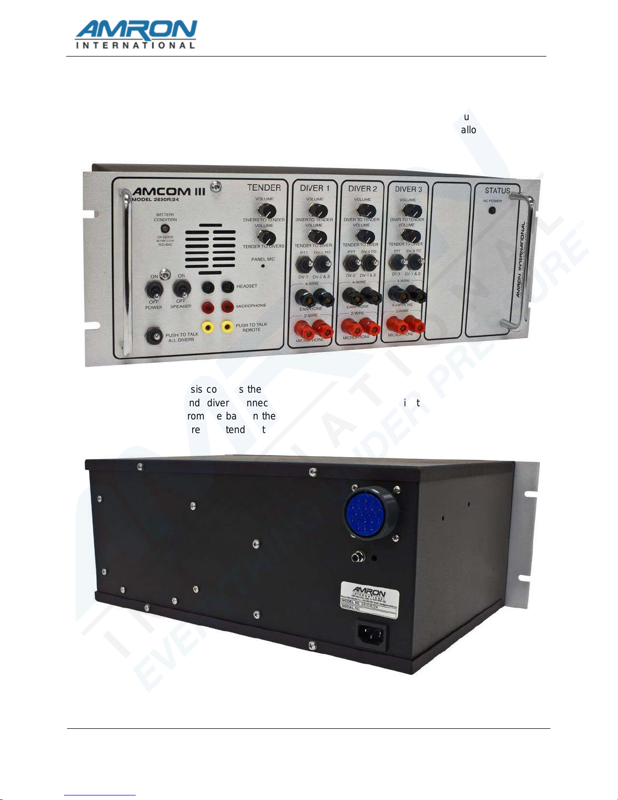
1.4 Amcom III Model 2830R/24 Diver Communicator.........................................................................2
2WARRANTY AND SERVICE POLICY .................................................................................................3
2.1 Limited Warranty...........................................................................................................................3
2.2 Service Policy................................................................................................................................3
3OPTIONS AND ACCESSORIES..........................................................................................................4
3.1 Options..........................................................................................................................................4
3.2 Accessories...................................................................................................................................4
4TENDER AND DIVER CONTROLS AND CONNECTIONS.................................................................7
4.1 Tender Controls ............................................................................................................................7
4.2 Tender Connections......................................................................................................................8
4.3 Diver Controls................................................................................................................................9
4.4 Diver Connections.........................................................................................................................9
4.5 Other Connections ......................................................................................................................10
4.6 Option Controls: Call Indicator –4002........................................................................................10
4.7 Option Controls: Helium Speech Unscrambler /26DSP3............................................................11
4.8 Option Controls: Wireless Tender /28A Option...........................................................................11
4.9 Drawing, 2-Wire Connections .....................................................................................................13
4.10 Drawing, Full Duplex (4-Wire) Connections................................................................................14
4.11 Drawing, Push-To-Talk Microphone Connections ......................................................................15
4.12 Drawing, Operator Connections, Headset ..................................................................................16
5INSTALLATION AND OPERATION...................................................................................................17
5.1 Operation.....................................................................................................................................17
5.2 AC Power....................................................................................................................................17
5.3 Modes Of Operation....................................................................................................................17
5.4 Volume Controls –2-Wire...........................................................................................................19
5.5 Other Diver Controls –2-Wire.....................................................................................................20
5.6 Volume Controls 4-Wire..............................................................................................................20
5.7 Other Tender Controls ................................................................................................................21
5.8 Options........................................................................................................................................22
6MAINTENANCE AND TROUBLESHOOTING...................................................................................24
6.1 Diver Radio Communicator Check Procedures ..........................................................................24
6.2 General Maintenance..................................................................................................................25
6.3 Recommended Maintenance Schedule......................................................................................26
6.4 Troubleshooting ..........................................................................................................................27
7FULL DUPLEX (4-WIRE) - WHAT, WHY AND HOW ........................................................................31
7.1 What Are 2-Wire And 4-Wire Modes?.........................................................................................31
7.2 What Is Full Duplex (4-Wire)?.....................................................................................................32
7.3 Why Full Duplex (4-Wire)?..........................................................................................................33
7.4 How Do You Use Full Duplex (4-Wire)? .....................................................................................33

2830R THREE DIVER COMMUNICATOR USER MANUAL
2830R-UM
REV 5.0
ii
8DRAWINGS ........................................................................................................................................35
8.1 Parts Identifier, Front Panel Model 2830R/24.............................................................................36
8.2 Parts Identifier, Options /26DSP3, /28A, -4002 ..........................................................................37
9PARTS LIST GENERAL.....................................................................................................................38
9.1 Amcom III Rackmount Model 2830R/24 .....................................................................................39
9.2 Amcom III Rack Mount, Unscrambler 2830R/24/26DSP3..........................................................39
9.3 Amcom III Model –4002 Option..................................................................................................39
9.4 Sub Assembly 2830R-400M, Front Panel Assembly..................................................................39
9.5 Sub Assembly 2830R/26-400M-DSP3, Front Panel Assembly ..................................................40
9.6 28XXR-FS-01 Spares Kit For 2830R/24.....................................................................................41
9.7 Optional Spares ..........................................................................................................................41

2830R THREE DIVER COMMUNICATOR USER MANUAL
2830R-UM
REV 5.0
1
1 INTRODUCTION AND SPECIFICATIONS
1.1 Introduction
The 2830R/24 AMCOM III Rack Mount Diver Communicator is a full featured, three-diver,
hardwire communicator that uses state-of-the-art electronics to provide clear and reliable
communications. The 2830R24 is designed for integration into a standard 19 inch equipment
rack and all necessary connections can be made via the front panel jack or rear mounted MS
connector.
For maximum safety and to enjoy all the features of the 2830R/24, it is important that the
tender read and understand the entire manual, including all warnings, before first use.
1.2 Electrical Specifications
Input Impedance (Microphone Inputs) ...................................................................... 250 Ohms
Frequency Response .......................................................................................300 –10,000 Hz
Common Mode Rejection (minimum) ................................................................................40 dB
Current Drain Maximum Full Volume .............................................................................3 Amps
Typical Quiescent .............................................................................250 mAmps
Minimum Load Impedance ............................................................................................ 2 Ohms
Input Voltage Range ..........................................................................................90 –264 VRMS
Input Voltage Frequency Range ..............................................................................47 –440 Hz
Nominal Power Supply Voltage ....................................................................................... 12 VDC
Operational Supply Voltage ........................................................................................9 - 18 VDC
Sensitivity (Input) .....................................................................................................1.6 mVRMS
Maximum Output Power (4 Ohm Load, 14 VDC) ...........................................................20 Watts
Battery Life (typical) ..................................................................................................... 10 Hours
1.3 Mechanical Specifications
Panel ........................................................................................ Anodized Brushed Aluminum
Enclosure ......................................................................................... Black Anodized Aluminum
DIMENSIONS
Length ...........................................................................................................12.5 in. (31.8 cm)
Width ...........................................................................................................19.0 in. (48.2 cm)
Height .............................................................................................................7.0 in. (17.7 cm)
WEIGHT WITH BATTERY
Weight with Battery........................................................................................19.5 Lbs. (8.85 kg)

2830R THREE DIVER COMMUNICATOR USER MANUAL
2830R-UM
REV 5.0
2
1.4 Amcom III Model 2830R/24 Diver Communicator
The front panel contains all the controls and connections required to operate the
communicator. It is intended that the divers will be connected to the communicator using the
rear chassis MS connector but the front panel 5-way binding post allows for ad-hoc
connections when required.
The rear chassis contains the AC power inlet, recorder output and an MS connector with all
the tender and diver connections. This allows a clean installation by routing all the
connections from the back in the rack. The rear tender connections allow for the installation
of a separate, remote tender station located away from the rack.

2830R THREE DIVER COMMUNICATOR USER MANUAL
2830R-UM
REV 5.0
3
2 WARRANTY AND SERVICE POLICY
2.1 Limited Warranty
AMRON INTERNATIONAL, INC., (Amron) warrants that its products are free from defects in
material and workmanship under normal use and service for a period of 90 days from date of
shipment as described in Amron literature covering this product. Amron’s obligation under
this warranty is limited to the repair of or replacement, at Amron’s option, of defective
material. This warranty shall not cover defects which are the result of misuse, negligence,
accident, repair or alterations.
2.2 Service Policy
For technical assistance or to request a repair, please call (760) 208-6500, Monday –Friday,
8 a.m. to 5 p.m. PT. Have the model number and serial number handy and be prepared to
offer as much information as possible about the problem.
Please do not return any product without obtaining a return authorization number. Detailed
instructions will be provided at the time of request.

2830R THREE DIVER COMMUNICATOR USER MANUAL
2830R-UM
REV 5.0
4
3 OPTIONS AND ACCESSORIES
The following options are available to customize the AMCOM communicator. Options have to be
ordered at the time of purchase or the communicator has to be returned to AMRON for the option to
be installed.
3.1 Options
3.1.1 Model /26DSP3 –Helium Speech Unscrambler
The AMRON’s DSP3 Helium Speech Unscrambler uses state of the art Digital
Signal Processor (DSP) technology to correct raw helium speech in clear,
intelligible voice. The /26DSP3 option includes a complex noise reduction filter to
improve communications in situations with high background noise levels.
3.1.2 Model /28A –Wireless Tender Option
The communicator is equipped with a wireless module and includes a Model 2829-
11 Wireless Tender Headset. The wireless headset allows the tender freedom to
move around. It requires the divers are wired in 4-Wire mode.
3.1.3 Model -4002 Chamber Call Lock Indicator
Chamber call lock indicator with annunciator.
3.2 Accessories
The following accessories are available for the AMCOM communicator. Accessories can be
ordered at any time.
3.2.1 Model 2401-28 –Amron Heavy-Duty Headset
The Model 2401-28 is a heavy-duty headset with boom microphone. It comes
equipped with color-coded, dual banana plugs that mate directly to AMCOM diver
communicators. It includes a 6-foot (1.8-meter) cord.
3.2.2 Model 2460-28 –Amron Standard Headset
The Model 2460-28 is a light and comfortable headset designed for extended wear
at an economical price. It comes equipped with color-coded, dual banana plugs
that mate directly to AMCOM diver communicators as well as a spiral cord that can
be extended up to 8 feet (2.4 meters).
3.2.3 Model 2405-28 –Amron Push-To-Talk Microphone
The Model 2405-28 is a hand-held, noise-canceling, push-to-talk microphone that
provides excellent sound quality to the diver. It comes equipped with a spiral cord
that can be extended up to 6 feet (1.8 meters).

2830R THREE DIVER COMMUNICATOR USER MANUAL
2830R-UM
REV 5.0
5
3.2.4 Model 2822-28 –Amron Remote Walk-And-Talk Module
Designed for Full Duplex (4-Wire) applications, the Model 2822-28 provides the
tender with mobility around the dive site while maintaining communications with the
diver. It comes equipped with a small clip-on belt module that contains the
connectors for the headset, and 25 feet (7.6 meters) of lightweight flexible cable.
Custom cable lengths are available.
3.2.5 Model 2821-28 –Amron Remote Push-To-Talk Module
Designed for 2-Wire applications, the Model 2821-28 provides the tender with
mobility around the dive site while maintaining communications with the diver. It
comes equipped with a small clip-on belt module that contains a push-to-talk
switch, connector for the headset, and 25 feet (7.6 meters) of lightweight flexible
cable. Custom cable lengths are available.
3.2.6 Model 2829-11 –Amron Wireless Tender Headset
A heavy-duty headset combined with a wireless belt module that is compatible with
the /28A option. One headset comes with communicators ordered with the /28A
options but additional headset can be ordered to allow other crew member to
monitor communications.
3.2.7 Model 3110 –Amron Chamber Speaker
The Model 3110 Chamber Speaker includes a push-to-talk switch along with a
headset connector. When the occupant(s) want to talk to the operator, the push-to-
talk switch on the chamber speaker must be pressed, even if the headset is in use.
3.2.8 Model 3115 –Amron Chamber Speaker
The Model 3115 Chamber Speaker allows the operator to monitor conversations
within the chamber with the speaker wired in 2-WIRE mode. There is a speaker
on/off switch that allows the occupants to turn off the speaker for private
conversations. The operator can talk to the occupant(s) by using the PUSH-TO-
TALK BUTTON or PUSH-TO-TALK JACK. The Model 3115 also features a
headset jack wired in Full-Duplex (4-Wire) mode that allows an occupant to use our
standard 2460-31R or deluxe 2401-31R headset to talk to the chamber operator
without the use of the PUSH-TO-TALK BUTTON or PUSH-TO-TALK JACK. This
speaker is approved for US Navy chambers.
3.2.9 Model 3113 –Amron Chamber Speaker
The Model 3113 Chamber Speaker has all the features of the Model 3115 except
for the speaker on/off switch.
3.2.10 Model 3125 –Amron Inner-Lock Combo Box
The Model 3125 features a talk-back speaker with on/off switch and headset jack
that operates in the same manner as the Model 3115. It also includes a sound-
powered phone with bracket, chamber temperature probe, scrubber power circuit

2830R THREE DIVER COMMUNICATOR USER MANUAL
2830R-UM
REV 5.0
6
wiring, chamber environmental conditioning unit wiring and electrical penetrator
adaptor all together in a single pre-wired, pre-tested housing.
3.2.11 Model 3126 –Amron Outer-Lock Combo Box
The Model 3126 features a talk-back speaker with on/off switch and headset jack
that operates in the same manner as the Model 3115. It also includes the sound-
powered phone and bracket like the Model 3125 but does not have the additional
chamber function wiring of the 3125.

2830R THREE DIVER COMMUNICATOR USER MANUAL
2830R-UM
REV 5.0
7
4 TENDER AND DIVER CONTROLS AND CONNECTIONS
Before using the 2830R/24 diver communicator, the tender should be familiar with all the operating
controls and connections. While reading this manual, you will find capitalized words such as PANEL
SPEAKER. These words are to remind the reader that additional information can be found in this
section of the manual.
4.1 Tender Controls
The following controls are located on the front panel of the 2830R/24 in the tender section.
4.1.1 Power Switch –This switch controls power to the unit.
4.1.2 Speaker Switch –This switch allows the tender to turn off the speaker. If the
tender is using a headset, it may be necessary to turn off the speaker in order to
prevent acoustic feedback.
4.1.3 Push-To-Talk All Divers Switch –This switch allows the tender to talk to all of
the divers when operating in the 2-Wire mode. It is not necessary to use this
control in the Full Duplex (4-Wire) mode. When using Full Duplex mode, this
control allows the tender to interrupt the diver by forcing the diver into listen only
mode.
4.1.4 Tender-To-Divers Volume –This control sets the volume for the divers’
earphone. Rotate this knob clockwise to increase the volume.
4.1.5 Diver To Tender Volume –This control sets the volume for the tender's
earphone and/or panel speaker. Rotate this knob clockwise to increase the volume.
4.1.6 Panel Speaker –A waterproof, acoustic horn speaker that allows the tender to
listen to the divers. The volume level is controlled by the EARPHONE VOLUME
control and it can be turned off using the SPEAKER SWITCH.
4.1.7 Battery Condition Indicator –A steady GREEN light indicates battery charge
level is good. Blinking GREEN light indicates battery charge level is at a low level
with less than 3 hours of running time available. Steady RED light indicates battery
charge level is below the level necessary to guarantee proper operation.
WARNING: When BATTERY CONDITION INDICATOR is steady RED light, the
batteries should be recharged immediately.
4.1.8 Panel Microphone –A water-resistant condenser microphone that allows the
tender to talk to the divers using the PUSH-TO-TALK BUTTONS. On the
2830R/24, the volume level is controlled by the MICROPHONE VOLUME control.
The PANEL MICROPHONE is muted when the SPEAKER SWITCH is turned off.
WARNING: Do not plug or cover the PANEL MICROPHONE hole. This may
dampen the tender-to-diver communications or damage the microphone
requiring replacement.

2830R THREE DIVER COMMUNICATOR USER MANUAL
2830R-UM
REV 5.0
8
4.2 Tender Connections
4.2.1 Tender Headset Jack –This is the dual banana jack (color-coded black) that
functions as both an output (earphone) and input (microphone) for the tender as
controlled by the PUSH-TO-TALK BUTTON and PUSH-TO-TALK JACK. Using this
connection, the tender can be wired in either 2-Wire or Full Duplex (4-Wire) mode
regardless of the mode used for the diver.
To connect the tender in the Full Duplex (4-Wire) mode, connect the earphone
(black) banana plug of the headset to this jack and the microphone (red) to the
TENDER MICROPHONE jack (red) as shown in the wiring diagram in section 4.10.
In this mode, the tender does not have to use the PUSH-TO-TALK BUTTON to
communicate with a diver who is also connected in the Full Duplex (4-Wire) mode.
This configuration can be used even if the diver is connected in 2-Wire mode. In
that situation, the tender is required to use the PUSH-TO-TALK BUTTON or
PUSH-TO-TALK JACK.
The headset microphone is always active, which means that there can be acoustic
feedback between the PANEL SPEAKER and the microphone if the tender is near
the communicator. To prevent this, the PANEL SPEAKER can be turned off using
the SPEAKER SWITCH. Another option is to move the tender away from the
communicator by using the Amron Model 2822-28 Walk-and-Talk Module
accessory. This allows the tender to communicate while other members of the
surface crew listen using the PANEL SPEAKER. This module comes with 25 feet
(7.6 meters) of cable (custom cable lengths are available).
The tender can also be connected in 2-Wire mode by stacking both the earphone
(black) and microphone (red) banana plugs into this jack as shown in the wiring
diagram in section 4.9. The diver does not have to be connected in 2-Wire mode if
the tender is in 2-Wire mode. In order to talk to the diver, the tender must use
either the PUSH-TO-TALK BUTTON or PUSH-TO-TALK JACK. Since the headset
microphone is not active until one of the push-to-talk methods is used, there is no
chance for acoustic feedback to occur and surface conversation or noise is not
transmitted to diver and the PANEL SPEAKER can be left on. This may, for some
situations, make for a better overall diving experience. If the tender requires more
mobility at the dive site, the Amron Model 2821-28 Remote Push-to-Talk Module
can be used to extend the headset cable. It includes a push-to-talk button on a clip-
on belt module and comes standard with 25 feet (7.6 meters) of cable (custom
cable lengths are available).
The tender may also use the optional Amron Model 2405-28 Push-to-Talk
Microphone. This microphone comes with two color-coded banana plugs. The
black plug goes into the TENDER HEADSET jack and the yellow plug goes in the
PUSH-TO-TALK JACK as shown in the wiring diagram in section 4.11. To
communicate with the diver, the tender presses the button on the side of the
microphone. There is no chance of acoustic feedback since the PANEL SPEAKER
is cut off when the tender uses the microphone. When using the Push-to-Talk
Microphone, the SPEAKER SWITCH must be turned on in order to hear the diver.

2830R THREE DIVER COMMUNICATOR USER MANUAL
2830R-UM
REV 5.0
9
4.2.2 Tender Microphone Jack –This is a dual banana jack (color-coded red) that
functions as the microphone input from the tender's headset. It is only used if the
tender is in Full Duplex (4-Wire) mode. On the 2830R/24, the TENDER
MICROPHONE VOLUME control adjusts the sensitivity of the input.
4.2.3 Push-To-Talk Jack –This is a dual banana jack (color-coded yellow) that allows
for remote keying of the push-to-talk function of the 2830R/24. The difference
between using the PUSH-TO-TALK JACK and PUSH-TO-TALK BUTTON is that
the button allows the tender to communicate using the PANEL MICROPHONE.
4.3 Diver Controls
The following controls are located on the front panel in the individual diver sections.
4.3.1 Diver Microphone Volume –The 2830R/24 has a separate microphone
volume control for each diver. This sets the gain for the diver’s microphone
amplifier and controls the diver’s volume level to the tender and other diver.
4.3.2 Diver Earphone Volume –The 2830R/24 has individual earphone volume
controls for each diver. This allows the tender to set the best volume level
for each diver.
4.3.3 Push To Talk Diver –There is a separate PUSH-TO-TALK momentary
switch for each diver. Normally used in 2-Wire mode, this control allows the
tender to talk to only one of the divers. The diver selected will hear both the
tender and the other divers. It can be used in Full Duplex (4-Wire) mode to
cut off the microphone of an individual diver.
4.3.4 Crosstalk –There is a separate CROSSTALK momentary switch for each
diver. Normally used in 2-Wire mode, this control allows the selected diver
to talk to the other divers while the tender monitors the conversation.
4.4 Diver Connections
4.4.1 Diver Microphone –This is a dual 5-way binding post jack (color-coded red) that
functions as both an output (earphone) and input (microphone) for the diver as
controlled by the PUSH-TO-TALK BUTTON and PUSH-TO-TALK JACK. Using this
connection, the diver can be wired in either 2-Wire or Full Duplex (4-Wire) mode
regardless of the mode used for the diver.
To connect the diver in Full Duplex (4-Wire) mode, connect the diver microphone to
this jack and the diver earphone the DIVER EARPHONE jack as shown in the
wiring diagram in section 4.9. The diver can use this mode even if the tender is
wired in 2-Wire mode.
To connect the diver in 2-Wire mode, connect both the diver microphone and
earphone to this jack. If the diver umbilical uses banana plugs, simply stack both
plugs into this jack as shown in the wiring diagram in section 4.8. In this mode, the
diver microphone will be active and heard on tender headset and/or PANEL

2830R THREE DIVER COMMUNICATOR USER MANUAL
2830R-UM
REV 5.0
10
SPEAKER unless the PUSH-TO-TALK BUTTON or PUSH-TO-TALK JACK is
activated.
4.4.2 Diver Earphone –This is a dual 5-way binding post jack (color-coded black) that
functions as the output for the diver's earphone. It is only used when the diver is in
Full Duplex (4-Wire) mode.
4.5 Other Connections
4.5.1 External Power Connector –The 2830R/24 uses a standard IEC C14 power
inlet located on the rear of the chassis. The communicator has a universal input
with a voltage range of 90-264 VRMS and a frequency range of 47-440 Hz. No
user adjustment is required.
4.5.2 Recorder Output –This is a single RCA Phono jack (color-coded black) located
on the rear of the chassis. It provides a transformer isolated signal of both the diver
and tender communications. It is designed to drive the standard line-level inputs of
audio or video recorders with input impedances as low as 600 Ohms.
4.5.3 MS Connector –A Military Series (MS) connector is located on the rear of the
chassis providing connections for both the Tender and Divers. This allows
connection without running wires to the front panel. The mating connector part
number is MS-3106A-28-16P. The pin functions are shown in the following table:
MS CONNECTOR PIN OUT IDENTIFICATIONS
PIN NUMBER
FUNCTION
A & B
DIVER 1 MICROPHONE
G & E
DIVER 1 EARPHONE
L & M
DIVER 2 MICROPHONE
H & F
DIVER 2 HEADPHONE
S & K
DIVER 3 MICROPHONE
U & V
DIVER 3 EARPHONE
J & T
TENDER MICROPHONE
Q & P
TENDER EARPHONE
D & N
RECORDER OUTPUT
R
PUSH-TO-TALK
C
COMMON
4.6 Option Controls: Call Indicator –4002
The call indicator lights are located in the STATUS panel on the far right side of the front
panel. This option can be purchased with HSU and Wireless Tender Options.
4.6.1 Lock Indicator –LED Lamp indicates a call originating from a lock. Lamps are
provided for each lock.
4.6.2 Call Annunciator –Alerts the operator of a call.

2830R THREE DIVER COMMUNICATOR USER MANUAL
2830R-UM
REV 5.0
11
4.7 Option Controls: Helium Speech Unscrambler /26DSP3
The controls for the DSP3 Helium Speech Unscrambler (HSU) are located in the section
immediately right of the DIVER 3 controls on the front panel.
4.7.1 On/Off Switch –Allows the selection of air (OFF) or helium (ON) operation. In
the OFF position, the divers’ microphone signal bypasses the HSU. In the ON
position, the microphone signals are routed to the HSU and the tender can adjust
the controls as necessary.
4.7.2 Treble Boost –Selects the amount of gain added to the High Frequency (HF)
portion of the divers’ microphone signals. This compensates for the HF drop-off in
the sensitivity of most microphones. The TREBLE BOOST feature allows for
optimum frequency enhancement and improved intelligible speech from the diver’s
voice.
4.7.3 Depth Control –Selects the amount of frequency correction performed by the
HSU to produce intelligible speech. This control uses a multi-turn potentiometer
and is equipped with a turn counting knob and lock. Once the desired setting is
reached, the lock can be used to prevent accidental changes to this control.
4.7.4 Noise Reduction Filter –The Noise Reduction Filter (NRF) uses a complex
Digital Signal Processor algorithm based on a statistical-model of human voice
activity to capture the background noise and reduce it without affecting the divers’
speech. The noise level can be reduced by up to 17 dB.
4.8 Option Controls: Wireless Tender /28A Option
The controls for the Wireless Tender Option are located in the section immediately right of the
DIVER 3 controls on the front panel. The Wireless Tender Option is for four-wire (Full Duplex)
operation only. System comes standard with a remote wireless tender module.
4.8.1 Wireless Option Panel –Comes standard with antenna and power on/off
switch. The “ON/OFF” switch powers the wireless PC card inside the
communicator. The antenna has a swivel and tilt that allows the antenna to be
folded down during shipment. For operation, the antenna should be pointing
upwards. For installations where the Diver Communicator is located inside a
structure, there is an optional Remote Antenna kit available. This kit allows the
antenna to be located outside the structure for maximum effective range.
IMPORTANT: When the wireless option is not used, turn the option panel switch to
“OFF”. When option panel switch is turned “ON”, the wireless remote should be
“ON”. Otherwise a static noise may be heard through the communicator’s panel
speaker as it scans for available Remote Wireless Tender.
4.8.2 Remote Wireless Tender Module –This module comes standard with an
internal rechargeable battery. Headset and external 110V charger jacks are located
on remote module.

2830R THREE DIVER COMMUNICATOR USER MANUAL
2830R-UM
REV 5.0
12
4.8.3 On/Off-Volume Control –Adjusts the listening volume and turns the unit “OFF”
when it is turned completely upwards.
4.8.4 Talk Push Button –This button is located on the top of the unit and is labeled
TALK. When it’s first turned on, the Remote Wireless Tender Module is in Standby
Mode (listen only) as indicated by the LED closest to the button being red. When
the button is pressed, the Remote Wireless Tender Module is in “Talk Mode” (listen
and talk, full duplex) and the LED is green. Pressing the TALK button toggles
between the two modes. Multiple Remote Wireless Tender Modules can be in the
Standby (listen only) mode at the same time. Only one module can be in the talk
mode.
4.8.5 Headset Jack –Located on the side opposite the ON/OFF-Volume Control. Plug
the remote wireless headset to this jack.
4.8.6 Charge Jack –Located on the side next to the ON/OFF-Volume Control. Plug the
remote wireless charger to this jack.

2830R THREE DIVER COMMUNICATOR USER MANUAL
2830R-UM
REV 5.0
13
4.9 Drawing, 2-Wire Connections

2830R THREE DIVER COMMUNICATOR USER MANUAL
2830R-UM
REV 5.0
14
4.10 Drawing, Full Duplex (4-Wire) Connections

2830R THREE DIVER COMMUNICATOR USER MANUAL
2830R-UM
REV 5.0
15
4.11 Drawing, Push-To-Talk Microphone Connections

2830R THREE DIVER COMMUNICATOR USER MANUAL
2830R-UM
REV 5.0
16
4.12 Drawing, Operator Connections, Headset
Table of contents
Other Amron Cell Phone manuals

Amron
Amron 2810E-2001 User manual

Amron
Amron 2820A-02 User manual

Amron
Amron 2810E-ATEX User manual

Amron
Amron 2830A Series User manual

Amron
Amron AMCON II 2825R Series User manual

Amron
Amron 2810A-2001 User manual

Amron
Amron 2820A User manual

Amron
Amron 2820A-4003 User manual

Amron
Amron 2810E User manual

Amron
Amron Amcom II 2825R/24 Series User manual