Amron AMCON II 2825R Series User manual

User Manual
For
Amron International, Inc.
Model 2825R-XX Series
Two Diver Rack Mount Communicators
S/N ____________________
1380 Aspen Way, Vista California 92081-8349
United States of America
Phone: (760) 208-6500
Fax (760) 599-3857
Email: sales@amronintl.com
Web: www.amronintl.com
This manual and the information contained herein are provided for use as an operation and maintenance
guide. No license or rights to manufacture, reproduce, or sell either the manual or articles described
herein are given. Amron International, Inc. reserves the right to change specifications without notice.
Copyright© 2018 Amron International, Inc.


2825R-XX SERIES TWO DIVER RACK
MOUNT COMMUNICATOR USER MANUAL
282XR-UM
REV 5.0
i
TABLE OF CONTENTS
1INTRODUCTION AND SPECIFICATIONS ..........................................................................................1
1.1 Introductions..................................................................................................................................1
1.2 Electrical Specifications ................................................................................................................1
1.3 Mechanical Specifications.............................................................................................................1
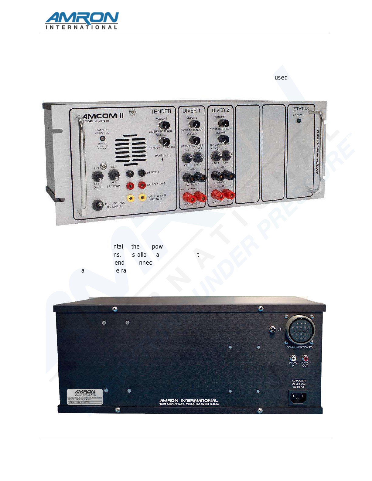
1.4 Amcom II Model 2825R-XX Two Diver Rack Mount Communicator ............................................2
2OPTIONS AND ACCESSORIES..........................................................................................................3
2.1 Options..........................................................................................................................................3
2.2 Accessories...................................................................................................................................3
3CONTROLS AND CONNECTIONS......................................................................................................5
3.1 Tender Controls ............................................................................................................................5
3.2 Tender Connections......................................................................................................................6
3.3 Diver Controls................................................................................................................................7
3.4 Diver Connections.........................................................................................................................7
3.5 Other Connections ........................................................................................................................8
3.6 Option Controls: DSP3 Helium Speech Unscrambler...................................................................9
3.7 Drawing, 2-Wire Connections .....................................................................................................10
3.8 Drawing, Full Duplex (4-Wire) Connections................................................................................11
3.9 Drawing, Push To Talk Microphone Connections.......................................................................12
3.10 Drawing, Operator Connections, Headset ..................................................................................13
4INSTALLATION AND OPERATION...................................................................................................14
4.1 Operation.....................................................................................................................................14
4.2 AC Power....................................................................................................................................14
4.3 Modes Of Operation....................................................................................................................14
4.4 Volume Controls (2-Wire)............................................................................................................16
4.5 Other Diver Controls (2-Wire) .....................................................................................................16
4.6 Volume Controls (4-Wire)............................................................................................................17
4.7 Other Tender Controls ................................................................................................................18
4.8 Options........................................................................................................................................19
5MAINTENANCE AND TROUBLESHOOTING...................................................................................20
5.1 Diver Radio Communicator Check Procedures ..........................................................................20
5.2 General Maintenance..................................................................................................................21
5.3 Recommended Maintenance Schedule......................................................................................22
5.4 Troubleshooting ..........................................................................................................................23
6DRAWINGS ........................................................................................................................................26
6.1 Parts Identifier, Front Panel, Model 2825R-01............................................................................27
6.2 Parts Identifier, Front Panel, Model 2825R-02............................................................................28
PARTS LIST .......................................................................................................................................2977.1 Amcom II Rack Mount, Model 2825R-01....................................................................................30
7.2 Amcom II Rack Mount with DSP3 Helium Speech Unscrambler, Model 2825R-02...................30
7.3 Sub Assembly 2825R-400M, Front Panel Components.............................................................30
7.4 Sub Assembly 2825R/26-400M-DSP3, Front Panel Components .............................................31
7.5 28XXR-FS-02 Spares Kit For 2825R-XX Series Communicators ..............................................31
7.6 Optional Spares ..........................................................................................................................32
8LIMITED WARRANTY AND SERVICE POLICY................................................................................33

2825R-XX SERIES TWO DIVER RACK
MOUNT COMMUNICATOR USER MANUAL
282XR-UM
REV 5.0
1
1 INTRODUCTION AND SPECIFICATIONS
1.1 Introductions
The 2825R-XX Series AMCOM II Rack Mount Diver Communicators are a full featured, two-
diver, hardwire communicator that uses state-of-the-art electronics to provide clear and
reliable communications. The 2825R-XX is designed for integration into a standard 19 inch
equipment rack and all necessary connections can be made via the front panel jack or rear
mounted MS connector.
For maximum safety and to enjoy all the features of the 2825R-XX, it is important that the
tender read and understand the entire manual, including all warnings, before first use.
1.2 Electrical Specifications
Input Impedance (Each Input) ................................................................................... 250 Ohms
Frequency Response ........................................................................................ 300 - 10000 Hz
Common Mode Rejection ..................................................................................40 dB Minimum
Current Drain Maximum Full Volume .............................................................................3 Amps
Minimum Quiescent ................................................................................................ 0.190 Amps
Output Impedance ........................................................................................................... 4 Ohm
Power Supply Voltage ..............................................12 VDC Nominal (9 VDC Min - 16 VDC Max)
AC Power Operating Range .................................................................... 90-264 VAC, 50-60 Hz
Sensitivity (Input) .............................................................................................................0.5 mV
Output Power (RMS @ 4 Ohm Load, 12 VDC) ..................................................10 Watts Audio
Battery Life (typical) ..................................................................................................... 45 Hours
1.3 Mechanical Specifications
Panel ....................................................................................... Anodized Brushed Aluminum
Enclosure ..........................................................................................Black Anodized Aluminum
DIMENSIONS
Length ..........................................................................................................12.5 In. (31.8 Cm)
Width ..........................................................................................................19.0 In. (48.2 Cm)
Height ............................................................................................................7.0 In. (17.7 Cm)
Weight with battery ........................................................................................ 19.5 Lbs. (8.8 Kg)

2825R-XX SERIES TWO DIVER RACK
MOUNT COMMUNICATOR USER MANUAL
282XR-UM
REV 5.0
2
1.4 Amcom II Model 2825R-XX Two Diver Rack Mount Communicator
The front panel contains all the controls and connections required to operate the
communicator. It is intended that the divers will be connected to the communicator using the
rear chassis MS connector, but the front panel 5-way binding post can be used as required.
The rear chassis contains the AC power inlet, recorder output and an MS connector with all the tender
and diver connections. This allows a clean installation by routing all the connections from the back in
the rack. The rear tender connections allow for the installation of a separate, remote tender station
located away from the rack.

2825R-XX SERIES TWO DIVER RACK
MOUNT COMMUNICATOR USER MANUAL
282XR-UM
REV 5.0
3
2 OPTIONS AND ACCESSORIES
2.1 Options
The following options are available to customize the AMCOM communicator. Options have to
be ordered at the time of purchase or the communicator has to be returned to AMRON for the
option to be installed.
2.1.1 Model 2825R-02 With DSP3 Helium Speech Unscrambler
The AMRON’s DSP3 Helium Speech Unscrambler uses state of the art Digital
Signal Processor (DSP) technology to correct raw helium speech in clear,
intelligible voice. The HSU option includes a complex noise reduction filter to
improve communications in situations with high background noise levels.
2.2 Accessories
The following accessories are available for the AMCOM communicator. Accessories can be
ordered at any time.
2.2.1 Model 2401-28 –Amron Heavy-Duty Headset
The Model 2401-28 is a heavy-duty headset with boom microphone. It comes
equipped with color-coded, dual banana plugs that mate directly to AMCOM diver
communicators. It includes a 6-foot (1.8-meter) cord.
2.2.2 Model 2460-28 –Amron Standard Headset
The Model 2460-28 is a light and comfortable headset designed for extended wear
at an economical price. It comes equipped with color-coded, dual banana plugs
that mate directly to AMCOM diver communicators as well as a spiral cord that can
be extended up to 8 feet (2.4 meters).
2.2.3 Model 2405-28 –Amron Push-To-Talk Microphone
The Model 2405-28 is a hand-held, noise-canceling, push-to-talk microphone that
provides excellent sound quality to the diver. It comes equipped with a spiral cord
that can be extended up to 6 feet (1.8 meters).
2.2.4 Model 2822-28 –Amron Remote Walk-And-Talk Module
Designed for Full Duplex (4-Wire) applications, the Model 2822-28 provides the
tender with mobility around the dive site while maintaining communications with the
diver. It comes equipped with a small clip-on belt module that contains the
connectors for the headset, and 25 feet (7.6 meters) of lightweight flexible cable.
Custom cable lengths are available.

2825R-XX SERIES TWO DIVER RACK
MOUNT COMMUNICATOR USER MANUAL
282XR-UM
REV 5.0
4
2.2.5 Model 2821-28 –Amron Remote Push to Talk Module
Designed for 2-Wire applications, the Model 2821-28 provides the tender with
mobility around the dive site while maintaining communications with the diver. It
comes equipped with a small clip-on belt module that contains a push-to-talk
switch, connector for the headset, and 25 feet (7.6 meters) of lightweight flexible
cable. Custom cable lengths are available.
2.2.6 Model 3110 –Amron Chamber Speaker
The Model 3110 Chamber Speaker includes a push-to-talk switch along with a
headset connector. When the occupant(s) want to talk to the operator, the push-to-
talk switch on the chamber speaker must be pressed, even if the headset is in use.
2.2.7 Model 3115 –Amron Chamber Speaker
The Model 3115 Chamber Speaker allows the operator to monitor conversations
within the chamber with the speaker wired in 2-WIRE mode. There is a speaker
on/off switch that allows the occupants to turn off the speaker for private
conversations. The operator can talk to the occupant(s) by using the PUSH-TO-
TALK BUTTON or PUSH-TO-TALK JACK. The Model 3115 also features a
headset jack wired in Full-Duplex (4-Wire) mode that allows an occupant to use our
standard 2460-31R or deluxe 2401-31R headset to talk to the chamber operator
without the use of the PUSH-TO-TALK BUTTON or PUSH-TO-TALK JACK. This
speaker is approved for US Navy chambers.
2.2.8 Model 3113 –Amron Chamber Speaker
The Model 3113 Chamber Speaker has all the features of the Model 3115 except
for the speaker on/off switch.
2.2.9 Model 3125 –Amron Inner-Lock Combo Box
The Model 3125 features a talk-back speaker with on/off switch and headset jack
that operates in the same manner as the Model 3115. It also includes a sound-
powered phone with bracket, chamber temperature probe, scrubber power circuit
wiring, chamber environmental conditioning unit wiring and electrical penetrator
adaptor all together in a single pre-wired, pre-tested housing.
2.2.10 Model 3126 –Amron Outer-Lock Combo Box
The Model 3126 features a talk-back speaker with on/off switch and headset jack
that operates in the same manner as the Model 3115. It also includes the sound-
powered phone and bracket like the Model 3125 but does not have the additional
chamber function wiring of the 3125.

2825R-XX SERIES TWO DIVER RACK
MOUNT COMMUNICATOR USER MANUAL
282XR-UM
REV 5.0
5
3 CONTROLS AND CONNECTIONS
Before using the 2825R-XX diver communicator, the tender should be familiar with all the operating
controls and connections. While reading this manual, you will find capitalized words such as PANEL
SPEAKER. These words are to remind the reader that additional information can be found in this
section of the manual.
3.1 Tender Controls
The following controls are located on the front panel of the 2825R-XX/24 in the tender
section.
3.1.1 Power Switch –This switch controls power to the unit.
3.1.2 Speaker Switch –This switch allows the tender to turn off the speaker. If the
tender is using a headset, it may be necessary to turn off the speaker in order to
prevent acoustic feedback.
3.1.3 Push-To-Talk All Divers Switch –This switch allows the tender to talk to all
divers when operating in the 2-Wire mode. It is not necessary to use this control in
the Full Duplex (4-Wire) mode. When using Full Duplex mode, this control allows
the tender to interrupt the diver by forcing the diver into listen only mode.
3.1.4 Tender-To-Divers Volume –This control sets the volume for the divers’ earphone.
Rotate this knob clockwise to increase the volume.
3.1.5 Diver To Tender Volume –This control sets the volume for the tender's earphone
and/or panel speaker. Rotate this knob clockwise to increase the volume.
3.1.6 Panel Speaker –A waterproof, acoustic horn speaker that allows the tender to
listen to the divers. The volume level is controlled by the EARPHONE VOLUME
control and it can be turned off using the SPEAKER SWITCH.
3.1.7 Battery Condition Indicator –A steady GREEN light indicates battery charge
level is good. Blinking GREEN light indicates battery charge level is at a low level
with less than 3 hours of running time available. Steady RED light indicates battery
charge level is below the level necessary to guarantee proper operation.
WARNING: When BATTERY CONDITION INDICATOR is steady RED light, the
battery should be recharged immediately.
3.1.8 Panel Microphone –A water-resistant condenser microphone that allows the
tender to talk to the divers using the PUSH-TO-TALK BUTTONS. On the 2825R-
XX, the volume level is controlled by the MICROPHONE VOLUME control. The
PANEL MICROPHONE is muted when the SPEAKER SWITCH is turned off.
WARNING: Do not plug or cover the PANEL MICROPHONE hole. This may
dampen the tender-to-diver communications or damage the microphone
requiring replacement.

2825R-XX SERIES TWO DIVER RACK
MOUNT COMMUNICATOR USER MANUAL
282XR-UM
REV 5.0
6
3.2 Tender Connections
3.2.1 Tender Headset Jack –This is the dual banana jack (color-coded black) that
functions as both an output (earphone) and input (microphone) for the tender as
controlled by the PUSH-TO-TALK BUTTON and PUSH-TO-TALK JACK. Using this
connection, the tender can be wired in either 2-Wire or Full Duplex (4-Wire) mode
regardless of the mode used for the diver.
To connect the tender in the Full Duplex (4-Wire) mode, connect the earphone
(black) banana plug of the headset to this jack and the microphone (red) to the
TENDER MICROPHONE jack (red) as shown in the wiring diagram in section 4.10.
In this mode, the tender does not have to use the PUSH-TO-TALK BUTTON to
communicate with a diver who is also connected in the Full Duplex (4-Wire) mode.
This configuration can be used even if the diver is connected in 2-Wire mode. In
that situation, the tender is required to use the PUSH-TO-TALK BUTTON or
PUSH-TO-TALK JACK.
The headset microphone is always active, which means that there can be acoustic
feedback between the PANEL SPEAKER and the microphone if the tender is near
the communicator. To prevent this, the PANEL SPEAKER can be turned off using
the SPEAKER SWITCH. Another option is to move the tender away from the
communicator by using the Amron Model 2822-28 Walk-and-Talk Module
accessory. This allows the tender to communicate while other members of the
surface crew listen using the PANEL SPEAKER. This module comes with 25 feet
(7.6 meters) of cable (custom cable lengths are available).
The tender can also be connected in 2-Wire mode by stacking both the earphone
(black) and microphone (red) banana plugs into this jack as shown in the wiring
diagram in section 4.9. The diver does not have to be connected in 2-Wire mode if
the tender is in 2-Wire mode. In order to talk to the diver, the tender must use
either the PUSH-TO-TALK BUTTON or PUSH-TO-TALK JACK. Since the headset
microphone is not active until one of the push-to-talk methods is used, there is no
chance for acoustic feedback to occur and surface conversation or noise is not
transmitted to diver and the PANEL SPEAKER can be left on. This may, for some
situations, make for a better overall diving experience. If the tender requires more
mobility at the dive site, the Amron Model 2821-28 Remote Push-to-Talk Module
can be used to extend the headset cable. It includes a push-to-talk button on a clip-
on belt module and comes standard with 25 feet (7.6 meters) of cable (custom
cable lengths are available).
The tender may also use the optional Amron Model 2405-28 Push-to-Talk
Microphone. This microphone comes with two color-coded banana plugs. The
black plug goes into the TENDER HEADSET jack and the yellow plug goes in the
PUSH-TO-TALK JACK as shown in the wiring diagram in section 4.11. To
communicate with the diver, the tender presses the button on the side of the
microphone. There is no chance of acoustic feedback since the PANEL SPEAKER
is cut off when the tender uses the microphone. When using the Push-to-Talk
Microphone, the SPEAKER SWITCH must be turned on in order to hear the diver.

2825R-XX SERIES TWO DIVER RACK
MOUNT COMMUNICATOR USER MANUAL
282XR-UM
REV 5.0
7
3.2.2 Tender Microphone Jack –This is a dual banana jack (color-coded red) that
functions as the microphone input from the tender's headset. It is only used if the
tender is in Full Duplex (4-Wire) mode. On the 2825R-XX, the TENDER
MICROPHONE VOLUME control adjusts the sensitivity of the input.
3.2.3 Push-To-Talk Jack –This is a dual banana jack (color-coded yellow) that allows
for remote keying of the push-to-talk function of the 2825R-XX. The difference
between using the PUSH-TO-TALK JACK and PUSH-TO-TALK BUTTON is that
the button allows the tender to communicate using the PANEL MICROPHONE.
3.3 Diver Controls
The following controls are located on the front panel in the individual diver sections.
3.3.1 Diver Microphone Volume –The 2825R-XX has a separate microphone volume
control for each diver. This sets the gain for the diver’s microphone amplifier and
controls the diver’s volume level to the tender and other diver.
3.3.2 Diver Earphone Volume –The 2825R-XX has individual earphone volume
controls for each diver. This allows the tender to set the best volume level for each
diver.
3.3.3 Diver On/Off –There is a separate DIVER ON/OFF momentary switch for each
diver. This control allows the tender to temporarily cut off the microphone of an
individual diver. It can be used in 2-Wire or Full Duplex (4-Wire) modes.
3.3.4 Crosstalk –There is a separate CROSSTALK momentary switch for each diver.
Normally used in 2-Wire mode, this control allows the selected diver to talk to the
other diver while the tender monitors the conversation.
3.4 Diver Connections
3.4.1 Diver Microphone - This is a dual 5-way binding post jack (color-coded red) that
functions as both an output (earphone) and input (microphone) for the diver as
controlled by the PUSH-TO-TALK BUTTON and PUSH-TO-TALK JACK. Using this
connection, the diver can be wired in either 2-Wire or Full Duplex (4-Wire) mode
regardless of the mode used for the diver.
To connect the diver in Full Duplex (4-Wire) mode, connect the diver microphone to
this jack and the diver earphone the DIVER EARPHONE jack as shown in the
wiring diagram in section 4.9. The diver can use this mode even if the tender is
wired in 2-Wire mode.
To connect the diver in 2-Wire mode, connect both the diver microphone and
earphone to this jack. If the diver umbilical uses banana plugs, simply stack both
plugs into this jack as shown in the wiring diagram in section 4.8. In this mode, the
diver microphone will be active and heard on tender headset and/or PANEL
SPEAKER unless the PUSH-TO-TALK BUTTON or PUSH-TO-TALK JACK is
activated.

2825R-XX SERIES TWO DIVER RACK
MOUNT COMMUNICATOR USER MANUAL
282XR-UM
REV 5.0
8
3.4.2 Diver Earphone - This is a dual 5-way binding post jack (color-coded black) that
functions as the output for the diver's earphone. It is only used when the diver is in
Full Duplex (4-Wire) mode.
3.5 Other Connections
3.5.1 External Power Inlet - The 2830R-XX uses a standard IEC C14 power inlet
located on the rear of the chassis. The communicator has a universal input with a
voltage range of 90-264 VRMS and a frequency range of 50-60 Hz. No user
adjustment is required.
Audio In - This is a single RCA jack (color-coded Red) located on the rear of the
3.5.2 chassis receives a standard audio line-level signal from another device. The audio
mixer outputs this signal to the tender and divers. AUDIO IN may be connected to
AUDIO OUT of another AMCOM rack mount communicator for double redundancy
requirements or can double the number of users. It may also be connected to
playback devices, a cell phone, a wireless tender device, etc.
3.5.3 Audio Out - This is a single RCA jack (color-coded White) located on the rear of
the chassis and sends a standard audio line-level signal to another device. The
audio mixer outputs this signal to the tender and divers. AUDIO OUT may be
connected to AUDIO IN of another AMCOM rack mount communicator for double
redundancy requirements or can double the number of users. It may also be
connected to recorder devices, a cell phone, a wireless tender device, etc.
3.5.4 Recorder Output - This is a single RCA jack (color-coded black) located on the
rear of the chassis. It provides a transformer isolated signal of both the diver and
tender communications. It is designed to drive the standard line-level inputs of
audio or video recorders with input impedances as low as 600 Ohms.
3.5.5 MS Connector - A Military Series (MS) connector is located on the rear of the
chassis providing connections for both the Tender and Divers. This allows
connection without running wires to the front panel. The mating connector part
number is MS-3106A-28-16P. The pin functions are shown in the following table:
MS connector Pin Out Identifications
Pin Number
Function
A & B
Diver 1 Microphone
E & G
Diver 1 Earphone
L & M
Diver 2 Microphone
F & H
Diver 2 Headphone
J & T
Tender Microphone
P & Q
Tender Earphone
D & N
Recorder Output
C
Push-to-Talk (Low)
R
Push-to-Talk (High)
N
Audio Out (Low)
D
Audio Out (High)

2825R-XX SERIES TWO DIVER RACK
MOUNT COMMUNICATOR USER MANUAL
282XR-UM
REV 5.0
9
3.6 Option Controls: DSP3 Helium Speech Unscrambler
The controls for the DSP3 Helium Speech Unscrambler (HSU) are located in the section
immediately right of the DIVER 2 controls on the front panel.
3.6.1 On/Off Switch –Allows the selection of air (OFF) or helium (ON) operation. In the
OFF position, the divers’ microphone signal bypasses the HSU. In the ON position,
the microphone signals are routed to the HSU and the tender can adjust the
controls as necessary.
3.6.2 Treble Boost –Selects the amount of gain added to the High Frequency (HF)
portion of the divers’ microphone signals. This compensates for the HF drop-off in
the sensitivity of most microphones. The TREBLE BOOST feature allows for
optimum frequency enhancement and improved intelligible speech from the diver’s
voice.
3.6.3 Depth Control –Selects the amount of frequency correction performed by the
HSU to produce intelligible speech. This control uses a multi-turn potentiometer
and is equipped with a turn counting knob and lock. Once the desired setting is
reached, the lock can be used to prevent accidental changes to this control.
3.6.4 Noise Reduction Filter –The Noise Reduction Filter (NRF) uses a complex Digital
Signal Processor algorithm based on a statistical-model of human voice activity to
capture the background noise and reduce it without affecting the divers’ speech.
The noise level can be reduced by up to 17 dB.

2825R-XX SERIES TWO DIVER RACK
MOUNT COMMUNICATOR USER MANUAL
282XR-UM
REV 5.0
10
3.7 Drawing, 2-Wire Connections

2825R-XX SERIES TWO DIVER RACK
MOUNT COMMUNICATOR USER MANUAL
282XR-UM
REV 5.0
11
3.8 Drawing, Full Duplex (4-Wire) Connections

2825R-XX SERIES TWO DIVER RACK
MOUNT COMMUNICATOR USER MANUAL
282XR-UM
REV 5.0
12
3.9 Drawing, Push To Talk Microphone Connections

2825R-XX SERIES TWO DIVER RACK
MOUNT COMMUNICATOR USER MANUAL
282XR-UM
REV 5.0
13
3.10 Drawing, Operator Connections, Headset

2825R-XX SERIES TWO DIVER RACK
MOUNT COMMUNICATOR USER MANUAL
282XR-UM
REV 5.0
14
4 INSTALLATION AND OPERATION
4.1 Operation
The 2825R-XX Series AMCOM II rack mount diver communicator is designed to mount in a
standard electronic equipment rack, 19 inches wide. The unit has connections located on
both the front and rear of the enclosure, to facilitate system wiring. For system installation all
connections can be made to the rear of the unit, eliminating wires hanging from the front
panel.
The AMCOM II panels are graphically divided into sections; Tender Controls, Diver Controls,
and Options. Items within these areas are functions or controls relating to the Tender,
Diver(s) or Optional items.
4.2 AC Power
When the unit is connected to AC power the LED power indicator on the STATUS section of
the front panel will illuminate, confirming the presence of AC power.
The AMCOM II is designed to operate from AC voltage (90-264 VRMS 50-60 Hz) with a 12
VDC gel cell battery for backup operation in the event of loss of AC power. The switch over to
battery operation is completely automatic, and occurs whenever AC power is interrupted. The
internal rechargeable battery is maintained at full charge while the unit is operating from AC
power. AC power indicator on the optional panel confirms the presence of AC power.
CAUTION: ALWAYS exercise extreme caution when operating AC powered equipment,
especially when outdoors, where conditions are damp or wet, or when around other
equipment. Never operate unit without earth-ground or without a working ground fault
interrupter. When in doubt discontinue use immediately and have a qualified electrician
inspect your equipment before using.
WARNING: All AC powered equipment should be used with a ground fault interrupter.
All ground fault interrupters have a built in test circuit, check for proper operation
before using.
NOTE: Do not continue to operate rechargeable battery below the low battery condition or
permanent damage will occur. When the battery condition indicator turns to red color, shut
unit off and charge battery.
4.3 Modes Of Operation
The 2825R-XX Series communicator has the ability to operate in either 2-Wire or Full Duplex
(4-Wire). Both the diver and tender can be connected in either mode and a combination of
modes can be used. If either the diver or the tender is wired in 2-Wire mode, the tender must
use a push-to-talk, either the PUSH-TO-TALK ALL SWITCH or PUSH-TO-TALK JACK, when
talking to the diver.
2-Wire communication is defined as a single communication path, normally the diver is the
priority signal path –tender listens to diver. Signal reversing is accomplished by pushing the
PUSH-TO-TALK BUTTON –diver hears tender. Often times a 4-conductor communication
cable is used with two wires tied together as a pair for redundancy, this is still a 2-Wire

2825R-XX SERIES TWO DIVER RACK
MOUNT COMMUNICATOR USER MANUAL
282XR-UM
REV 5.0
15
system. Since only one person can talk at a time, there is a level of discipline that goes with
using 2-Wire mode in order to obtain clear communication. One advantage of 2-Wire is that
the tender's microphone is not active unless one of the two push-to-talk controls, PUSH-TO-
TALK BUTTON or PUSH-TO-TALK JACK, are active. This eliminates any possible acoustic
feedback between the tender's microphone and the PANEL SPEAKER. It also prevents noise
from the surface reaching the diver and allows the tender to communicate with other
members of the surface crew without involving the diver.
Full Duplex (4-Wire) communication is defined as a dual communication path, a signal path
(a pair of wires) for up-link and a signal path (a pair of wires) for down link. A common
example of Full Duplex communication is the telephone. Full Duplex (4-Wire) has the
advantage of natural communication without having to use the PUSH-TO-TALK BUTTON.
This keeps the tender's hands free to perform other task. It does not require the same level of
discipline to achieve clear communications that 2-Wire does. It has the advantage that
neither the diver nor the tender are cut off when the other is talking. Because the diver's
microphone is not connected in parallel with the earphone, the diver is louder and potentially
clearer in Full Duplex (4-Wire) mode.
4.3.1 2-Wire Operation
To connect the diver in 2-Wire mode, connect the communication umbilical wires to
the DIVER MICROPHONE binding post jack on the communicator as shown in the
wiring drawing in section 3.7. If the umbilical uses a banana plug, simply insert the
plug into the binding post jack. Verify that it is firmly and completely seated. This
may require that the external plastic nut be tightened down. If the umbilical uses
bare wires, loosen the external plastic nut of the binding post jack. Either insert the
bare end of the wire into the hole in the metal shaft of the binding post or firmly
wrap the wire around the shaft. Tighten the nut until the bare wire is firmly fastened
by the nut. The nut should not be fastened on the insulation of the wire nor should
any of the bare wires touch.
The earphone connection is not used by the divers. The earphone jacks can be
used to operate a remote speaker. Both diver and tender conversations will be
heard.
When the tender uses a headset or push-to-talk microphone, follow the connection
instruction in section 3.2.1 and in the wiring diagram in sections 3.9 and 3.10.
When using the Amron Model 2821-28 Push-to-Talk Microphone, the tender
presses the push-to-talk button on the side of the microphone and speaks clearly at
a distance of between 1 and 2 inches (25 to 51 mm). When done speaking, the
tender releases the push-to-talk button to allow the diver to communicate.
In 2-wire mode the tender must press the Push-to-talk Switch to be heard. If you
are using the Amron Remote Push-to-Talk, Model 2821-28, the tender may press
the Push-to-talk Switch on the belt module.
4.3.2 4-Wire Operation
To connect the diver in Full Duplex (4-Wire) mode, connect the communication
umbilical wires to the DIVER MICROPHONE and DIVER EARPHONE jacks as
shown in wiring diagram in section 3.8. If the umbilical uses a banana plug, simply

2825R-XX SERIES TWO DIVER RACK
MOUNT COMMUNICATOR USER MANUAL
282XR-UM
REV 5.0
16
insert the plug into the correct binding post jack. Verify that it is firmly and
completely seated. This may require that the external plastic nut be tightened. If the
umbilical uses bare wire ends, loosen the external plastic nut of the binding post
jack. Either insert the bare end of the wire into the hole in the metal shaft of the
binding post or firmly wrap the wire around the shaft. Tighten the nut until the bare
wire is firmly fastened by the nut. The nut should not be fastened on the insulation
of the wire nor should any of the bare wires touch. The diver microphone will be
louder in Full Duplex (4-Wire) mode than in 2-Wire mode. This can be a significant
advantage when using longer dive umbilical cables.
To use Full Duplex (4-Wire) mode, the tender must use a headset and connect per
the instructions in 4.9. The tender will have to use the PUSH-TO-TALK BUTTON to
communicate if the diver is in 2-Wire mode. When the tender uses a headset, the
SPEAKER SWITCH should be turned off to prevent acoustic feedback. Acoustic
feedback can also be avoided by moving the tender away from the 2825R-XX by
using the Amron Model 2822-28 Remote Walk-and-Talk Module. In this way, the
PANEL SPEAKER can allow other members of the diving crew to monitor the dive
operation or to communicate to the diver by pressing the PUSH-TO-TALK
BUTTON and talking into the speaker.
NOTE:
Diver microphone is louder in 4-wire than 2-wire operation.
Tender earphone is louder than divers earphones for both 2-wire and 4-wire
operation.
Tender earphone is about four times louder than diver's earphone.
4.4 Volume Controls (2-Wire)
Turn power switch to ON, turn speaker switch to ON, and adjust both volume controls to mid-
scale. Tender has to depress PUSH-TO-TALK BUTTON in order to talk to diver. Tender and
Diver talk to each other during Tender adjusting volume controls as below:
NOTE: The upper row of volume controls, set the microphone volume, the lower row of
volume controls, set the earphone volume. Tender controls are considered master controls.
The optimum settings are when controls are closely matched, with differences compensating
for differences in diver levels.
4.4.1 Tender To Diver
While tender is talking into the panel speaker and depressing PTT switch, tender
adjusts this volume control to a comfortable diver hearing level.
4.4.2 Diver To Tender
While diver is talking, tender adjust this volume control to a comfortable hearing
level.
4.5 Other Diver Controls (2-Wire)
4.5.1 PTT All Divers Switch

2825R-XX SERIES TWO DIVER RACK
MOUNT COMMUNICATOR USER MANUAL
282XR-UM
REV 5.0
17
Push-to-talk to All Divers switch is located on the left bottom corner below Power
ON/OFF switch. This switch allows all divers to hear the Tender, it changes all
divers to listening mode and tender in talking mode.
4.5.2 Cross Talk Switches
The cross talk switches allow conversations from diver to diver in the two wire
mode. Cross-talk between divers must be tender operated via the cross-talk
switches. Cross-talk DV 1 to DV 2 allows diver 1 to speak to (but not hear) diver 2.
Cross-talk DV 2 to DV 1 allows diver 2 to speak to (but not hear) diver 1. The
tender will hear conversations on speaker or headset.
4.5.3 Diver On/Off Switches
Depressing the appropriate On/Off switch, located beside the cross-talk switch, will
cut off that diver's microphone and earphone as long as it is depressed. The switch
is spring loaded and will automatically reconnect when the switch is released.
4.6 Volume Controls (4-Wire)
Turn power switch to ON; turn speaker switch to OFF; adjust both volume controls to mid-
scale. Tender to use headset. Tender and Diver talk to each other during Tender adjusting
volume controls as below:
NOTE: The upper row of volume controls, set the microphone volume, the lower row of
volume controls, set the earphone volume. Tender controls are considered master controls.
The optimum settings are when controls are closely matched, with differences compensating
for differences in diver levels.
TENDER TO DIVER
Tender talks and divers determine a comfortable listening level, having the
tender adjust as needed.
DIVER TO TENDER
While diver is talking, tender adjusts this volume control to a comfortable
hearing level.
Connect diver 1’s umbilical to the Diver 1 input. Repeat for diver 2.
Connect tender headset earphones to Headset (input), and headset microphone to Tender
Microphone (input). Turn speaker off to avoid acoustic feedback. Operation with speaker is
possible by extending tender's headset away from the speaker. Use Amron Model 2822-28
headset extension cable (25 foot).
Operating the PTT (push-to-talk) switch will establish a priority channel for communication.
PTT cuts out the diver’s microphone and prevents divers from talking.
This allows an important conversation to be carried on without interruption, or the ability to
establish a clear channel of communication.
This manual suits for next models
2
Table of contents
Other Amron Cell Phone manuals

Amron
Amron 2810E-ATEX User manual

Amron
Amron 2810A-2001 User manual

Amron
Amron 2830A/24 Series User manual

Amron
Amron AMCOM III series User manual

Amron
Amron 2820A User manual

Amron
Amron 2820A User manual

Amron
Amron 2810E User manual

Amron
Amron 2820A User manual

Amron
Amron 2830A Series User manual

Amron
Amron 2825A User manual