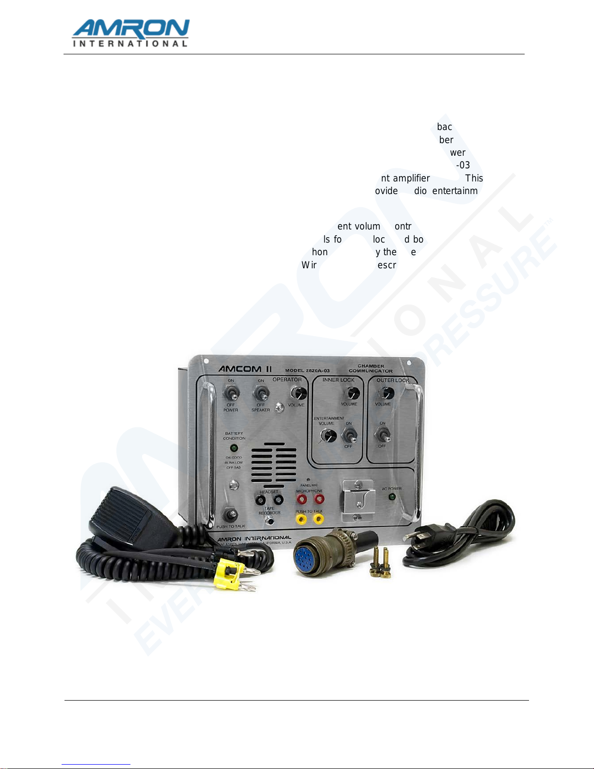
2820A-02 & 2820A-03 CHAMBER COMMUNICATOR USER MANUAL
i
TABLE OF CONTENTS
1INTRODUCTION...................................................................................................................................1
2SPECIFICATIONS................................................................................................................................2
2.1 ELECTRICAL................................................................................................................................2
2.2 MECHANICAL...............................................................................................................................2
3ACCESSORIES....................................................................................................................................3
3.1 AMRON HEAVY-DUTY HEADSET - MODEL 2401-28................................................................3
3.2 AMRON STANDARD HEADSET - MODEL 2460-28....................................................................3
3.3 AMRON SINGLE EARPIECE HEADSET – MODEL 2460SM-28.................................................3
3.4 AMRON CHAMBER HEADSET - MODEL 2460-31R...................................................................3
3.5 AMRON CHAMBER EXTENSION CABLE – MODEL 2460-31R-25............................................3
3.6 AMRON REMOTE WALK-AND-TALK MODULE - MODEL 2822-28...........................................3
3.7 AMRON REMOTE PUSH-TO-TALK MODULE - MODEL 2821-28..............................................3
3.8 AUDIO ADAPTOR CABLE - AMRON PART NUMBER 180-1000-00..........................................4
3.9 AMRON CHAMBER COMMUNICATION BOX – MODEL 3113...................................................4
3.10 AMRON CHAMBER COMMUNICATION BOX – MODEL 3113...................................................4
3.11 AMRON CHAMBER COMMUNICATION BOX – MODEL 3115...................................................4
3.12 AMRON CHAMBER COMBO BOX – MODEL 3125.....................................................................4
3.13 AMRON CHAMBER COMBO BOX – MODEL 3126.....................................................................4
3.14 AMRON CHAMBER JUNCTION BOX – MODEL 3127................................................................4
3.15 AMRON CHAMBER WIRING HARNESS – MODEL 3128...........................................................5
3.16 AMRON CHAMBER ENTERTAINMENT SPEAKER – MODEL 3130..........................................5
4CONTROLS AND CONNECTIONS......................................................................................................6
4.1 OPERATOR AND LOCK CONTROLS .........................................................................................6
4.2 OPERATOR CONNECTIONS ......................................................................................................8
4.3 BACK PANEL CONNECTIONS....................................................................................................9
4.4 DRAWING, OPERATOR HEADSET CONNECTIONS...............................................................11
4.5 DRAWING, PUSH-TO-TALK CONNECTIONS...........................................................................12
4.6 DRAWING, 2820A-02 & 2820A-03 TO CHAMBER WIRING DIAGRAM....................................13
5OPERATION.......................................................................................................................................14
5.1 CHARGING THE BATTERY.......................................................................................................14
5.2 INITIAL POWER ON - BATTERY CONDITION CHECK............................................................14
5.3 OPERATING ON AC POWER....................................................................................................15
5.4 MODES OF OPERATION...........................................................................................................15
5.5 SETTING THE VOLUME CONTROLS.......................................................................................15
6MAINTENANCE..................................................................................................................................17
6.1 CHAMBER COMMUNICATOR CHECK PROCEDURES...........................................................17
6.2 GENERAL MAINTENANCE........................................................................................................18
6.3 RECOMMENDED MAINTENANCE SCHEDULE.......................................................................18