manuals.online logo
Brands
  1. Home
  2. •
  3. Brands
  4. •
  5. AMSEC
  6. •
  7. Lock
  8. •
  9. AMSEC 5BE User manual

AMSEC 5BE User manual

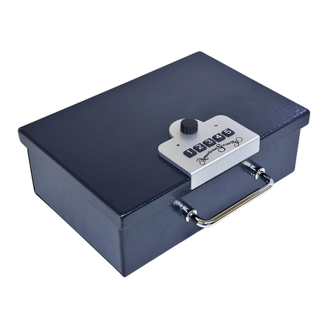
5-Button Electronic Lock
Model 5BE
Operating Instructions
Revised February, 2005
American Security Products Co.
11925 Pacific Avenue
Fontana, CA 92337
800-421-6142
http://www.amsecusa.com
Not responsible for typographical errors.
Manufacturer reserves the right to make changes as necessary.
Quick Reference
To Open the Lock on the factory code:
Press 1-2-3-4-5 and then turn knob clockwise about 90 degrees.
To Set the Primary Code:
Lock the safe OPEN. Press the change button once; then enter
5 keystrokes for the new primary code. Test the new code.
To Set the Backup Code:
Lock the safe OPEN. Press the change button twice; then enter
8 keystrokes for the new backup code. Test the new code.
To Set the Features:
Press the change button three times.
One Beep = On, Two Beeps = Off
Button 1 = LED Lamp.
Button 2 = Beeper.
Button 3 = Duress Signal.
Wait until the red LED shuts off.
To Send a Duress (Silent) Signal:
Enter your code (primary or backup), then press keys 1 and 5
simultaneously within three (3) seconds of your final key-
stroke, then turn the knob to open.
2 7
AMSEC 5-Button Electronic Lock Model 5BE Operating Instructions Revised February, 2005
Programming
The 5BE lock is programmable, so the user can change codes and con-
trol features.
To Set the Primary Code:
1. Lock the safe OPEN.
2. Press the change button once.
3. Enter five (5) keystrokes for the new primary code.
4. Test the new code.
To Set the Backup Code:
Lock the safe OPEN.
Press the change button twice.
Enter eight (8) keystrokes for the new backup code.
Test the new code.
To Set the Features:
¾Press the change button three times to activate the feature
programming mode.
¾The features are “assigned” to individual buttons on the key-
pad when you are in the feature programming mode.
¾A feature is turned ON by pressing the button for that fea-
ture and the unit sounds one (1) beep.
¾A feature is turned OFF by pressing the button for that fea-
ture and the unit sounds two (2) beeps.
¾Repeated pressing of a feature button will toggle the feature
ON/OFF
¾Button Assignments are:
1. Button 1 = LED Lamp.
2. Button 2 = Beeper.
3. Button 3 = Duress Signal.
When finished with programming, stop pressing buttons and wait
10 seconds for the red LED lamp on the keypad to shut off.
Duress Alarm (a.k.a. Silent Signal Alarm) is a feature that allows the
user to signal secretly they are in a troubled condition, such as a rob-
bery or an intruder in the home.
¾Provides a silent and safe means to summon help in an emer-
gency.
¾The Duress Alarm feature must be turned ON to provide signal-
ing. See Programming section for details.
¾The Duress Signal can be sent without an observer realizing a
signal has been activated.
¾The Duress Signal is activated by pressing 1 and 5 keys simul-
taneously after the final Keystroke of a valid code.
¾The lock will respond and open normally when the Duress
Signal has been activated.
¾Requires hard-wiring to an alarm system that has appropriate
capabilities and is monitored for emergency response.
¾The Duress Signal output makes a connection for three (3) sec-
onds when activated.
Open Door Signaling is a feature that provides an output signal when-
ever the lock is in an open condition, so that an Alarm System can notify
the user or a monitoring service that the safe is unlocked.
¾A microswitch inside the lock detects the position of the locking
pin, and this position sensing is provided as an output signal in
the output port.
¾The output is turned ON when the lock is unlocked, and holds
for 30 seconds until the lock goes to sleep.
¾If the lock goes to sleep (over 30 seconds in an open condition),
the output sends a two (2) second signal when the lock is
locked.
¾Requires hard-wiring to an alarm system that has appropriate
capabilities.
Detailed Instructions
The AMSEC 5BE lock is an electronic light-duty safe lock. This lock pro-
vides for quick access to a security container with high reliability and lit-
tle effort. Specifications and operation subject to change.
Operating Information
¾There are two programmable “codes” in the lock; a “Primary”
code that requires five (5) keystrokes, and a “Backup” code that
requires eight (8) keystrokes.
¾A “Keystroke” can be one button, or two buttons pushed simulta-
neously.
¾For instructional purposes, the Buttons are numbered 1 thru 5
starting at the button furthest from the knob.
¾The “Primary” code is for everyday use. The “Backup” code is
provided so the user can have a means to access the safe in
the event they forget their Primary Code. The Backup Code
should be set to some unique combination, and kept in a secure
location (not inside the safe).
¾The “Factory” Primary code is 1 – 2 – 3 – 4 – 5.
¾The Backup Code is not kept at the factory. Every 5BE lock
comes with the same Backup Code.
¾The Factory Backup Code is 1 – 5 – 2 – 4 – 3 – 1/5 – 2/4 – 3,
where the X/X numbers are Keystrokes that are pressed simul-
taneously. The consumer should change this code to provide
optimum security.
¾The 5BE lock can be programmed (see Programming section).
•The lock can be programmed for Silent Mode, where the
beeper will not sound during normal operation.
•The optional LED Lighting Lamps can be turned on or off.
•The optional Duress Alarm feature can be turned on or off.
6 3
AMSEC 5-Button Electronic Lock Model 5BE Operating Instructions Revised February, 2005
¾The 5BE lock has a Penalty Lockout feature to prevent tamper-
ing (code testing).
•This feature will cause the lock to stop accepting input for
five (5) minutes after four (4) incorrect opening attempts.
•While in Penalty Lockout, the lock will respond to any key-
stroke with eight (8) rapid flashes of the red LED lamp,
along with beeps (if the beeper is turned on).
•While in Penalty Lockout, the LED lamp will flash once
every five (5) seconds and beep (if the beeper is turned on).
¾When a correct code has been entered, Primary or Backup, the
Red LED Lamp will light for three (3) seconds, indicating the
lock can be opened.
•To open the lock, turn the knob Clockwise 90 degrees.
¾The 5BE lock uses a standard 9VDC Alkaline Battery.
•We recommend Duracell® or Eveready Energizer® batteries
for best performance.
•The battery is located inside the internal lock body, at one
end, under a hatch.
•To replace the battery, pull the hatch open and remove the
battery from the cavity. Unclip it form the terminals, and clip
on a new battery, tuck the wires in neatly and press firmly to
close the hatch.
•The 5BE lock should open approximately 5000 times with
fresh, good quality batteries, depending on installed options
and user habits.
¾The 5BE lock provides a backup power port to prevent lockout if
the primary battery is allowed to go dead.
•Under a door next to the knob on the keypad, you will find
terminals to allow connection of a fresh secondary 9VDC
battery.
¾Loss of power will not erase codes. The 5BE lock uses “non-
volatile” memory.
¾On the side of the lock body, you will find a small black button
used to program codes and features.
¾The 5BE lock provides two auxiliary outputs for connection to
alarm or monitoring services.
•There is a four (4) position socket in the side of the lock
body to provide connections. An optional cable is available
to plug into this port for installation connection.
•Two outputs are provided; one for “Duress” signaling and
the other for “Open Door” signaling.
•The outputs are solid state switches, and therefore are
polarity sensitive and can only be used to switch DC sig-
nals. Do not connect any AC power source to these ports.
•The output ports are rated for 12 VDC, 500 mA maximum.
¾This lock is not waterproof, and is not intended for outdoor use.
Exposure to extreme conditions or excess moisture may cause
a malfunction, and will void the Manufacturers Warranty.
Optional Features and Operation
The 5BE lock provides two advanced signaling features, LED Lighting,
Duress Alarm and Open Door Signaling.
LED Lighting is an optional piece of equipment (sold separately) that
provides a light source when the safe is open.
¾The LED Lamp Option plugs into a two (2) pin port on the side
of the lock.
¾The LED Lamp Option consists of a pair of high intensity white
LED Lamps in a wired housing that can be attached to the safe
in an appropriate position to provide light inside the safe when it
is open.
¾The LED Lamp Option must be turned ON to operate. See
Programming.
¾The LED Lamp will turn on when the lock is opened, and remain
on for 30 seconds (until the lock goes to sleep). If you press any
keypad buttons, the light will turn on again for another 30 sec-
onds. A key-press while the lights are on will restart the 30 sec-
ond shut-off timer.
¾Use of the LED Lamp Option will diminish the cycle life of the bat-
teries by some factor, depending on use frequency and duration.
4 5
AMSEC 5-Button Electronic Lock Model 5BE Operating Instructions Revised February, 2005

Other AMSEC Lock manuals

AMSEC ESL15 User manual

AMSEC

AMSEC ESL15 User manual

AMSEC ESL20XL User manual

AMSEC

AMSEC ESL20XL User manual

AMSEC Simplex User manual

AMSEC

AMSEC Simplex User manual

AMSEC ESL10 User manual

AMSEC

AMSEC ESL10 User manual

AMSEC ESL20 User manual

AMSEC

AMSEC ESL20 User manual

AMSEC ESL10XL User manual

AMSEC

AMSEC ESL10XL User manual

AMSEC SafeWizard II User manual

AMSEC

AMSEC SafeWizard II User manual

AMSEC BSL-0601A-W User manual

AMSEC

AMSEC BSL-0601A-W User manual

AMSEC PB3 User manual

AMSEC

AMSEC PB3 User manual

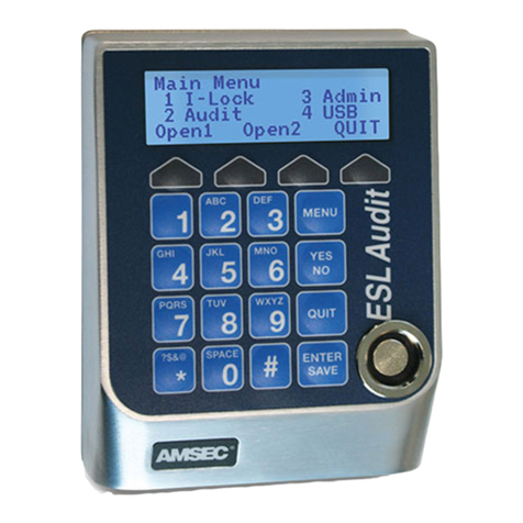
AMSEC ESLAudit User manual

AMSEC

AMSEC ESLAudit User manual

AMSEC ESL15 User manual

AMSEC

AMSEC ESL15 User manual

Popular Lock manuals by other brands

DatoHome L-B400 manual

DatoHome

DatoHome L-B400 manual

Lockly Vision PGD798SN user manual

Lockly

Lockly Vision PGD798SN user manual

Alarm Lock Wireless Networx PDLN4100 Programming instructions

Alarm Lock

Alarm Lock Wireless Networx PDLN4100 Programming instructions

Borglocks BL2605MG Installation Guide, Parts List & Maintenance Instructions

Borglocks

Borglocks BL2605MG Installation Guide, Parts List & Maintenance Instructions

Sealey FPS7 instructions

Sealey

Sealey FPS7 instructions

Dormakaba STV 2 Series Mounting instructions

Dormakaba

Dormakaba STV 2 Series Mounting instructions

SITEMA KRGP Series operating manual

SITEMA

SITEMA KRGP Series operating manual

UCS BRAVO user manual

UCS

UCS BRAVO user manual

National Cabinet Lock C8111 Dimensional drawing

National Cabinet Lock

National Cabinet Lock C8111 Dimensional drawing

ENFORCER SD-72081-6MQ manual

ENFORCER

ENFORCER SD-72081-6MQ manual

Esco systeQ-M-B2H-ESC Installation, operation and maintenance instructions

Esco

Esco systeQ-M-B2H-ESC Installation, operation and maintenance instructions

Salto Clay IQ Installation

Salto

Salto Clay IQ Installation

DITEC DAS802LOKA installation manual

DITEC

DITEC DAS802LOKA installation manual

Amazon B07T5MMHXS quick start guide

Amazon

Amazon B07T5MMHXS quick start guide

Lockwood 3578 Series Mounting instructions

Lockwood

Lockwood 3578 Series Mounting instructions

Assa Abloy 836S Fitting instructions

Assa Abloy

Assa Abloy 836S Fitting instructions

National Cabinet Lock C8704 Dimensional drawing

National Cabinet Lock

National Cabinet Lock C8704 Dimensional drawing

DOM RONIS CoverK Assembly

DOM

DOM RONIS CoverK Assembly

manuals.online logo
manuals.online logoBrands
  • About & Mission
  • Contact us
  • Privacy Policy
  • Terms and Conditions

Copyright 2025 Manuals.Online. All Rights Reserved.