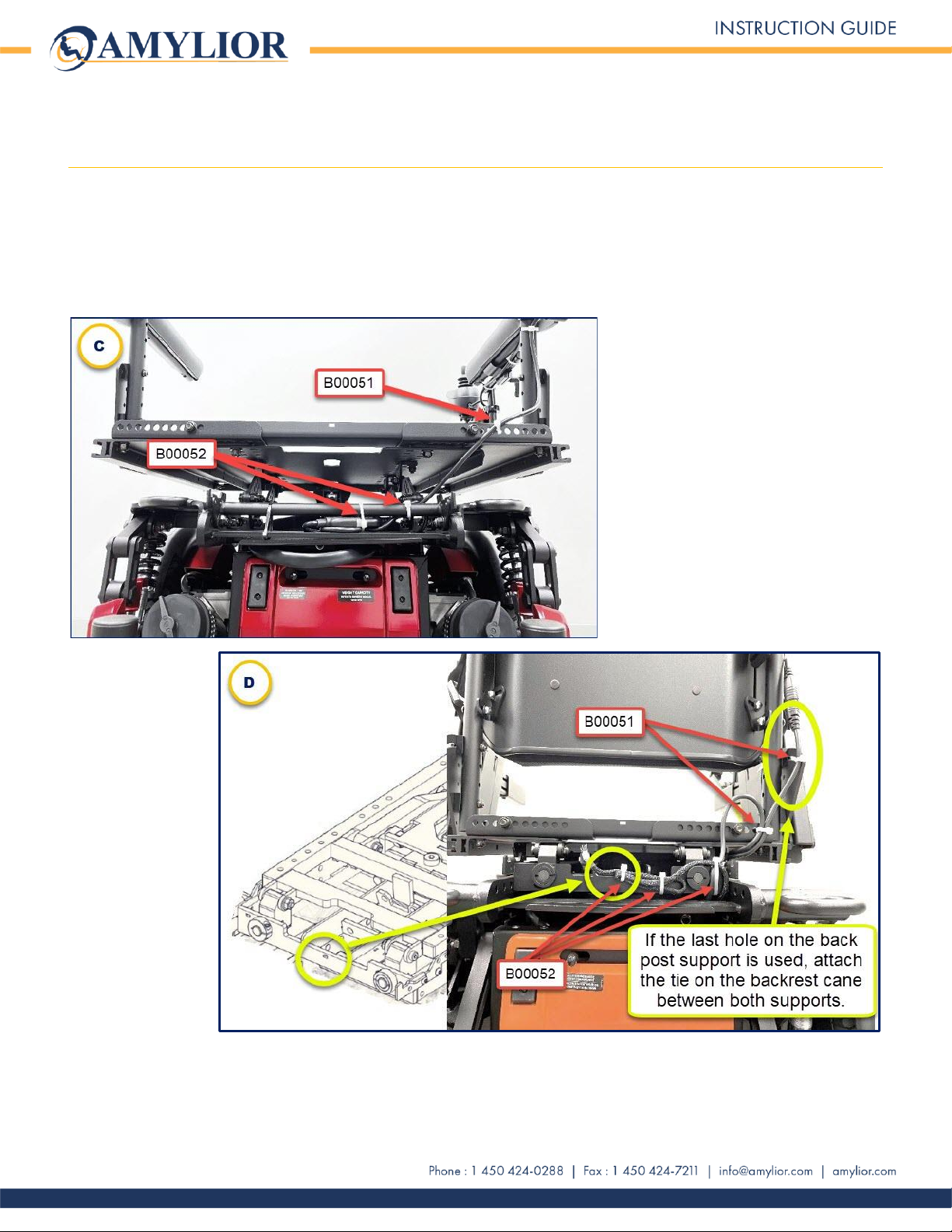
Joystick Cable Wiring (cont’d)
6
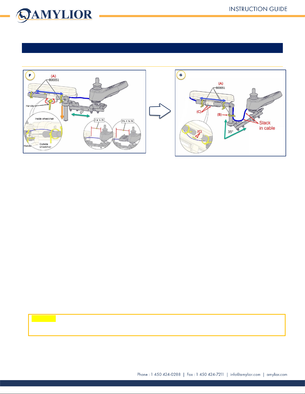
3. Adjusting a fixed or swing away joystick
Changing the angle of a joystick mount from the factory-standard of 0° to 35°
a) Using cutters, cut and remove B00051 ties (A) as shown in image F.
b) To change the angle from 0° to 35°, (Orange arrow, image F) slide arm all the way down the vertical rod as
shown in image G. Refer to the “Joystick Adjustment”section of the Owner’s Manual for more details on angle
adjustment.
c) If more cable is needed, refer to previous sections 1 and 2 to retrieve more cable as required and re-attach
afterwards. Leave a slack in the angle of the cable as shown in image G. Add an extra 1 inch of cable to allow
the joystick to swing away freely.
d) As shown in image G, as well as attaching the cable with two B00051 ties (A) on the horizontal rod (Depth
adjustment), an additional B00051 tie (B) must be attached to the vertical rod (Height adjustment).
e) Adjusting the DEPTH of a swing away joystick:
For a dual post armrest (Image G)
•Using a 4 mm Allen key, loosen both screws underneath the armrest (C) to release the horizontal rod
allowing it to move left to right/right to left (blue arrow in image G).
•Route the cable along the rod as shown in the circle of image G. Once desired depth is reached, tighten
screws.
For a cantilever or reclining armrest (Image F)
•Loosen the handle (Red arrows in image F) to release the horizontal rod allowing it to move left to
right/right to left (blue arrow).
•Route the cable along the horizontal rod as shown in the circle on the left side of image F. Once desired
depth is reached, tighten handle.
WARNING: The slack in the cable to allow the joystick to swing away freely, should not exceed 1 inch. Do not
let any cable stick out from the wheelchair or form a loop that could catch on external objects when moving
around in the chair. This could cause severe damage in the wheelchair’s components or power supply.