Amylior EOLP2-RNET-T Manual

1 IG ︱P22030︱R01︱2023-01
INSTALLATION OF LED LIGHTING PACKAGE
WITH TURN SIGNALS

2 IG ︱P22030︱R01︱2023-01
TABLE OF CONTENTS
INTRODUCTION ........................................................................................................................................... 3
1. Replacement parts packages............................................................................................................3
2. List of tools required.........................................................................................................................3
ASSEMBLY & INSTALLATION....................................................................................................................... 4
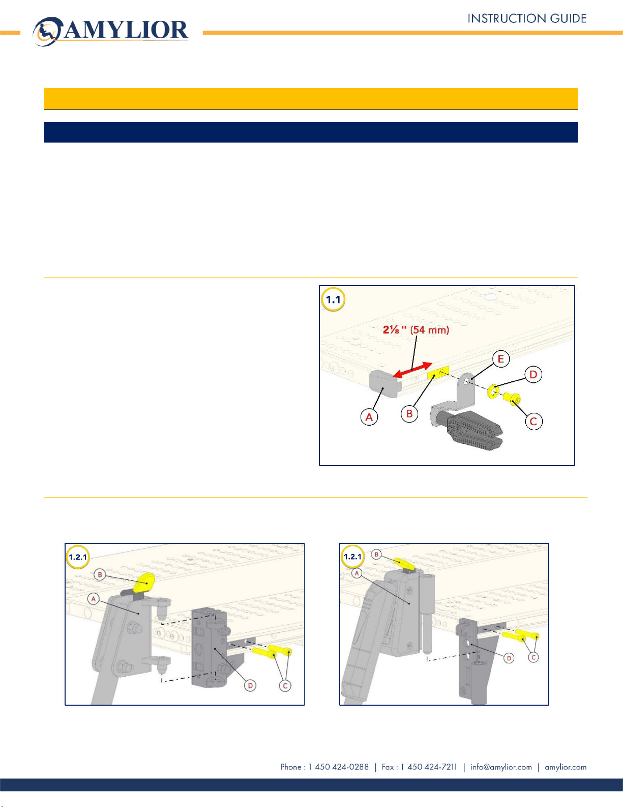
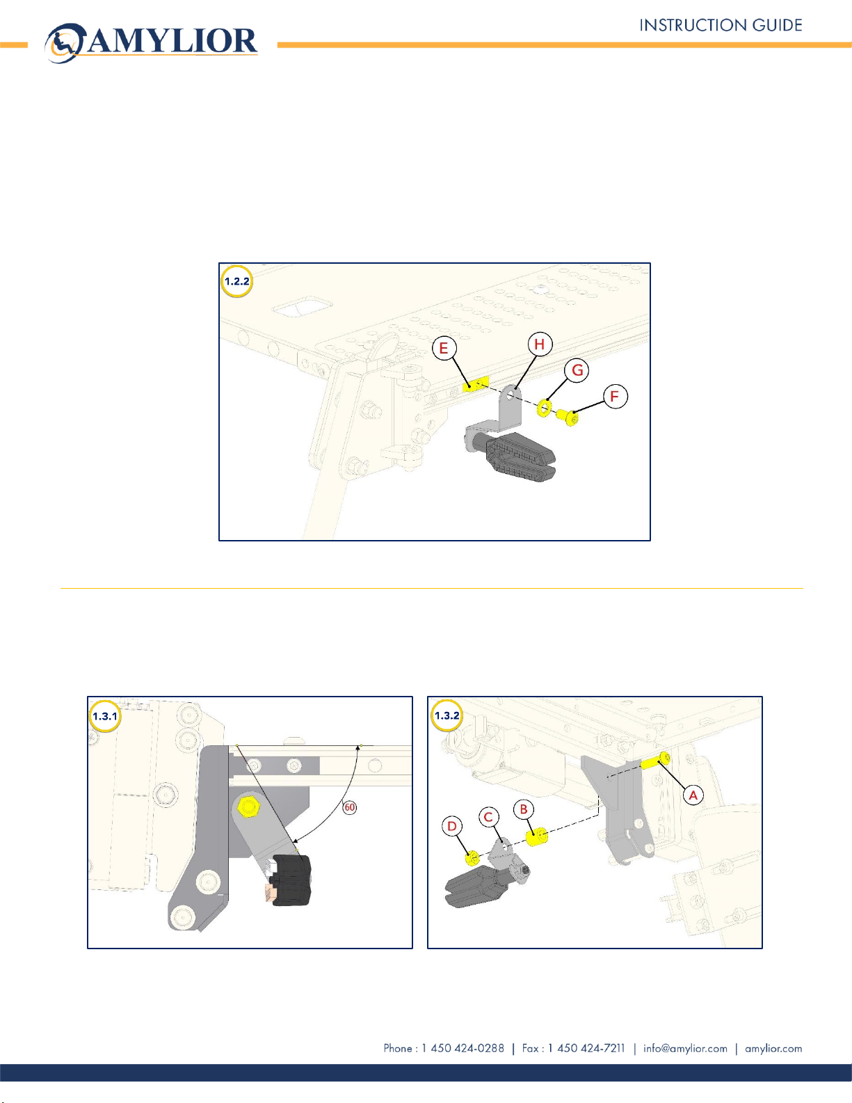
1. Installing FRONT safety lights with turn signals ................................................................................4
1.1. Installing lights on chairs with a Center Mount Legrest..........................................................4
1.2. Installing lights on chairs with separate legrests for adult, pediatric and HD models ............4
1.3. Installing lights on chairs with power legrests. .......................................................................5
1.4. Installing lights on chairs with knee blocks (Stander) .............................................................6
2. Installing REAR safety lights with turn signals ...................................................................................6
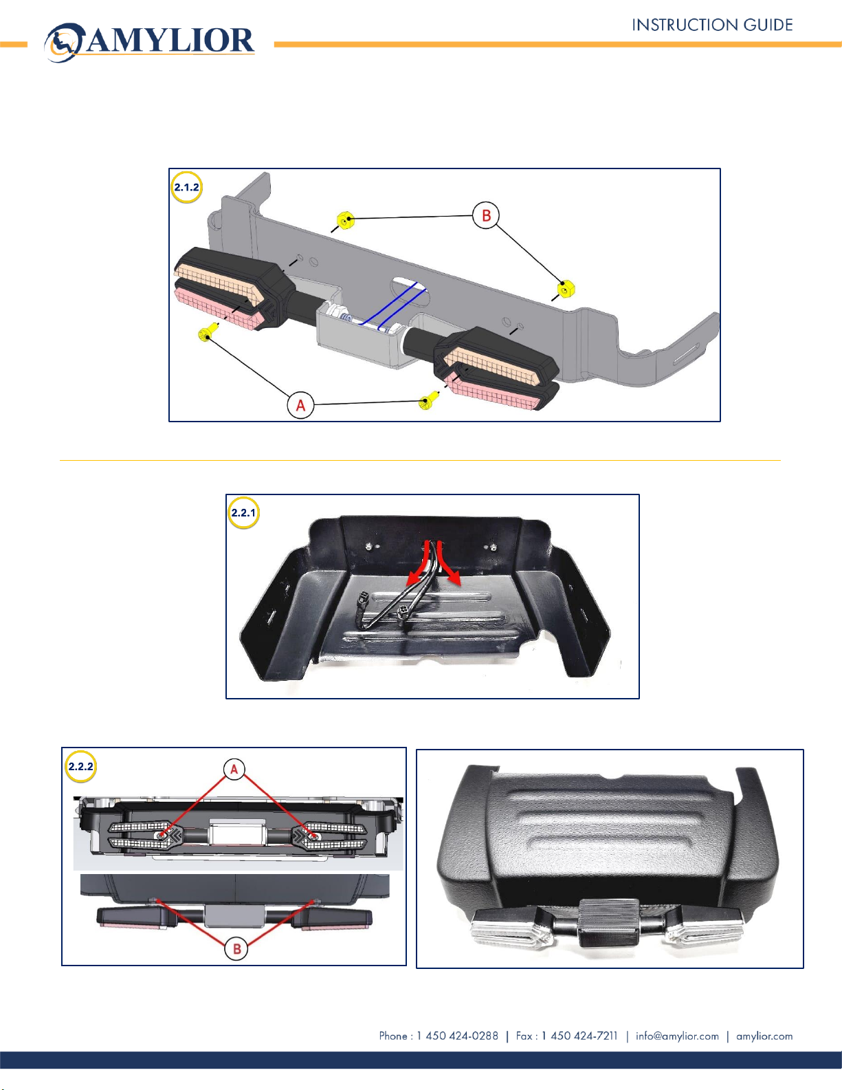
2.1. Installation onto the power module shroud of chair with tilt..................................................6
3.1. Installation onto the power module shroud with combo (tilt and elevate) .............................7
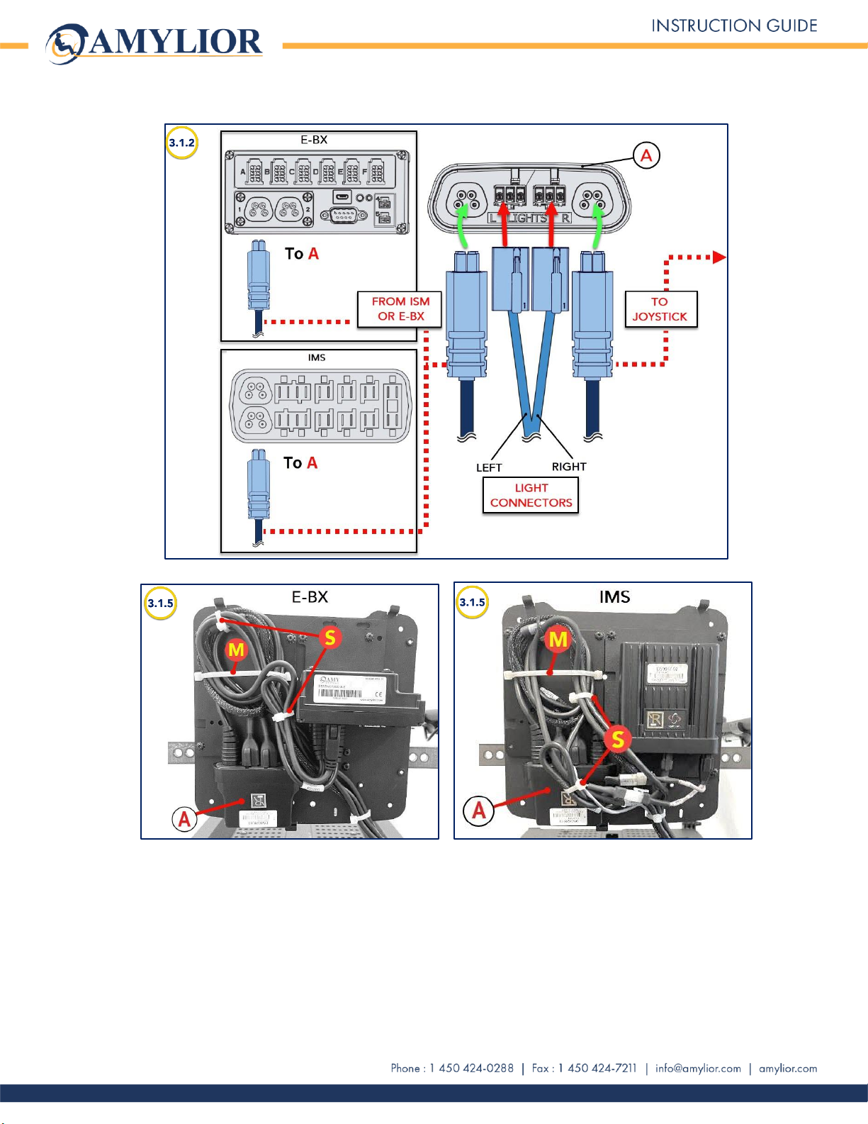
CONNECTING AND WIRING CABLES ......................................................................................................... 8
3. Installing R-net cable onto the backrest ...........................................................................................9
3.1. On a fixed backrest ................................................................................................................9
3.2. On a power recline backrest ................................................................................................11
4. Installing REAR safety lights with an R-NET cable ..........................................................................12
4.1. For a power tilt.....................................................................................................................12
4.2. For a power combo (tilt/elevate)..........................................................................................13
5. Installing REAR safety lights with a VR2 controller..........................................................................14
5.1. Without tilt ...........................................................................................................................14
5.2. With tilt ................................................................................................................................15
6. Installing cable underneath the seat pan (except for the Stander) .................................................16
7. Installing safety light cables for a STANDER................................................................................... 17
7.1. From the backrest ................................................................................................................17

LED Safety Light Package Installation (cont’d)
3 IG ︱P22030︱R01︱2023-01
INTRODUCTION
The intention of this guide is to provide technicians step by step instructions for installing the Amylior
lighting system onto all Alltrack power wheelchairs. This includes front and rear safety lights, the light
module, connections, and proper wiring and securing cables.
1. Replacement parts packages
Order Form
reference
number
EOLP2-RNET-T, EOLP2-RNET-TR, EOLP2-RNET-TR-DUAL, EOLP2-VR2
Part Number
Description
1004183
LEFT FRONT Safety Light Package including hardware.
1004184
RIGHT FRONT Safety Light Package including hardware.
1004185
REAR (LEFT 1004045, RIGHT 1004046) Safety Light Package
including hardware
1004186
R-NET Safety Light Package including module, hardware, and harness
1004187
VR2 Safety Light Package including module, hardware, and harness
1004188
R-net STANDER Safety Light Package including module, hardware, and
harness
2. List of tools required
Allen keys: 3⁄16" or 5 mm and
5⁄16" / 8 mm
Wrenches: 5⁄16" / 8 mm and
7⁄16" / 11 mm
Cutter pliers
Phillips Screwdriver

LED Safety Light Package Installation (cont’d)
4 IG ︱P22030︱R01︱2023-01
ASSEMBLY & INSTALLATION
1. Installing FRONT safety lights with turn signals
IMPORTANT:
Installation of front safety lights are done according to the power wheelchair’s CONFIGUTATION.
NOTE - For simplicity, this guide focuses on the installation of the lights on the left side of the chair, as
viewed from the seated position. The terms “safety lights” and “lights” will be used
interchangeably.
1.1. Installing lights on chairs with a Center Mount Legrest.
1.2.1. Remove the seat pan endcap A. Slide
part B along the track and place it at 2⅛"
from the front of the seat pan.
1.2.2. Using a 3⁄16" Allen key, firmly tighten
screw C to part Bpassing through
washer Dand bracket E.
1.2.3. Reinstall endcap A.
1.2. Installing lights on chairs with
separate legrests for adult,
pediatric and HD models
1.2.1. Remove legrest A by pressing quick-release lever Bas shown in images 1.2.1 below. Using
a 3⁄16" Allen key and a 7⁄16" wrench, unscrew both Cscrews to remove legrest support D.
Adult and pediatric models HD model

LED Safety Light Package Installation (cont’d)
5 IG ︱P22030︱R01︱2023-01
1.2.2. Slide part E along the track and place it at 2⅛" from the front of the seat pan as shown in
image 1.2.2 below.
1.2.3. Using a 3⁄16" Allen key, firmly tighten screw F to part Epassing through washer Gand
bracket H.
1.2.4. Reinstall legrest support D and insert legrest A into support hole(s). Refer to previous images
1.2.1.
1.3. Installing lights on chairs with power legrests.
1.3.1 Install light bracket on the inner section of the legrest support as shown in image 1.3.1 below,
keeping a 60° angle from top of seat pan.
1.3.1 As shown in image 1.3.2, insert screw Ainto the hole of the inner section and join spacer B,
bracket C, and nut Dusing a 3⁄16" Allen key and a 7⁄16" wrench. Tighten firmly.

LED Safety Light Package Installation (cont’d)
6 IG ︱P22030︱R01︱2023-01
1.4. Installing lights on chairs with knee blocks (Stander)
1.4.1. Install light bracket on the inner section of the legrest support as shown in image 1.4.1 below,
keeping an 85° angle from top of seat pan.
1.4.2. As shown in image 1.4.2, insert screw Ainto the hole of the inner section and join spacer B,
bracket C, and nut Dusing a 3⁄16" Allen key and a 7⁄16" wrench. Tighten firmly.
2. Installing REAR safety lights with turn signals
2.1. Installation onto the power module shroud of chair with tilt
2.1.1. Insert light cables into shroud’s center opening.

LED Safety Light Package Installation (cont’d)
7 IG ︱P22030︱R01︱2023-01
2.1.2. Using a Phillips screwdriver and a 5⁄16" wrench, attach light support onto shroud with screws A
and nuts B.
2.2. Installation onto the power module shroud with combo (tilt and elevate)
2.2.1. Insert light cables into the shroud’s center opening.
2.2.2. Using a Phillips screwdriver and a 5⁄16" wrench, attach light support onto shroud with screws A
and nuts B.

LED Safety Light Package Installation (cont’d)
8 IG ︱P22030︱R01︱2023-01
CONNECTING AND WIRING CABLES
WARNING: Regardless of where a cable is attached, it is very important not to let any cable stick out
from the wheelchair or form a loop that could catch on an external object when moving around with the
chair. This could cause severe damage to the wheelchair’s components or power supply.
NOTE: The yellow or white tie wraps shown in the images in the following pages are for illustrative
purposes only, as these ties are normally black.
Before making any adjustments, it is important to take photos or to note where and how the cables are
attached, so that they are placed in the same location and attached in the same way.
From this page on, pictures are for demonstration purposes only. They have been taken to help
illustrate instructions on connecting and wiring cables.
Tie Wrap legend:
•Small tie wrap (S) = 5½"/140 mm
•Medium tie wrap (M) = 7½"/190 mm
RECOMMANDATION - When attaching tie wraps, it is recommended that they not be fully tightened to
allow adjustments throughout the wiring.

LED Safety Light Package Installation (cont’d)
9 IG ︱P22030︱R01︱2023-01
3. Installing R-net cable onto the backrest
IMPORTANT: All cables must be secured, no exception.
3.1. On a fixed backrest
NOTE: The following instructions apply to both ISM and e-bx controllers.
3.1.1. Install light module Aon the backrest as shown in image 3.1.1 below. Hardware is included in
the Light Package.
3.1.2. Plug both connectors in module A (Left to L and Right to R) as shown on diagrams in
image 3.1.2.
3.1.3. Unplug the joystick cable from the controller (ISM or e-bx) and plug it into module A.
3.1.4. Connect module Ato controller (ISM or e-bx) with the R-net cable (included in Light Package).
3.1.5. Coil excess cables together without making loops that are too tight. Using S or M tie-wraps,
secure all cables onto the backrest as shown in images 3.1.5 below. Do not tighten completely
until all cables have been connected properly.
3.1.6. Please go to Section 7 Installing cable underneath the seat pan for proper wiring to the front
lights.

LED Safety Light Package Installation (cont’d)
10 IG ︱P22030︱R01︱2023-01

LED Safety Light Package Installation (cont’d)
11 IG ︱P22030︱R01︱2023-01
3.2. On a power recline backrest
3.2.1. Install light module Aon the backrest as shown in image 3.2.1 below. Hardware is included in
the Light Package.
3.2.2. Plug both connectors in module A (Left to L and Right to R) as shown in diagrams in image
3.1.2 (on the previous page).
3.2.3. Unplug the joystick cable from the controller (ISM or e-bx) and plug it into module A.
3.2.4. Connect module Ato controller (ISM or e-bx) with the R-net cable (included in Light Package.)
3.2.5. Coil excess cables together without making loops that are too tight. Using S or M tie-wraps,
secure all cables onto the backrest as shown in image 3.2.5 below. Do not tighten completely
until all cables have been connected properly.
3.2.6. Please go to Section 7 Installing cable underneath the seat pan for proper wiring to the front
lights.

LED Safety Light Package Installation (cont’d)
12 IG ︱P22030︱R01︱2023-01
4. Installing REAR safety lights with an R-NET cable
4.1. For a power tilt
4.1.1. Fit a sheath over cables coming from the backrest as shown in image 4.1.1 below.
4.1.2. Attach this sheath to the seat pan using an M tie wrap. Make sure that there is a loop large
enough (A) to allow the tilt movement.
4.1.3. Using S tie wraps, attach cables (from sheath) on the tilt module leaving enough play in the
cables to perform the following connections:
4.1.4. Plug both light connectors. The "REAR RIGHT" connector to the light cable labeled 1004046
and the "REAR LEFT" connector to the light cable labeled 1004045.
4.1.5. Install power module shroud.

LED Safety Light Package Installation (cont’d)
13 IG ︱P22030︱R01︱2023-01
4.2. For a power combo (tilt/elevate)
4..2.1. Fit a sheath over cables coming from the backrest as shown in image 4.2.1 below.
4..2.2. Attach this sheath to the seat pan using an M tie wrap. Make sure that there is a loop large
enough (A) to allow the tilt movement.
4..2.3. Using S tie wraps, attach cables (from sheath) on the tilt module leaving enough play in the
cables to perform the following connections:
4..2.4. Plug both light connectors to their respective light cable. Refer to previous image 4.1.4 for
identification.
4..2.5. Install power module shroud.

LED Safety Light Package Installation (cont’d)
14 IG ︱P22030︱R01︱2023-01
5. Installing REAR safety lights with a VR2 controller
5.1. Without tilt
5.1.1. Install light module Aon the frame’s crossbar* B, using M tie wraps.
* Depending on the seat pan’s height, the light module can be installed on the CENTER
crossbar, or the OUTER (rear) crossbar as shown in images 5.1.1 below. If the seat pan is high
enough, it is better to attach module A on the frame’s center crossbar.
5.1.2. Plug both light connectors. The "REAR RIGHT" connector to the light cable labeled 1004046
and the "REAR LEFT" connector to the light cable labeled 1004045. This applies to both types
of installations.
5.1.3. Using S tie wraps, attach all cables surrounding connectors going toward light module A. In
image 5.1.1 on the right, the tilt module has been painted white to better identify it.
5.1.4. Install power module shroud.

LED Safety Light Package Installation (cont’d)
15 IG ︱P22030︱R01︱2023-01
5.2. With tilt
5.2.1. Install light module Aon the frame’s crossbar* B, using M tie wraps.
* Depending on the seat pan’s height, the light module can be installed on the CENTER
crossbar, or the OUTER (rear) crossbar as shown in images 6.1.1 below. If the seat pan is high
enough, it is better to attach module A on the frame’s center crossbar.
5.2.2. Plug both light connectors. The "REAR RIGHT" connector to the light cable labeled 1004046
and the "REAR LEFT" connector to the light cable labeled 1004045. This applies to both types
of installations.
5.2.3. Using M tie wraps, attach cables onto the back of the tilt module. In image 5.2.1, the tilt
module has been painted white to better identify it. The connectors cables can be secured
with S tie wraps.

LED Safety Light Package Installation (cont’d)
16 IG ︱P22030︱R01︱2023-01
6. Installing cable underneath the seat pan (except for the Stander)
NOTE - The cable running underneath seat pan is secured with S tie wraps as shown in image 6.1.1
below. Do not tighten tie wraps completely to allow some adjustment all along the wiring.
6.1.1. Start at the rear right of the seat pan, route cable along the rail and attach using tie wraps in
holes.
6.1.2. Plug FRONT RIGHT connector (1) to light cable labeled 1004048 and route toward the front of
the seat pan.
6.1.3. Route cable along the front of the seat pan and attach using mounting holes. Continue toward
light cable labeled 1004047 and plug FRONT LEFT connector (2).
6.1.4. Once wiring is completed, make loops with excess cable, and tighten tie wraps. Avoid making
the loops too tight.

LED Safety Light Package Installation (cont’d)
17 IG ︱P22030︱R01︱2023-01
7. Installing safety light cables for a STANDER
7.1. From the backrest
7.1.1. Route cables from the light module (backrest) under the seat pan. Cables are first plugged
into the FRONT light cables (1) underneath the seat pan (middle green rectangle in image)
and second plugged into the REAR light cables (2) onto the back of the tilt module (bottom
green rectangle in image).
7.1.2. Thread the series of cables through the wire guides A under the seat pan as shown in image
7.1.2 below.
7.1.3. It is important to place cables in order as follows:
Cable Order (from right to left):
1. Stander Right
2. Stander Left
3. Stander Right Extension Cable
4. Stander Left Extension Cable
5. Tilt
6. R-net cable
7. Elevate
8. Connector cables for light cables
9. Others

LED Safety Light Package Installation (cont’d)
18 IG ︱P22030︱R01︱2023-01
7.1.4. FRONT light connectors (1): Plug both light connectors. The "FRONT LEFT" connector to the
light cable labeled 1004045 and the "FRONT RIGHT" connector to the light cable labeled
1004046. Refer to image 7.1.4 below.
7.1.5. Attach FRONT LEFT light connector cable to the seat pan using S tie wraps as shown in image
7.1.5 below. Proceed the same way for the FRONT RIGHT light connector cable.
7.1.6. Secure all cables, in order, onto the cable bracket B, using an M tie wrap as shown in image
7.1.6 on the previous page. Attach an S tie wrap to prevent cables from separating and
getting mixed up when the Stander closes. Do not tighten S tie wrap just yet.

LED Safety Light Package Installation (cont’d)
19 IG ︱P22030︱R01︱2023-01
7.1.7. Before threading cables through the last 2 wire guides B, fit a sheath over all cables and route
toward the back of the tilt module as shown in image 7.1.7 below. Attach this sheath at the
back of the tilt module using M tie wraps. It is important to leave a loop in the sheath Ato
allow the cables to follow the movement of the tilt.
7.1.8. REAR light connectors (2): Plug both light connectors. The "REAR LEFT" connector to the light
cable labeled 1004045 and the "REAR RIGHT" connector to the light cable labeled 1004046.
Secure cables with S tie wraps. Refer to previous image 7.1.4 and image 7.1.7 below.
IMPORTANT - Once the wiring is complete, tie wraps that were not tightened, to allow adjustments
along the way, must be tightened at this point. Be careful! Avoid over-tightening as it
may damage cables or prevent movement in the mechanisms.
This completes the LED Light Package Instruction Guide. If further information is required, please contact
This manual suits for next models
9
Table of contents
Other Amylior Wheelchair manuals

Amylior
Amylior ALLTRACK M3 User manual

Amylior
Amylior LOGO SILVER OutoHAIR User manual

Amylior
Amylior LogoSilver IzyChair User manual

Amylior
Amylior ALLTRACK Series Manual

Amylior
Amylior E-BX Manual

Amylior
Amylior Gs 500 User manual

Amylior
Amylior LogoSilver Alltrack R FOOT User manual

Amylior
Amylior LOGOSILVER OUTCHAIR S User manual

Amylior
Amylior E2Swwhh Manual

Amylior
Amylior Gs 300 User manual