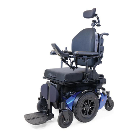
Amylior E-BX Manual

1
E-BX
IG-P17008-Instruction Guide E-BX R01

2
Table of contents
Table of contents......................................................................................................................................................2
1 Programming the wheelchair ...................................................................................................................................4
2 Adjusting R-Net settings ...........................................................................................................................................4
2.1 E-bx settings under the menu “Seating Amylior ISM”..................................................................................4
Actuator number and its functionality..........................................................................................................4
Settings under the “General” submenu........................................................................................................5
2.1.2.1 Settings under the “General” submenu ...............................................................................................5
Settings under the “Actuator Setup” submenu............................................................................................6
2.1.3.1 Settings under the “Actuator Setup” submenu....................................................................................7
Axis number allocation under the “Axis Setup” submenu............................................................................7
2.1.4.1 Table 1: Axis assignment of actuators for chairs without stander.......................................................8
2.1.4.2 Table 2: Axis assignment of actuators for chairs with stander ............................................................8
“Axis Setup” settings.....................................................................................................................................9
2.1.5.1 Settings under the “Axis Setup” submenu ...........................................................................................9
2.1.5.2 Approximate length of time for actuator deployment.......................................................................10
3 E-bx special boot-up modes and position reset. ....................................................................................................10
3.1 Overview of both special boot-up modes ......................................................................................................11
3.2 Activating special boot-up modes ..................................................................................................................11
3.3 First special boot-up mode.............................................................................................................................11
Table for the first special boot-up mode ....................................................................................................11
3.4 Second special boot-up mode ........................................................................................................................12
Table for the Second special boot-up mode...............................................................................................12
4 Troubleshooting guide............................................................................................................................................13
4.1 All about error codes......................................................................................................................................13
Error code reading on the joystick’s screen................................................................................................13
Error code reading by counting the number of times the indicator light underneath the e-bx flashes ....14
Error code reading using the program journal of the “R-Net Programmer” application...........................15
Error codes table.........................................................................................................................................18
Additional symptoms table.........................................................................................................................25
4.1.5.1 How to and additional information....................................................................................................28

3
4.1.5.1.1 Checking battery voltage..............................................................................................................28
4.1.5.1.2 Verifying power cables .................................................................................................................29
4.1.5.1.3 Verifying R-Net bus cables, actuator cables and intermittent problems.....................................33
5 Replacing pushbuttons in keypad (SWKEYPAD):....................................................................................................35
5.1 Pushbutton replacement................................................................................................................................35

4
1Programming the wheelchair
To ensure optimal programming on the Alltrack, use only Amylior’s instructions document, R-Net Programmer
software, and USB Dongle drivers from the website for the latest version.
Click Ctrl keytogether with this image
to access software downloads or use
QR code.
2Adjusting R-Net settings
2.1 E-bx settings under the menu “Seating Amylior ISM”
Actuator number and its functionality
To access all actuators controlled by e-bx, use the following path: “Seating Amylior ISM Actuator Setup”. In this
submenu, the legend for each actuator number is as follows:
1 = Seat tilt actuator
4 = Center mount legrest actuator
2 = Backrest recline actuator
5 = Left legrest actuator or left stander actuator
3 = Seat elevate actuator
6 = Right legrest actuator or right stander actuator
The functions assigned to actuators 5 and 6 depend on the chair’s power options. If the chair has the standing
option, actuators 5 and 6 will be assigned to the standing module. If the chair has the separate power legrests, then
the actuators 5 and 6 will be assigned to the left and right legrests.

5
Settings under the “General”submenu
The settings included the “General”submenu are all the adjustments available for setting minimum and maximum
limits on each actuator. The following table shows all the possible settings.
2.1.2.1 Settings under the “General” submenu
Settings
Applicable actuator
Description
Range
Defaut
settings
Min limit #1 (% or °)
Actuator #1 (Tilt)
Note 1
Minimum setting for tilt position (Angle between seat plate and chair
base). Note 2
0° to 46°
0
Max limit #1 (% or °)
Actuator #1 (Tilt)
Note 1
Maximum setting for tilt position (Full tilt) max angle between seat
plate and base.
0° to 46°
46
Min limit #2 (% or °)
Actuator #2 (Recline)
Minimum setting for backrest recline position (Angle between seat
plate and chair base).
91° to 160°
91
Max limit #2 (% or °)
Actuator #2 (Recline)
Maximum setting for backrest recline position (Fully reclined)
maximum angle between seat plate and base. Note 9
91° to 160°
160
Min limit #3 (% or °)
Actuator #3 (Elevate)
Note 4
Minimum setting for seat elevate position (Percentage of the range
of elevation). Note 2
0% to
100%
0
Max limit #3 (% or °)
Actuator #3 (Elevate)
Note 4
Maximum setting for seat elevate position (Fully elevated)
percentage of range. Note 3
0% to
100%
100
Min limit #4 (% or °)
Actuator #4 (Center
mount)
Minimum setting of center mount legrest position (Legrest fully
elevated) minimum angle between legrest and seat plate line. Note 5
92° to 5°
5
Max limit #4 (% or °)
Actuator #4 (Center
mount)
Maximum setting of center mount legrest position (Legrest fully
lowered).
92° to 5°
92
Min limit #5 (% or °)
Actuator #5 (Left
legrest)
Minimum setting of left legrest position (Legrest fully elevated)
minimum angle between legrest and seat plate line.
67° to 11°
11
Max limit #5 (% or °)
Actuator #5 (Left
legrest)
Maximum setting of left legrest position (Legrest fully lowered).
67° to 11°
67
Min limit #6 (% or °)
Actuator #6 (Right
legrest)
Minimum setting of right legrest position (Legrest fully elevated)
minimum angle between legrest and seat plate line.
67° to 11°
11
Max limit #6 (% or °)
Actuator #6 (Right
legrest)
Maximum setting of right legrest position (Legrest fully lowered).
67° to 11°
67
Min limit #5 (% or °)
Actuator #5 (Left
stander)
Minimum setting of left stander actuator (Standing module fully
deployed) minimum angle between the seat plate and the base
Notes 6 et 7
-70° to 0°
-68
Max limit #5 (% or °)
Actuator #5 (Left
stander)
Maximum setting of left stander actuator (Standing module
completely closed) Notes 6 et 7
-70° to 0°
0

6
Settings
Applicable actuator
Description
Range
Defaut
settings
Min limit #6 (% or °)
Actuator #6 (Right
stander)
Minimum setting of right stander actuator (Standing module fully
deployed) minimum angle between the seat plate and the base
Notes 6 et 7
-70° to 0°
-68
Max limit #6 (% or °)
Actuator #6 (Right
stander)
Maximum setting of right stander actuator (Standing module
completely closed) Notes 6 et 7
-70° to 0°
0
•Note 1 : Not applicable on actuators for very heavy-duty seat tilt (450 lb to 550 lb).
•Note 2 : If the chair has the power standing option, this setting should never be other than "0", otherwise
the standing function will not work.
•Note 3 : Setting the height limit can be determined with the following "rule of three": Height limit value
needed in % = (Height limit value in inches x 100)/11 inches (maximum height range).
E.g. Height limit value needed is 5.5 inches →(5.5 X100)/11 = 50%.
Therefore, the height limit value of Max limit #3 is 50%
•Note 4 : Not applicable on actuators for heavy-duty seat elevate (300 lb to 400 lb).
•Note 5 : If the chair has the power standing option, minimum setting of center mount legrest is 21°. It is
possible to change this value, but watch for leg hyperextention when in standing mode.
•Note 6 : Minimum and maximum limits for the left and right stander actuators must be set at the same
value.
•Note 7 : It is strongly recommended not to set this limit lower that -68° (example -70°) because the legrest
mechanism may collide with the base of the chair.
•Note 8 : This setting should never be other than "0" as this would prevent the seat tilt and seat elevate
from functionning.
•Note 9 : WARNING! If the chair has the power standing option, it is not recommended to change this
value because the backrest will not completely open to its vertical position which makes it dangerous for
the user who may risk being thrown forward.
Settings under the “Actuator Setup” submenu

7
“Actuator Setup” submenu displays all stander actuator settings for proper position angles to allow a
“comfortable” operation i.e. Soft start/stop. To adjust the stander actuator for a soft stop, use “Set point 1”. This
position is the first stop when the stander is deployed. This submenu also contains all the settings for actuator
movement speeds, acceleration/deceleration, starts and stops. The following table shows all the possible settings.
2.1.3.1 Settings under the “Actuator Setup” submenu
Settings
Applicable actuator:
Description
Range
Default setting
Set point 1
For stander actuators only:
Recline actuator (#2), center
mount actuator (#4) and
stander actuators (#5 & 6)
Soft stop angle adjustment in degrees
for recline, center mount and stander
actuators when standing function is
deployed.
Note 1 below
From minimum to
maximum values
under the “General”
submenu.
Recline: 155
Center mount legrest: 21
Stander: -60
Set point 11
Not used. Settings for future development.
Set point 12
Acceleration
For all actuators except the
stander actuator. The standing
module follows a specific
pattern when deployed and
do not consider these settings
Percentage value of speed acceleration
adjustment when actuator starts
moving. For a soft start, the value of this
setting is reduced.
1 % to 100 %
100
Deceleration
Percentage value of speed deceleration
adjustment when actuator stops
moving. For a soft stop, the value of this
setting is reduced
Up Speed
Percentage value of actuator speed
when deploying (opening).
25% to 100%
Down Speed
Percentage value of actuator speed
when retracting (closing).
•Note 1 : The angle for stander actuators 5 and 6 must be set at the same value.
Axis number allocation under the “Axis Setup”submenu.
Under this submenu, there are twelve axis numbers which correspond to a specific function. Each axis can control
between 0 to 6 actuators at the same time according to their predetermined functions. These axes can also
control operations such as standing, memory setting and actuator position recalling.

8
For chairs without the power standing option, the following table shows basic functions assigned to each axis.
2.1.4.1 Table 1: Axis assignment of actuators for chairs without stander
Axis number
Function/Actuator
1
Tilt
2
Recline
3
Seat elevate
4
Left legrest
5
Right legrest
6
Left & right legrests
7
Recline and Left & right legrests
8
Center mount legrest
9
Recline and Center mount legrest
10
Not used
11
Memory positions 1 & 2
12
Memory positions 3 & 4
For chairs with the power standing option, the following table shows basic functions assigned to each axis.
2.1.4.2 Table 2: Axis assignment of actuators for chairs with stander
Axis number
Function/Actuator
1
Tilt
2
Recline
3
Seat elevate
4
Not used
5
Not used
6
Not used
7
Not used
8
Center mount legrest
9
Recline and Center mount legrest
10
Stander
11
Memory positions 1 & 2
12
Memory positions 3 & 4

9
“Axis Setup” settings
These settings are for adjusting certain movements on the different power options.
The following table shows all the possible settings.
2.1.5.1 Settings under the “Axis Setup” submenu
Settings
Applicable actuator:
Description
Range
Default setting
Parameter E
Not used. Settings for future development.
Parameter F
Acceleration
Standing function only
Percentage value of speed acceleration
setting when actuators start moving for the
stander’s deployment. .
1% to 100%
Note 1
100
Deceleration
Standing function only
Percentage value of speed deceleration
setting when actuators stop moving after the
stander’s retraction. .
Up Speed
Standing function only
Percentage value of deployment speed of
actuators for the standing function.
25% to 100%
Note 1
Down Speed
Standing function only
Percentage value of retraction speed of
actuators for the standing function.
Control
All functions assigned
to an axis number
Performance setting for the joystick
controlling the axes. In non-proportional
mode, whether toggling lightly or with
intensity, forward or backward, actuators
assigned to an axis will move at the speed
setting found in the “Actuator Setup” or “Axis
Setup” submenus (for stander speed). In
proportional mode, the speed of actuators
assigned to an axis will vary according to the
joystick’s position forward or backward.
When toggled all the way, the speed of
actuators assigned to an axis with move at
the speed setting found in the “Actuator
Setup” or “Axis Setup” submenus (for stander
speed).
Non-proportional
or proportional
mode
All axes are
adjusted to
proportional
mode except for
Axis 10 of the
stander.
Note 2

10
Settings
Applicable actuator:
Description
Range
Default setting
Latched Actuators
All functions assigned
to an axis number
Enables or disables the latch option. The latch
option maintains movement of the actuators
assigned to an axis for a length of time. When
this option is enabled, any movement on an
axis will make all actuators for this axis move
and maintain motion for a certain length of
time. You can stop this movement, at any
time, by pressing any buttons on the keypad
(SWKEYPAD) or by toggling joystick forward or
backward. Note 3
No or Yes
No
Latched Timeout
All functions assigned
to an axis number
Setting the length of time that the actuators
for the axis are in motion. Note 4
0 to 250s
10s
Latched Timeout Beep
All functions assigned
to an axis number
Enables or disables the joystick’s audible
warning that can be heard at around 2
seconds before the latched mode movement
ends.
No or Yes
Yes
•Note 1 : Even though the standing function is adjustable, it is recommended not to change the value of
these two settings. This can affect the standing function’s performance and create errors while in motion.
Before modifying these settings, contact Amylior for approval.
•Note 2 : Even though the Control setting for the standing function’s axis is adjustable, it is recommended
not to change the setting to “proportional”. This can affect the standing function’s performance and
create errors while in motion. Before modifying this setting, contact Amylior for approval.
•Note 3 : For both axes reserved for memory positions (#11 & #12), Control must be set to non-
proportional for the Latched Actuators to work properly.
•Note 4 : The length of time from the minimum position to the maximum position (deployment) for each
actuator should be around the times shown in the following table.
2.1.5.2 Approximate length of time for actuator deployment
Recline: 26s
Seat elevaste: 23s
Right & Left legrests: 30s
Tilt: 22s
Center mount legrest: 25s
Stander (from the minimum position to the Soft Stop
“comfortable” position): 47s
Note that the default values were established for the chair’s optimal comfort and performance. It is
recommended to be very careful and vigilent before modifying any settings.
3E-bx special boot-up modes and position reset.
WARNING!
Never use special boot-up modes if the user is in the chair. This can cause serious injury to the user. When these
modes are in use, actuator movement limits are temporarily disabled and can create major mechanical conflicts.
These modes should only be used for troubleshooting different problems with the chair. Handle with care as there is
also a risk of damaging some of the chair’s mechanisms or components. Judgement and vigilance are key while using
these special boot-up modes. To exit the mode once it is no longer needed, turn the chair off and turn it back on.

11
3.1 Overview of both special boot-up modes
There are two special boot-up modes on the e-bx. These modes are very useful tools for technicians to determine
the cause or sources of power option failure; to boot-up actuators that may have lost their positioning; or to
replace a defective actuator related to the e-bx. Each mode has its own distinctive features.
3.2 Activating special boot-up modes
When the button underneath the e-bx is held during system start-up, the green LED flashes with a delay of two
seconds. The number of flashes corresponds to the mode required. Release the button when the number of
flashes equals the mode required. Therefore, if the first mode is required, release the button at the first green LED
flash and if the Second mode is required, release at the second flash.
Tables in this section provide a summary of features for each mode.
3.3 First special boot-up mode
This mode was designed to help determine if an actuator is defective or if it stopped moving because of a problem
with the controller. This mode can also be used for an actuator position reset. In this mode, all movement
limitations will be disabled except for minimum and maximum limits for each actuators under the "General"
submenu (section 2.1.2.1.)
Table for the first special boot-up mode
Number of green LED
flashes at start-up on
the e-bx
Mode 1 indications
What becomes
disabled
Applicable actuators
Features
1
•Red light left
of the
pushbuttons
(SWKEYPAD)
flashes
constantly.
•Power options
are displayed
in “seating” on
joystick screen
Actuator movement
limits are disabled. If
actuator positioning
system is defective,
movement will not be
possible.
•Tilt (1). See Note 1
•Recline (2). See Note 1
•Seat elevate (3).
See Note 1
•Center mount legrest
(4). See Note 2
•Left legrest (5).
See Note 1
•Right legrest (6).
See Note 1
•Left stander (5).
See Note 2
•Right stander (6).
See Note 2
•Allows a minimum and maximum
position reset of any actuator that
are not defective.
•Works with joystick and pushbutton
keypad (SWKEYPAD)
•Possible error warnings are not
disabled
•The stander operates normally and
will automatically soft stop at the
comfortable position.
•The chair is not restricted in its
driving by default except for normal
limit settings.

12
•Note 1: Resetting actuators using the first special boot-up mode
For custom limits: Note all settings beforehand. Replace them with values shown in the Default Settings
column of the General submenu table (Section 2.1.2.1) and then proceed to a position reset of actuator(s).
Restore the settings to their original values before returning the chair to the user.
•Note 2: Resetting stander actuators using the first special boot-up mode
For the standing function, the center mount legrest actuator minimum limit and that of the stander
actuators are not set to the minimum physical limit of these actuators. Since the value shown in the
Default Settings column of the General submenu table (Section 2.1.2.1) is not the minimum physical limit
of stander actuators, the values must be replaced as follows:
→
Once these values are set, procced with a position reset of the center mount legrest actuator or of the stander
actuators through the first special boot-up mode.
Important! Prior to modifying settings, take note of the original values. These values will be restored before
returning the chair to the user.
3.4 Second special boot-up mode
Once the Second special boot-up mode is accessed, a position reset of actuators can be done by moving the
targeted actuators from the minimum position to the maximum position using the keypad (SWKEYPAD). Retract all
actuators to neutral position before exiting this mode and return to normal mode by turning chair off and back on.
To execute a position reset, refer to the Features column in the table below.
Table for the Second special boot-up mode
Number of green LED
flashes at start-up on
the e-bx
Mode 2 indications
What becomes
disabled
Applicable
actuators
Features
2
•Red and green
LEDs on the
pushbutton
keypad
(SWKEYPAD)
constantly flash.
•Power options
are not visible on
the joystick’s
display in
“Seating” mode
•All position limits
•All error alarms
that may occur
•All automatic
actuator
functions and
memory
positions.
All actuators
See Note 1.
For stander
actuators
See Note 2
•Allows a minimum and maximum position reset of
actuators.
•Works only with pushbutton keypad (SWKEYPAD).
•Only actuators connected to channels A to E can be
activated. If needed, connect channel F actuator to
channel E to move it in this mode. The left pushbutton
activates channel A, the second from the left activates
channel B and so on.
•All automatic functions such as stander actuator
management during deployment and memory position
recall are disabled. All actuators become independent.
•The chair goes into drive lock-out and can no longer
move.

13
•Note 1: The Second special boot-up mode
Only in this mode, can actuators connected to channels A to E on the e-bx be activated. As an example,
upper and lower buttons on the extreme left of the keypad (SWKEYPAD) control the actuator connected
to channel A. The second set of buttons from the left, control the actuator connected to channel B and so
on for the other actuators. If an actuator is connected to channel F as in the case of the right legrest
actuator or the right stander actuator, disconnect one of the cables not going through the position reset
(among channels A to E) and connect the channel F actuator cable to the newly freed channel. Once
position reset has been done, reconnect actuator cables in their original channels.
•Note 2: Actuator position reset using the Second special boot-up mode
In this mode, if one or both stander actuators need to go through a position reset, the center mount
legrest needs to be completely up so that it doesn’t collide with the base when stander actuators deploy.
To prevent the stander mechanism from twisting, both stander actuators must move at the same time
while pressing upper or lower buttons on the keypad (SWKEYPAD) that correspond to the stander
actuators. Move stander actuators to a full deployment (both upper buttons) followed by a complete
retraction (both lower buttons).
IMPORTANT!
When an actuator is replaced, it must go through a position reset using the Second special boot-up mode
because the new actuator’s positioning may have changed during installation. In the case where an entire
standing module is replaced, a position reset is not necessary because the actuator cannot be incorrectly set.
4Troubleshooting guide
4.1 All about error codes
Important! Before handling anything, take note of the error code, the power option, the keypad’s (SWKEYPAD)
pushbutton(s) and/or the memory position that generated the error. Error codes are prompted either on the
joystick’s screen, with the number of times the light underneath the e-bx flashes or in the program journal of the “R-
Net Programmer” application. This is useful for knowing what direction to take when solving the problem.
Error code reading on the joystick’s screen
There are basically two types of joysticks: joysticks with a color screen and joysticks with a LED display.
A joystick with a color screen will show a message such as “e-bx Module Error 9662” to indicate an error. The
number in the message is the error code. The meaning of error codes is described in the Error Codes table in section
4.1.4 below.

14
A joystick with a LED display will show a change in the lighting pattern to indicate an error. Depending on the error
generated, the lights will turn on, turn off or flash. The meaning of error codes is described in the Error Codes table
in section 4.1.4 below.
Error code reading by counting the number of times the indicator light underneath the e-bx flashes
If there is an error, the green indicator light underneath the e-bx can indicate certain error codes. The error is shown
with a two-second pause separating the very first flash and the second flash. During this pause, the light is off. When
the light starts flashing, count the number of times it flashes before the light turns off again for another two-second
pause. After this pause, the light will flash again the same amount of times until the next pause, and the cycle
repeats.

15
Error code reading using the program journal of the “R-Net Programmer” application
Connect the R-Net dongle to the computer’s USB port.
Remove the chair’s backrest cover.
Plug the R-Net dongle into the chair by removing one of the R-Net cables connected to the chair, for
example, one of the 2 cables connected to the e-bx and turn on the chair using the joystick.
Open the PGDT « R-Net Programmer » application and click on Read, the icon with the black arrow point
down.

16
Click on the Tools tab.
Click on Systems Logs menu
The following window will appear on the left. Click on the Log tab and select Read menu.

17
From Module Log Info directory, select e-bx. The list of error codes will appear starting with 4400.
The e-bx actual error codes are not shown on the Dealer version of the application. The file containing the
error codes must be sent to Amylior to be examined and analyzed. To save the journal of error codes, click
on the File tab and select Save to file.
Choose the location for the saved file, e.g. the desktop. Send the saved file as an attachment in an email to
Amylior: techsupport@amylior.com

18
Error codes table
The table below lists possible error codes, the reason for error occurrence, and ways to resolve them. The
following section (4.1.5.1) describes methods on “How to” and provides “additional information”.
NOTE: In the table below, checking or replacing a cable (actuator extension cable or R-Net cable) can be done
with a temporary cable not belonging to the chair. This makes it possible to verify whether the suspected faulty
cable is truly defective without wasting time in unnecessary disassembly.
Error code
displayed
on
joystick
with color
screen
Error code on joystick
with LED display
(indicator lights)
Number of
flashes of
indicator
light on e-bx
Reason
Problem solving tips
9600
14
Problem inside the
e-bx controller
(from now on referred
to as e-bx)
1. Make sure that all connections to the e-bx are secure and that none
are damaged. After inspection, turn off the R-Net system and turn it
back on.
2. If the problem persists, replace the e-bx.
9601
14
9602
14
9603
14
9604
14
9605
14
9606
14
9607
14
9608
14
Wrong version of R-Net
1. If necessary, update the e-bx firmware.
2. If the update does not solve the problem, reconfigure the R-Net
system.
3. If the problem persists, replace the e-bx.
9609
14
Problem inside the
e-bx
1. Make sure that all connections to the e-bx are secure and that
none of the cables are damaged. After inspection, turn off the R-
Net system and turn it back on.
2. If necessary, update the e-bx firmware.
3. If the problem persists, replace the e-bx.
960A
14
9620
8
9621
9
9640
The speed indicator light
flashes 10 times, then
the battery voltage
indicator turns off and
one light of the battery
voltage level flashes
twice.
7
Problem with the
internal calibration of
e-bx
1. Reset alarm by turning chair off and back on, making sure the
error does not reoccur.
2. If error reoccurs, replace the e-bx.
9641
14
Interrupted R-Net
communication
1. Reset alarm by turning chair off and back on, making sure the
error does not reoccur.
2. If error reoccurs, replace the e-bx.

19
Error code
displayed
on
joystick
with color
screen
Error code on joystick
with LED display
(indicator lights)
Number of
flashes of
indicator
light on e-bx
Reason
Problem solving tips
9642
2
The e-bx internal relay
is defective.
1. Reset alarm by turning chair off and back on, making sure the
error does not reoccur.
2. If error reoccurs, verify battery voltage. Refer to section 4.1.5.1.1,
Error! Reference source not found.further. The code is displayed
if the if the voltage is lower than 17 VDC
3. If the battery is too low, recharge it. Once fully charged, turn
chair off and back on.
4. If battery voltage is good, verify both R-Net cable buses between
the R-Net power module and the e-bx.
5. If both R-Net cable buses are properly connected and in good
condition, replace the e-bx controller.
6. Once the e-bx has been replaced and the problem is solved, make
sure that power positioning modules do not jam and that all
actuators work properly throughout their entire range of
movement.
7. If one of the actuators does not work or constantly stops its
movement, it is possible that this actuator, its cable, or its power
positioning module could be the cause for premature wear of the
e-bx. In this case, also replace the actuator, its cable or the power
positioning module components as required.
9643
9644
3
The actual voltage of
the 12-volt supply in
the e-bx’s internal
circuitry is too low.
1. Reset alarm by turning chair off and back on, making sure the
error does not reoccur.
2. If error reoccurs, unplug the keypad’s cable DB9 connector
(female) from the e-bx, then turn chair off and back on.
3. If error does not reoccur, verify the condition of the DB9
connectors on the e-bx and the keypad cable. There shouldn’t be
any trace of verdigris, any crooked or broken pins. Replace the
e-bx or the keypad’s pushbuttons as required.
4. If error does not reoccur after disconnecting the cable from the
keypad and the DB9 connector are in good condition, properly
reconnect the DB9 cable back onto the e-bx and see if the error
reoccurs. If it does, replace the keypad’s pushbuttons.
5. If error reoccurs after disconnecting pushbuttons from keypad,
unplug all actuator extension cables from the e-bx, then turn
chair off and back on.
6. If error does not reoccur, verify that actuator extension cables
and those of the e-bx are properly connected and replace
inconsistent or damaged parts if need be.
7. Using a multimeter, reconnect, one by one, actuator extension
cables into the e-bx until error pops up. Disconnect from the e-bx
the cable causing error, but keep it connected to its actuator.
With the ohmmeter, measure the resistance between both
center female terminals on the extension cable. The ohmmeter
reading should be between 3.5 kOhms and 35 kOhms.

20
Error code
displayed
on
joystick
with color
screen
Error code on joystick
with LED display
(indicator lights)
Number of
flashes of
indicator
light on e-bx
Reason
Problem solving tips
8. If the reading is lower than 3.5 kOhms, disconnect the actuator
from its extension cable and take another reading. The reading
should show the infinity sign (OL). If the reading is lower than
infinity (OL), replace the extension cable.
9. If the resistance reading is infinity (OL) on the extension cable
only and the value is lower than 3.5 kOhms, replace the actuator.
10. If a multimeter is not available and nothing is inconsistent or
damaged, reconnect each actuator extension cables, one by one,
to the e-bx until an error pops up and verify which cable or which
actuator caused the error. Turn off chair, replace extension cable
and reconnect actuator causing error. Turn chair back on.
11. If error reoccurs, replace the actuator.
12. If after executing all these steps, the source of the error is still not
found, replace the e-bx.
9645
2
Problem with the
output unit of the e-bx
1. Reset alarm by turning chair off and back on, making sure the
error does not reoccur.
2. Make all actuators move in each direction. If error reoccurs,
replace actuator and its extension cable responsible for
generating the error and then replace the e-bx.
Table of contents
Other Amylior Wheelchair manuals

Amylior
Amylior ALLTRACK Series Manual

Amylior
Amylior ALLTRACK M3 User manual

Amylior
Amylior Gs 300 User manual

Amylior
Amylior LOGOSILVER OUTCHAIR S User manual

Amylior
Amylior EOLP2-RNET-T Manual

Amylior
Amylior LogoSilver Alltrack R FOOT User manual

Amylior
Amylior LOGO SILVER LightCHAIR II User manual

Amylior
Amylior Gs 500 User manual

Amylior
Amylior Logosilver Topchair User manual

Amylior
Amylior E2Swwhh Manual