manuals.online logo
Brands
  1. Home
  2. •
  3. Brands
  4. •
  5. Analog Devices
  6. •
  7. Motherboard
  8. •
  9. Analog Devices DC2585A User manual

Analog Devices DC2585A User manual

1
DEMO MANUAL DC2585A
Rev. 0
SYMBOL PARAMETER CONDITIONS MIN TYP MAX UNITS
VIN VIN Input Voltage Range 4.5 50.5 V
VAUX VAUX Input Voltage Range 4.5 50.5 V
VIN +VAUX Sum of Input Voltage Range 9 55 V
VOUT1 VOUT Output Voltage Range
(High Efficiency Boost Circuit)*
VIN1 + VAUX1 ≥ 15V + ROL • IOUT, JP1 = 15V
VIN1 + VAUX1 ≥ 24V + ROL • IOUT, JP1 = 24V
VIN1 + VAUX1 ≥ 42V + ROL • IOUT, JP1 = 42V
14.5
23.3
40.8
15
24
42
15.5
24.7
43.2
V
V
V
VOUT2 VOUT Output Voltage Range
(VIN Tracking Circuit)*
VAUX2 ≥ 5V + ROL • IOUT, JP4 = VIN2 + 5V
VAUX2 ≥ 10V + ROL • IOUT, JP4 = VIN2 + 10V
VAUX2 ≥ 15V + ROL • IOUT, JP4 = VIN2 + 15V
VIN2 + 4.80
VIN2 + 9.7
VIN2 + 14.55
VIN2 + 5
VIN2 + 10
VIN2 + 15
VIN2 + 5.15
VIN2 + 10.3
VIN2 + 15.45
V
V
V
*ROL is the effective open loop resistance and is typically about 65Ω. Refer to the Available Output Current section of the LTC3290 data sheet for more
information about this.
DESCRIPTION
LTC3290
High Voltage Boost Charge Pump
Demonstration circuit 2585A contains two circuits fea-
turing the LTC
®
3290. The top LTC3290 circuit operates
as a high voltage boost by using the power from two
input supplies to create a higher output voltage. The bot-
tom LTC3290 circuit operates as a VIN tracking supply by
using the power from an auxiliary supply input (V
AUX
) and
regulating a voltage above the VIN supply input. The wide
VIN/VAUX range allows two voltages to be used together
to efficiently create a third voltage, boost from a single
supply to boost, or regulate above a variable input voltage
like a battery.
The high efficiency boost circuit has three selectable out-
puts, 15V, 24V, or 42V. If a different output is desired then
the top resistor, R2, and/or the bottom resistor, R6, can
be changed to provide a different output voltage. Refer
to the LTC3290 data sheet and demo board schematic
for more information on how to set the output voltage
for the LTC3290.
All registered trademarks and trademarks are the property of their respective owners.
PERFORMANCE SUMMARY
The VIN tracking circuit also has three selectable outputs,
V
IN2
+ 5V, V
IN2
+ 10V, and V
IN2
+ 15V. If a different output
voltage is desired, then R9 and/or R13 can be changed
to set a different output. Refer to the LTC3290 data sheet
for more information on how to set the output voltage in
VIN tracking mode.
The LTC3290 can use two separate supplies or a single
supply connected to both inputs for either circuit. This
can be useful to boost or track a battery voltage with a
regulated output.
The LTC3290 data sheet gives a complete description of
the device, operation and application information. The data
sheet must be read in conjunction with this demomanual.
Design files for this circuit board are available.
Specifications are at TA= 25°C
2
DEMO MANUAL DC2585A
Rev. 0
TYPICAL APPLICATIONS
15V Output from a 12V Input (with 5V Auxiliary Input)
Standard Boost Charge Pump Mode, VSET = 0V
Efficiency vs Output Current
VOUT 15V
0mA TO 20mA
5V
1.4M
10µF
100k
VSET
FB
1µF
GND
LTC3290
C–C+
PGOOD
dc2585a TA01a
VAUX
BIAS
12V
10µF
VIN
EN
10µF
4.7µF
EFFICIENCY (PV
OUT
/P(V
IN
+ V
AUX
)%
90
80
60
40
20
70
50
30
10
0
IOUT (mA)
dc2585a TA01b
0.01 10
20
10.1
VIN = 12V
VAUX = 5V
VOUT = 15V
3
DEMO MANUAL DC2585A
Rev. 0
(VIN + 10V) Tracking Power Supply
VOUT, VIN vs Time
VOUT (VIN
+ 10V)
VIN
1M
10µF
100k
VSET
FB
1µF
GND
LTC3290
C–C+
PGOOD
dc2585a TA02a
VIN
EN
VAUX
12V
BIAS
10µF
10µF
4.7µF
0V
dc2585a TA02b
400ms/DIV
VIN
VAUX
VOUT
VAUX = 12V
VIN RAMP FROM 0V TO 40V
VOUT = VIN + 10V
IOUT = 1mA (FROM VOUT TO VIN)
ALL CHANNELS 10V/DIV
TYPICAL APPLICATIONS
4
DEMO MANUAL DC2585A
Rev. 0
ASSEMBLY TEST PROCEDURE
Refer to Figure1 for the proper measurement equipment
setup and jumper settings and follow the procedure below.
NOTE: When measuring the input or output voltage
ripple, care must be taken to avoid a long ground
lead on the oscilloscope probe. Measure the input
or output voltage ripple by touching the probe tip
directly across the VIN or VOUT and GND terminals.
See Figure2 for proper scope probe technique.
Figure1. Proper Measurement Equipment Setup for DC2585A
Figure2. Measuring Input or Output Ripple
QUICK START PROCEDURE
5
DEMO MANUAL DC2585A
Rev. 0
HIGH EFFICIENCY BOOST CIRCUIT
1. Make sure the jumper settings are as follows:
JP1: VOUT1 is on the 15V position.
JP2: EN1 is on the HI position.
2. Set PS1 and PS2 to 1V and then turn on. If AM1 and
AM2 < 10mA then set both PS1 and PS2 to 10V.
NOTE:Make sure that the sum of VIN1 and VAUX1
≤55V.
3. Set LD1 to 5mA and observe the output voltage, IIN,
IAUX and the output ripple on an oscilloscope.
4. Increase the load slowly up to 50mA and observe the
output voltage, IIN, IAUX, and the output ripple on an
oscilloscope.
5. If it is desired to observe PGOOD1, set PS3 to 3.3V as
shown in Figure1 and observe PGOOD1 with a DVM,
VM4 in Figure1.
6. If a different output voltage or input voltage is desired,
disable the LTC3290 by moving JP2 to the LO posi-
tion and then turn off LD1. Then move JP1 to the
desired VOUT1 selection or replace R2 and/or R6 to
obtain the desired output voltage. Then re-enable the
LTC3290 by returning JP2 to the HI position.
NOTE:If R2 and/or R6 are to be replaced, turn off
PS1 and PS2 to prevent damage due to soldering a
hotcircuit.
7. Adjust PS1 and PS2 to the desired voltages and turn
on and set LD1 to the desired load.
8. When done, turn off LD1, PS1, PS2 and PS3.
VIN TRACKING BOOST CIRCUIT
9. Make sure the jumper settings are as follows:
JP3: EN2 is on the HI position.
JP4: VOUT2 is on the VIN2 +5V position.
10. Set PS4 and PS5 to 1V and then turn on. If AM4 and
AM5 < 10mA then set both PS4 and PS5 to 10V.
NOTE:Make sure that the sum of VIN2 and VAUX2 ≤ 55V.
11. Set LD2 to 5mA and observe the output voltage, IIN,
IAUX, and the output ripple on an oscilloscope.
12. Increase the load slowly up to 50mA and observe the
output voltage, IIN, IAUX, and the output ripple on an
oscilloscope.
NOTE: When the LTC3290 is disabled, VOUT is high
impedance and can be 0V. If an electronic load is
placed from V
OUT2
to V
IN2
, V
OUT2
can have a negative
potential with respect to VIN2. Care must be used with
loads that are high impedance when disabled when
connecting a load between VOUT2 and VIN2.
13. If it is desired to observe PGOOD2, set PS6 to 3.3V as
shown in Figure1 and observe PGOOD2 with a DVM,
VM9 in Figure1.
14. Slowly decrease PS4 to 5V and observe the out-
put voltage, IIN, IAUX, and the output ripple on
anoscilloscope.
15. Slowly increase PS4 to 24V and observe the out-
put voltage, IIN, IAUX, and the output ripple on
anoscilloscope.
16. To observe VOUT2 with respect to VIN2, place a DVM
from VOUT2 to TP1, VIN2. A differential oscilloscope
or isolated scope probe can be used to view VOUT2
with respect to VIN2.
NOTE: Do not short TP1 to GND.
17. If a different output voltage or input voltage is desired,
disable the LTC3290 by moving JP3 to the LO posi-
tion and then turn off LD2. Then move JP4 to the
desired VOUT selection or replace R9 and/or R13.
Then re-enable the LTC3290 by returning JP2 to the
HI position.
NOTE: If R9 and/or R13 are to be replaced, turn off
PS4 and PS5 to prevent damage due to soldering a
hot circuit.
18. Adjust PS4 and PS5 to the desired voltages and turn
on and set LD2 to the desired load.
19. When done, turn off LD2, PS4, PS5 and PS6.
QUICK START PROCEDURE
6
DEMO MANUAL DC2585A
Rev. 0
BOOST CHARGE PUMP WITH VOUT REGULATION
The LTC3290 can be set up as a high voltage boost charge
pump by utilizing two supply inputs to boost to a higher
regulated voltage. To operate in this mode the VSET pin
is tied to GND and VOUT is set by a voltage divider from
VOUT to GND. The output is regulated to a 1V reference
compared to the voltage sensed on the FB pin.
The VOUT output voltage is given by:
VOUT =1V • R2
R1 +1
⎛
⎝
⎜
⎞
⎠
⎟
VIN TRACKING MODE BOOST CHARGE PUMP
The LTC3290 can also be set to regulate a fixed voltage
above an input voltage. With this circuit a resistor on the
FB pin is used to set up a current using a 1V reference. A
second resistor is connected between the VOUT and VSET
pins to set a voltage above the VIN supply.
The VOUT voltage in this configuration is given by:
VOUT =VIN +1V • R2
R1
⎛
⎝
⎜⎞
⎠
⎟
AVAILABLE OUTPUT CURRENT
The available output current can be limited by the effective
open-loop resistance (ROL). The ROL is affected by the
oscillator frequency, value of the flying cap, nonoverlap
time, internal switch resistance, and ESR of the external
capacitors. The typical ROL is 65Ω and can increase with
temperature.
The available output current is given by:
IOUT =VIN +VAUX
( )
– VOUT
R
OL
Figure3. Boost Charge Pump with VOUT Regulation
Figure4. Boost Charge Pump with VIN Tracking
Figure5. Typical ROL vs Temperature
VOUT VOUT
VAUX
R2
CAUX
R1
VSET
FB
CF LY
GND
LTC3290
C–C+
PGOOD
dc2585a F03
VAUX
BIAS
VIN
CIN
VIN
EN
COUT
CBIAS
VOUT VOUT
VIN
R2
CIN
R1
VSET
FB
CF LY
GND
LTC3290
C–C+
PGOOD
dc2585a F04
VIN
EN
VAUX
VAUX
BIAS
COUT
CAUX
CBIAS
TEMPERATURE (°C)
–100
EFFECTIVE ROL (Ω)
100
80
60
40
20
00 100–50 50 150
dc2585a F04
200
VIN = 12V
VAUX = 5V
QUICK START PROCEDURE
7
DEMO MANUAL DC2585A
Rev. 0
ITEM QTY REFERENCE PART DESCRIPTION MANUFACTURER/PART NUMBER
Required Circuit Components
1 6 C1, C3, C5, C11, C13, C17 CAP., 1μF, X7R, 100V, 10%, 1206 AVX, 12061C105KAT2A
2 2 C4, C15 CAP., 10μF, X7S, 100V, 10%, 1210 MURATA, GRM32EC72A106KE05L
3 2 C6, C14 CAP., 4.7μF, X5R, 6.3V, 20%, 0402 MURATA, GRM155R60J475ME87D
4 1 R2 RES., 698k, 1%, 1/16W, 0402, AEC-Q200 VISHAY, CRCW0402698KFKED
5 1 R5 RES., 10MΩ, 5%, 1/16W, 0402 VISHAY, CRCW040210M0JNED
6 1 R6 RES., 49.9k, 1%, 1/16W, 0402, AEC-Q200 VISHAY, CRCW040249K9FKED
7 1 R9 RES., 499k, 1%, 1/16W, 0402, AEC-Q200 VISHAY, CRCW0402499KFKED
8 1 R13 RES., 100k, 1%, 1/10W, 0402, AEC-Q200 PANASONIC, ERJ2RKF1003X
9 2 U1, U2 IC, HIGH VOLTAGE BOOST CHARGE PUMP ANALOG DEVICES, LTC3290EMSE#PBF
Additional Demo Board Circuit Components
1 4 C2, C7, C10, C12 CAP., 10μF, X7S, 100V, 10%, 1210 MURATA, GRM32EC72A106KE05L
2 2 R1, R8 RES., 100k, 5%, 1/16W, 0402 YAGEO, RC0402JR-07100KL
3 1 R3 RES., 1.15MΩ, 1%, 1/16W, 0402, AEC-Q200 VISHAY, CRCW04021M15FKED
4 1 R4 RES., 2.05MΩ, 1%, 1/16W, 0402 VISHAY, CRCW04022M05FKED
5 2 R7, R14 RES., 510k, 5%, 1/16W, 0402 VISHAY, CRCW0402510KJNED
6 1 R10 RES., 1MΩ, 1%, 1/16W, 0402, AEC-Q200 VISHAY, CRCW04021M00FKED
7 1 R11 RES., 1.5MΩ, 1%, 1/16W, 0402, AEC-Q200 VISHAY, CRCW04021M50FKED
8 1 R12 RES., 10MΩ, 5%, 1/16W, 0402 VISHAY, CRCW040210M0JNED
Hardware
1 12 E1-E4, E7, E10, E12-E15, E18, E21 TEST POINT, TURRET, 0.094" MTG. HOLE,
PCB0.062" THK
MILL-MAX, 2501-2-00-80-00-00-07-0
2 10 E5, E6, E8, E9, E11, E16, E17, E19,
E20, E22
TEST POINT, TURRET, 0.064" MTG. HOLE,
PCB0.062" THK
MILL-MAX, 2308-2-00-80-00-00-07-0
3 2 JP1, JP4 CONN., HDR., MALE, 2×3, 2mm, VERT,
STR,THT
WURTH ELEKTRONIK, 62000621121
4 2 JP2, JP3 CONN., HDR, MALE, 1×3, 2mm, VERT, STR, THT WURTH ELEKTRONIK, 62000311121
5 4 MP1-MP4 STANDOFF, NYLON, SNAP-ON, 0.25" (6.4mm) KEYSTONE, 8831
6 4 XJP1, XJP2, XJP4, XJP5 CONN., SHUNT, FEMALE, 2 POS, 2mm WURTH ELEKTRONIK, 60800213421
PARTS LIST
8
DEMO MANUAL DC2585A
Rev. 0
SCHEMATIC DIAGRAM
5
5
4
4
3
3
2
2
1
1
D D
C C
B B
A A
REVISION HISTORY
ECO REV DESCRIPTION APPROVED DATE
-3 PRODUCTION MM 7-24-19
PCA ADDITIONAL PARTS
VAUX1
EN1
GND1
EN1
HI LO
VIN1 + VAUX1 < 55V
GND1
GND1
VIN1
VOUT1 *
3.6V MAX
PGOOD1
15V
24V
42V
VOUT1 *
HIGH EFFICIENCY BOOST
GND1
GND1
PGOOD1
PULL-UP
OPT
DATE:
SHEET OF
TITLE: SCHEMATIC
APPROVALS
PCB DES.
APP ENG.
SIZE:
SCHEMATIC NO. AND REVISION:
CUSTOMER NOTICE
LINEAR TECHNOLOGY HAS MADE A BEST EFFORT TO DESIGN A
CIRCUIT THAT MEETS CUSTOMER-SUPPLIED SPECIFICATIONS;
HOWEVER, IT REMAINS THE CUSTOMER'S RESPONSIBILITY TO
VERIFY PROPER AND RELIABLE OPERATION IN THE ACTUAL
APPLICATION. COMPONENT SUBSTITUTION AND PRINTED
CIRCUIT BOARD LAYOUT MAY SIGNIFICANTLY AFFECT CIRCUIT
PERFORMANCE OR RELIABILITY. CONTACT LINEAR
TECHNOLOGY APPLICATIONS ENGINEERING FOR ASSISTANCE.
THIS CIRCUIT IS PROPRIETARY TO LINEAR TECHNOLOGY AND
SUPPLIED FOR USE WITH LINEAR TECHNOLOGY PARTS.
www.analog.com
SKU NO.
IC NO.
12
NC
MM
LTC3290
HIGH VOLTAGE BOOST CHARGE PUMP
DC2585A
710-DC2585A_REV03
N/A 07-24-19DATE:
SHEET OF
TITLE: SCHEMATIC
APPROVALS
PCB DES.
APP ENG.
SIZE:
SCHEMATIC NO. AND REVISION:
CUSTOMER NOTICE
LINEAR TECHNOLOGY HAS MADE A BEST EFFORT TO DESIGN A
CIRCUIT THAT MEETS CUSTOMER-SUPPLIED SPECIFICATIONS;
HOWEVER, IT REMAINS THE CUSTOMER'S RESPONSIBILITY TO
VERIFY PROPER AND RELIABLE OPERATION IN THE ACTUAL
APPLICATION. COMPONENT SUBSTITUTION AND PRINTED
CIRCUIT BOARD LAYOUT MAY SIGNIFICANTLY AFFECT CIRCUIT
PERFORMANCE OR RELIABILITY. CONTACT LINEAR
TECHNOLOGY APPLICATIONS ENGINEERING FOR ASSISTANCE.
THIS CIRCUIT IS PROPRIETARY TO LINEAR TECHNOLOGY AND
SUPPLIED FOR USE WITH LINEAR TECHNOLOGY PARTS.
www.analog.com
SKU NO.
IC NO.
12
NC
MM
LTC3290
HIGH VOLTAGE BOOST CHARGE PUMP
DC2585A
710-DC2585A_REV03
N/A 07-24-19
E3
E10
LB1 LABEL
R2
698k
STNCL1 TOOL, STENCIL, DC2585A REV03
E7
4.5V - 55V
E5
MP3 STANDOFF,NYLON,SNAP-ON,0.25" (6.4mm)
R5
10M
JP1
1
3
5 6
4
2
C1
1uF
1206
E1
0 - 50mA
C9
OPT
C8
E4
R1
100k
R7
510k
E9
R6
49.9k
MP1 STANDOFF,NYLON,SNAP-ON,0.25" (6.4mm)
C4
10uF
C5
1uF
1206
C7
10uF
1210
R3
1.15M
MP4 STANDOFF,NYLON,SNAP-ON,0.25" (6.4mm)
E11
E2
4.5V - 55V
C2
10uF
1210 JP2
1
2
3
E8
E6
MP2 STANDOFF,NYLON,SNAP-ON,0.25" (6.4mm)
U1
LTC3290-MSE
EN
2
VIN
5VOUT 10
FB 8
BIAS 6
C-
4
VAUX
1
C+
3
PGOOD
7
VSET 9
GND
11
C3
1uF
1206
C6
4.7uF
PCB1 PCB, DC2585A REV03
R4
2.05M
9
DEMO MANUAL DC2585A
Rev. 0
Information furnished by Analog Devices is believed to be accurate and reliable. However, no responsibility is assumed by Analog
Devices for its use, nor for any infringements of patents or other rights of third parties that may result from its use. Specifications
subject to change without notice. No license is granted by implication or otherwise under any patent or patent rights of Analog Devices.
SCHEMATIC DIAGRAM
5
5
4
4
3
3
2
2
1
1
D D
C C
B B
A A
REVISION HISTORY
ECO REV DESCRIPTION APPROVED DATE
-3PRODUCTION MM 7-25-19
VAUX2
EN2
GND2
EN2
HI LO
VIN2 + VAUX2 < 55V
GND2
GND2
VIN2
VOUT2 *
3.6V MAX
PGOOD2
VIN2 + 5V
VIN2 + 10V
VIN2 + 15V
VIN TRACKING BOOST
VOUT2 *
PGOOD2
PULL-UP
VIN2 **
GND2
** DO NOT SHORT TO GND
USE DIFFERENTIAL OR
ISOLATED SCOPE PROBE
OPT
GND2
VIN2
VIN2
DATE:
SHEET OF
TITLE: SCHEMATIC
APPROVALS
PCB DES.
APP ENG.
SIZE:
SCHEMATIC NO. AND REVISION:
CUSTOMER NOTICE
LINEAR TECHNOLOGY HAS MADE A BEST EFFORT TO DESIGN A
CIRCUIT THAT MEETS CUSTOMER-SUPPLIED SPECIFICATIONS;
HOWEVER, IT REMAINS THE CUSTOMER'S RESPONSIBILITY TO
VERIFY PROPER AND RELIABLE OPERATION IN THE ACTUAL
APPLICATION. COMPONENT SUBSTITUTION AND PRINTED
CIRCUIT BOARD LAYOUT MAY SIGNIFICANTLY AFFECT CIRCUIT
PERFORMANCE OR RELIABILITY. CONTACT LINEAR
TECHNOLOGY APPLICATIONS ENGINEERING FOR ASSISTANCE.
THIS CIRCUIT IS PROPRIETARY TO LINEAR TECHNOLOGY AND
SUPPLIED FOR USE WITH LINEAR TECHNOLOGY PARTS.
www.analog.com
SKU NO.
IC NO.
22
NC
MM
LTC3290
HIGH VOLTAGE BOOST CHARGE PUMP
DC2585A
710-DC2585A_REV03
N/A 07-24-19DATE:
SHEET OF
TITLE: SCHEMATIC
APPROVALS
PCB DES.
APP ENG.
SIZE:
SCHEMATIC NO. AND REVISION:
CUSTOMER NOTICE
LINEAR TECHNOLOGY HAS MADE A BEST EFFORT TO DESIGN A
CIRCUIT THAT MEETS CUSTOMER-SUPPLIED SPECIFICATIONS;
HOWEVER, IT REMAINS THE CUSTOMER'S RESPONSIBILITY TO
VERIFY PROPER AND RELIABLE OPERATION IN THE ACTUAL
APPLICATION. COMPONENT SUBSTITUTION AND PRINTED
CIRCUIT BOARD LAYOUT MAY SIGNIFICANTLY AFFECT CIRCUIT
PERFORMANCE OR RELIABILITY. CONTACT LINEAR
TECHNOLOGY APPLICATIONS ENGINEERING FOR ASSISTANCE.
THIS CIRCUIT IS PROPRIETARY TO LINEAR TECHNOLOGY AND
SUPPLIED FOR USE WITH LINEAR TECHNOLOGY PARTS.
www.analog.com
SKU NO.
IC NO.
22
NC
MM
LTC3290
HIGH VOLTAGE BOOST CHARGE PUMP
DC2585A
710-DC2585A_REV03
N/A 07-24-19
E17
C18
OPT
R14
510k
R10
1M
JP4
1
3
5 6
4
2
E14
TP1
E21
JP3
1
2
3
R13
100k
U2
LTC3290-MSE
EN
2
VIN
5VOUT 10
FB 8
BIAS 6
C-
4
VAUX
1
C+
3
PGOOD
7
VSET 9
GND
11
R12
10M
R9
499k
E16
E22
C17
1uF
1206
C14
4.7uF
C13
1uF
1206
R11
1.5M
E12
0 - 50mA
C16
E18
4.5V - 55V
C11
1uF
1206
E15
C15
10uF 1210
E13
4.5V - 55V
R8
100k
E20
C12
10uF
1210
C10
10uF
1210
E19
10
DEMO MANUAL DC2585A
Rev. 0
 ANALOG DEVICES, INC. 2019
11/19
www.analog.com
ESD Caution
ESD (electrostatic discharge) sensitive device. Charged devices and circuit boards can discharge without detection. Although this product features patented or proprietary protection
circuitry, damage may occur on devices subjected to high energy ESD. Therefore, proper ESD precautions should be taken to avoid performance degradation or loss of functionality.
Legal Terms and Conditions
By using the evaluation board discussed herein (together with any tools, components documentation or support materials, the “Evaluation Board”), you are agreeing to be bound by the terms and
conditions set forth below (“Agreement”) unless you have purchased the Evaluation Board, in which case the Analog Devices Standard Terms and Conditions of Sale shall govern. Do not use the Evaluation
Board until you have read and agreed to the Agreement. Your use of the Evaluation Board shall signify your acceptance of the Agreement. This Agreement is made by and between you (“Customer”)
and Analog Devices, Inc. (“ADI”), with its principal place of business at One Technology Way, Norwood, MA 02062, USA. Subject to the terms and conditions of the Agreement, ADI hereby grants to
Customer a free, limited, personal, temporary, non-exclusive, non-sublicensable, non-transferable license to use the Evaluation Board FOR EVALUATION PURPOSES ONLY. Customer understands and
agrees that the Evaluation Board is provided for the sole and exclusive purpose referenced above, and agrees not to use the Evaluation Board for any other purpose. Furthermore, the license granted
is expressly made subject to the following additional limitations:Customer shall not (i) rent, lease, display, sell, transfer, assign, sublicense, or distribute the Evaluation Board;and (ii) permit any Third
Party to access the Evaluation Board. As used herein, the term “Third Party”includes any entity other than ADI, Customer, their employees, affiliates and in-house consultants. The Evaluation Board is
NOT sold to Customer;all rights not expressly granted herein, including ownership of the Evaluation Board, are reserved by ADI. CONFIDENTIALITY. This Agreement and the Evaluation Board shall all
be considered the confidential and proprietary information of ADI. Customer may not disclose or transfer any portion of the Evaluation Board to any other party for any reason. Upon discontinuation of
use of the Evaluation Board or termination of this Agreement, Customer agrees to promptly return the Evaluation Board to ADI. ADDITIONAL RESTRICTIONS. Customer may not disassemble, decompile
or reverse engineer chips on the Evaluation Board. Customer shall inform ADI of any occurred damages or any modifications or alterations it makes to the Evaluation Board, including but not limited
to soldering or any other activity that affects the material content of the Evaluation Board. Modifications to the Evaluation Board must comply with applicable law, including but not limited to the RoHS
Directive. TERMINATION. ADI may terminate this Agreement at any time upon giving written notice to Customer. Customer agrees to return to ADI the Evaluation Board at that time. LIMITATION OF
LIABILITY. THE EVALUATION BOARD PROVIDED HEREUNDER IS PROVIDED “AS IS”AND ADI MAKES NO WARRANTIES OR REPRESENTATIONS OF ANY KIND WITH RESPECT TO IT. ADI SPECIFICALLY
DISCLAIMS ANY REPRESENTATIONS, ENDORSEMENTS, GUARANTEES, OR WARRANTIES, EXPRESS OR IMPLIED, RELATED TO THE EVALUATION BOARD INCLUDING, BUT NOT LIMITED TO, THE
IMPLIED WARRANTY OF MERCHANTABILITY, TITLE, FITNESS FOR A PARTICULAR PURPOSE OR NONINFRINGEMENT OF INTELLECTUAL PROPERTY RIGHTS. IN NO EVENT WILL ADI AND ITS
LICENSORS BE LIABLE FOR ANY INCIDENTAL, SPECIAL, INDIRECT, OR CONSEQUENTIAL DAMAGES RESULTING FROM CUSTOMER’S POSSESSION OR USE OF THE EVALUATION BOARD, INCLUDING
BUT NOT LIMITED TO LOST PROFITS, DELAY COSTS, LABOR COSTS OR LOSS OF GOODWILL. ADI’S TOTAL LIABILITY FROM ANY AND ALL CAUSES SHALL BE LIMITED TO THE AMOUNT OF ONE
HUNDRED US DOLLARS ($100.00). EXPORT. Customer agrees that it will not directly or indirectly export the Evaluation Board to another country, and that it will comply with all applicable United States
federal laws and regulations relating to exports. GOVERNING LAW. This Agreement shall be governed by and construed in accordance with the substantive laws of the Commonwealth of Massachusetts
(excluding conflict of law rules). Any legal action regarding this Agreement will be heard in the state or federal courts having jurisdiction in Suffolk County, Massachusetts, and Customer hereby submits
to the personal jurisdiction and venue of such courts. The United Nations Convention on Contracts for the International Sale of Goods shall not apply to this Agreement and is expressly disclaimed.

This manual suits for next models

1

Other Analog Devices Motherboard manuals
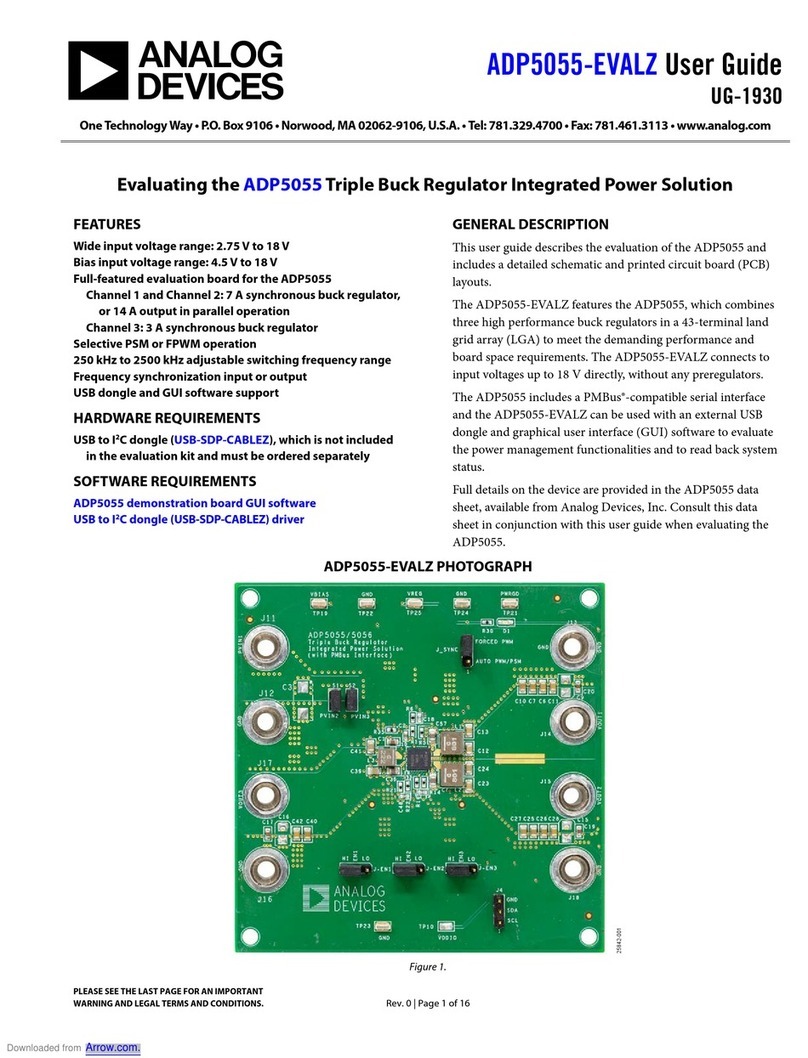
Analog Devices EVAL-ADIN1200 User manual

Analog Devices

Analog Devices EVAL-ADIN1200 User manual

Analog Devices EVAL-SSM2311 User manual

Analog Devices

Analog Devices EVAL-SSM2311 User manual

Analog Devices UG-059 User manual

Analog Devices

Analog Devices UG-059 User manual

Analog Devices EVAL-AD5338RDBZ User manual

Analog Devices

Analog Devices EVAL-AD5338RDBZ User manual

Analog Devices EVAL-AD5679RSDZ User manual

Analog Devices

Analog Devices EVAL-AD5679RSDZ User manual

Analog Devices EVAL-FLTR-DF-1RZ Installation and operating instructions

Analog Devices

Analog Devices EVAL-FLTR-DF-1RZ Installation and operating instructions

Analog Devices DC1198B-A Quick setup guide

Analog Devices

Analog Devices DC1198B-A Quick setup guide

Analog Devices EZ-KIT Lite ADSP-BF707 User guide

Analog Devices

Analog Devices EZ-KIT Lite ADSP-BF707 User guide

Analog Devices ADP2442-EVALZ User manual

Analog Devices

Analog Devices ADP2442-EVALZ User manual

Analog Devices EVAL-AD7276SDZ User manual

Analog Devices

Analog Devices EVAL-AD7276SDZ User manual

Analog Devices EVAL-CN0369SDPZ User manual

Analog Devices

Analog Devices EVAL-CN0369SDPZ User manual

Analog Devices UG-012 User manual

Analog Devices

Analog Devices UG-012 User manual

Analog Devices EV-ADF5904SD2Z User manual

Analog Devices

Analog Devices EV-ADF5904SD2Z User manual

Analog Devices ADSP-21161N User manual

Analog Devices

Analog Devices ADSP-21161N User manual

Analog Devices EVAL-AD5423SDZ User manual

Analog Devices

Analog Devices EVAL-AD5423SDZ User manual

Analog Devices ADSP-21160 EZ-KIT Lite User manual

Analog Devices

Analog Devices ADSP-21160 EZ-KIT Lite User manual

Analog Devices EVAL-ADG788EBZ User manual
Analog Devices

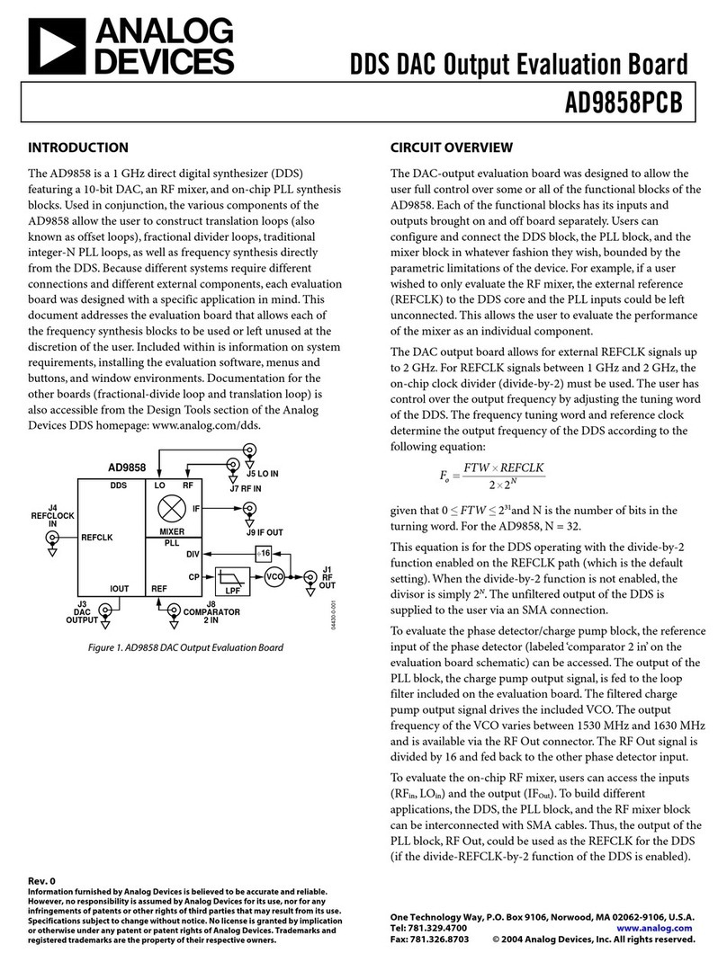
Analog Devices EVAL-ADG788EBZ User manual

Analog Devices EVAL-ADF4156EBZ1 User manual

Analog Devices

Analog Devices EVAL-ADF4156EBZ1 User manual

Analog Devices EVAL-SSM3582Z User manual

Analog Devices

Analog Devices EVAL-SSM3582Z User manual

Analog Devices AD8209A-EVALZ User manual

Analog Devices

Analog Devices AD8209A-EVALZ User manual

Analog Devices Linear Technology DC2668A Quick setup guide

Analog Devices

Analog Devices Linear Technology DC2668A Quick setup guide

Analog Devices EVAL-AD4858FMCZ User manual

Analog Devices

Analog Devices EVAL-AD4858FMCZ User manual

Analog Devices MICROCONVERTER ADUC7020 User manual

Analog Devices

Analog Devices MICROCONVERTER ADUC7020 User manual

Analog Devices EVAL-AD5693RSDZ User manual

Analog Devices

Analog Devices EVAL-AD5693RSDZ User manual

Popular Motherboard manuals by other brands

Asus H97M-PLUS manual

Asus

Asus H97M-PLUS manual

ASROCK PHANTOM GAMING Z790M PC LIGHTNING/D4 user manual

ASROCK

ASROCK PHANTOM GAMING Z790M PC LIGHTNING/D4 user manual

AXIOMTEK SBC84820 Series user manual

AXIOMTEK

AXIOMTEK SBC84820 Series user manual

ST STM32100B-EVAL user manual

ST

ST STM32100B-EVAL user manual

Advantech AIMB-258 user manual

Advantech

Advantech AIMB-258 user manual

EPH Controls R27-HW installation instructions

EPH Controls

EPH Controls R27-HW installation instructions

STMicroelectronics STEVAL-ILL028V1 user manual

STMicroelectronics

STMicroelectronics STEVAL-ILL028V1 user manual

Gigabyte MB10-DS1 user guide

Gigabyte

Gigabyte MB10-DS1 user guide

Mitsubishi Electric Hurricane HU430 user guide

Mitsubishi Electric

Mitsubishi Electric Hurricane HU430 user guide

Texas Instruments LMX1906-SP user guide

Texas Instruments

Texas Instruments LMX1906-SP user guide

ASROCK IMB-1233-WV user manual

ASROCK

ASROCK IMB-1233-WV user manual

MSI 890FXA-GD70 series user guide

MSI

MSI 890FXA-GD70 series user guide

ASROCK 775i65G user manual

ASROCK

ASROCK 775i65G user manual

Fujitsu D3488 Technical description

Fujitsu

Fujitsu D3488 Technical description

Ublox C102-F9R user guide

Ublox

Ublox C102-F9R user guide

Beckhoff EtherCAT EL9800 installation guide

Beckhoff

Beckhoff EtherCAT EL9800 installation guide

Biostar M7VIW-D Bios setup manual

Biostar

Biostar M7VIW-D Bios setup manual

Avalue Technology ENX-PNV user manual

Avalue Technology

Avalue Technology ENX-PNV user manual

manuals.online logo
manuals.online logoBrands
  • About & Mission
  • Contact us
  • Privacy Policy
  • Terms and Conditions

Copyright 2025 Manuals.Online. All Rights Reserved.