ANALOX Ax 50 User manual

Analox Ltd.
15 Ellerbeck Court, Stokesley Business Park
North Yorkshire, TS9 5PT, UK
T: +44 (0)1642 711400 F: +44 (0)1642 713900
This support line is closed on UK public holidays
Ax 50™
Carbon Dioxide Analyser
*** WARNING ***
Please read the safety information on
Pages 9 and 24 before installing this product.


Analox 50 – Carbon Dioxide Analyser – User Manual
Document Ref: A50-811-19 – September 2014
Page 2
How to fit an Ax 50TM
2
450mm
1

Analox 50 – Carbon Dioxide Analyser – User Manual
Document Ref: A50-811-19 – September 2014
Page 3
3
4

Analox 50 – Carbon Dioxide Analyser – User Manual
Document Ref: A50-811-19 – September 2014
Page 4
5
6

Analox 50 – Carbon Dioxide Analyser – User Manual
Document Ref: A50-811-19 – September 2014
Page 5
7
8

Analox 50 – Carbon Dioxide Analyser – User Manual
Document Ref: A50-811-19 – September 2014
Page 6
Ax 50TM Accessories
b
h
g
e c
i
a

Analox 50 – Carbon Dioxide Analyser – User Manual
Document Ref: A50-811-19 – September 2014
Page 7
Effects of Carbon Dioxide
1,000ppm
(0.1%)
5,000ppm
(0.5%)
10,000ppm
(1%)
15,000ppm
(1.5%)
20,000ppm
(2%)
30,000ppm
(3%)
40,000-
50,000ppm
(4-5%)
50,000-
100,000ppm
(5-10%)
100,000-
1,000,000ppm
(10-100%)
For a more detailed outline of the dangers of CO2, please visit our

Analox 50 – Carbon Dioxide Analyser – User Manual
Document Ref: A50-811-19 – September 2014
Page 8
LIST OF CONTENTS
1. SAFETY NOTES ......................................................................................9
2. PACKAGING CONTENTS CHECK ..........................................................9
3. ABOUT THE Ax 50TM..............................................................................10
3.1. BATTERY BACK-UP ENDURANCE................................................11
4. INSTALLATION ......................................................................................12
4.1. Wall Mounting..................................................................................12
4.2. Remote Alarm Repeaters ................................................................13
4.2.1. To connect a “Hard Wired” Remote Alarm Repeater................13
4.2.2. To connect a “Quick Connect” Remote Alarm Repeater ..........14
4.2.3. To connect a “Strobe LED” Remote Alarm Repeater ...............14
4.3. Alarm Relay Output Models.............................................................15
4.4. Relay Wiring ....................................................................................16
4.5. 4 to 20mA output models.................................................................17
4.6. Cleaning ..........................................................................................17
5. OPERATION...........................................................................................18
5.1. Operation at Altitude........................................................................18
6. ALARM INDICATIONS ...........................................................................18
6.1. Lamp and Alarm Test ......................................................................19
6.2. Fault Conditions...............................................................................20
7. TECHNICAL SPECIFICATIONS.............................................................21
8. WARRANTY INFORMATION .................................................................22
9. DISPOSAL..............................................................................................23
10. SAFETY..................................................................................................24
11. DECLARATION OF CONFORMITY .......................................................25

Analox 50 – Carbon Dioxide Analyser – User Manual
Document Ref: A50-811-19 – September 2014
Page 9
1. SAFETY NOTES
Every gas monitor installation should be risk assessed. The correct
location of monitor(s) must consider the potential sources of gas leaks
and the location of expected human occupation in the area. Where
large areas must be monitored, it is often advised that no single monitor
should cover a volume in excess of 80m3. The installation of more
monitors should be considered where an area is complex in shape, filled
with obstacles, has a lack ventilation or air circulation, or if there are
dead zones where gas can collect
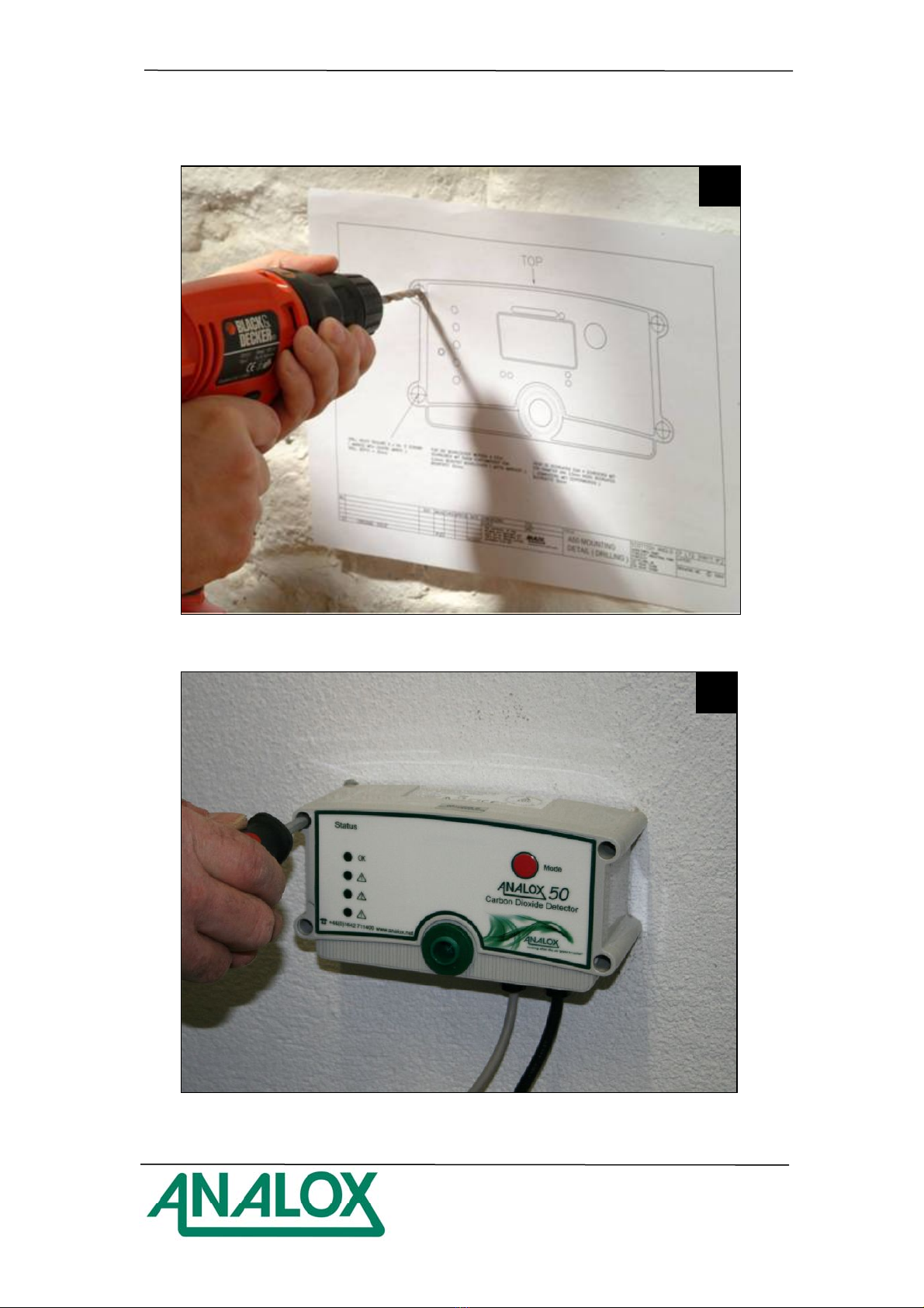
a) The Ax 50TM must be installed according to these instructions which
should be read entirely before commencing installation.
b) For your convenience the Remote Alarm Repeater is pre-wired to the
Ax 50TM sensor unit.
c) If you need to disconnect the cable for ease of installation.
DISCONNECT FROM THE REMOTE ALARM REPEATER END
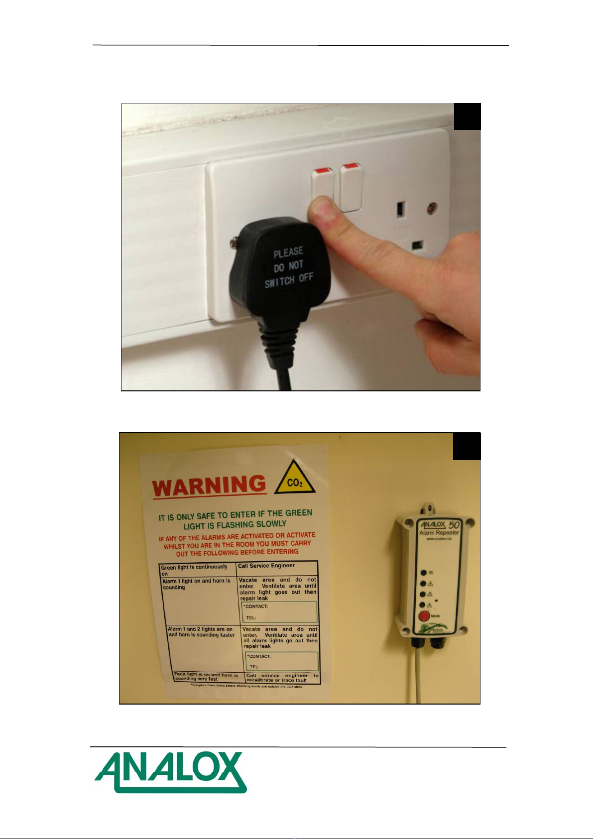
d) The system MUST NOT be switched on until all connections have been
correctly made.
e) We do not recommend you access the main unit. Potentially lethal
voltages exist within the Ax 50TM. It should only be opened by a
Qualified Technician, and must be isolated from the electrical supply
before opening.
f) The Ax 50TM does not require routine maintenance. All you need to do
is check that the green light is flashing and press the mode button
periodically to make sure that the Horn and alarm lights are functioning.
2. PACKAGING CONTENTS CHECK
The following items are enclosed:
a) Ax 50TM main unit, with power lead to a plug (where necessary)
b) User manual for standard Ax 50TM
c) Test certificate
d) Rawl plugs and screws for wall mounting
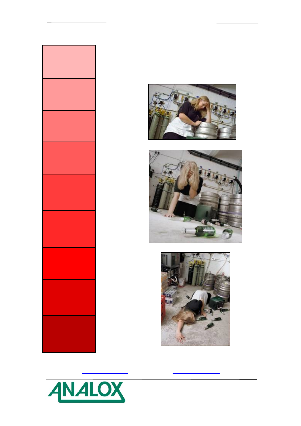
e) Remote Alarm Repeater and 8 metres of interconnecting cable
connected to the Ax 50TM.
f) Warning label

Analox 50 – Carbon Dioxide Analyser – User Manual
Document Ref: A50-811-19 – September 2014
Page 10
3. ABOUT THE Ax 50TM
The Ax 50TM unit is designed to detect the presence of Carbon Dioxide in
ambient air for the protection of people in confined spaces. The Ax 50TM
provides audible and visual indication of potentially dangerous levels of
Carbon Dioxide in the air surrounding the instrument. The instrument
uses an Infra Red detector system, together with state of the art
technology. It is housed in an IP65 splash proof enclosure, and is
designed to provide long, trouble free service, with minimum
maintenance. The Remote Alarm Repeater mimics the status indicators
on the main Ax 50TM. It also provides a push-button which operates in
the same manner as the Mode switch on the Ax 50TM.
If you have more than one entrance to your cellar or store room you may
need more than one Remote Alarm Repeater. Up to three repeaters can
be daisy chained (one repeater linked to another) covering up to three
entrance doors.
Optional items fitted to, or supplied with the unit may include the
following (as shown in the photographs on Page 6):
a) Extra Remote Alarm Repeaters
b) Oxygen sensor*
c) Medium duty relays*
d) 4 to 20mA current loop output (or 0-1V)*
e) Battery back-up*
f) 4 digit display*
g) Remote Alarm Repeater with high intensity strobe beacon*
h) Splash guard
i) Calibration gasses
* Please note these items cannot be retro fitted.

Analox 50 – Carbon Dioxide Analyser – User Manual
Document Ref: A50-811-19 – September 2014
Page 11
3.1. BATTERY BACK-UP ENDURANCE
If fitted the Battery back-up will give the Ax 50TM between 7 and 14 hours
normal operation in the event of a power failure, some examples are
listed below:
Instrument Type Battery Back-up Endurance
Standard Ax 50TM with 1 Remote Alarm 14 Hours
Ax 50TM including 4-20mA Output, 1 Relay
Output and 2 Remote Alarms
11 Hours
Ax 50TM including 4-20mA Output, 2 Relay
Outputs and 2 Remote Alarms
7 Hours
In normal operating conditions using an external power source (Mains
AC or DC) the Battery Back-up should last up to approximately 5 years
or 200 cycles.

Analox 50 – Carbon Dioxide Analyser – User Manual
Document Ref: A50-811-19 – September 2014
Page 12
4. INSTALLATION
4.1. Wall Mounting
The power socket that the equipment plugs into must be positioned so
that it is close to the equipment and in easy reach of the operator.
If the power supply for the Ax 50TM is not positioned so that it is close to
the equipment and in easy reach of the operator, a local means of
double pole isolation must be provided. Isolation can be achieved either
by means of a non-locking plug or a double pole switch of suitable rating.
A label must be placed by the local disconnection point for the Ax 50TM
stating
"REMOVE PLUG TO DISCONNECT Ax 50TM"
The Ax 50TM should be mounted onto a wall using the mounting lugs on
the unit. Rawl plugs and screws are provided for this purpose. It is not
necessary to dismantle the Ax 50TM main unit in any way prior to
installation. You need to ensure the mains plug fused at 5amp is in easy
reach of a power socket.
Attach the main unit to the wall 450mm from the floor as close to the
valves and manifolds as possible. An 8 metre 8 core cable is pre-wired
to the Ax 50TM and has a Remote Alarm Repeater pre-attached. Run the
Remote Alarm Repeater cable to the outlet door, safely securing the
cable with cable clips.
A drilling template is included with this booklet.

Analox 50 – Carbon Dioxide Analyser – User Manual
Document Ref: A50-811-19 – September 2014
Page 13
4.2. Remote Alarm Repeaters
The Remote Alarm Repeater should be located at eye level and
attached to the outside or immediately inside the access door. If you
need to disconnect the Remote Alarm Repeater, reconnection is in one
of the following ways:-
4.2.1. To connect a “Hard Wired” Remote Alarm Repeater
1) Disconnect the power supply from the Ax 50TM.
2) Open the Remote Alarm Repeater unit by removing the 4 screws
in the front of the case and carefully pulling the case apart. The
connecting wires from the Ax 50TM pass through one of the cable
glands on the Remote Alarm Repeater.
3) Terminate the wires in accordance with the table below
4) Replace the lid of the Remote Alarm Repeater, insert and tighten
the 4 screws, and mount it in the desired position using the 2
fixing lugs.
5) Restore power to the Ax 50TM. Press the switch on the Remote
Alarm Repeater once, and ensure that the four indicators flash.
Note that in the presence of a genuine alarm, this test feature is
disabled.
REPEATER CABLE COLOURS Ax 50
Type 1 Repeater
Term Type 2 (Cat 5) ST1
Terminal
No
8 3
7 2
6 4
5 5
4 6
3 7
2 8
1 1

Analox 50 – Carbon Dioxide Analyser – User Manual
Document Ref: A50-811-19 – September 2014
Page 14
4.2.2. To connect a “Quick Connect” Remote Alarm Repeater
1) Disconnect the power supply from the Ax 50TM.
2) Insert the connector on the end of the wire into either socket on
the bottom of the Remote Alarm Repeater.
3) Restore power to the Ax 50TM. Press the switch on the Remote
Alarm Repeater once, and ensure that the four indicators flash.
Note that in the presence of a genuine alarm, this test feature is
disabled.
4.2.3. To connect a “Strobe LED” Remote Alarm Repeater
1) Disconnect the power supply from the Ax 50TM.
2) Open the Remote Alarm Repeater unit by removing the 4 screws
in the front of the case and carefully pulling the case apart. The
connecting wires from the Ax 50TM pass through one of the cable
glands on the Remote Alarm Repeater.
3) Terminate the wires in accordance with the table below
4) For units NOT fitted with internal relay(s): Connect the free wire
(Brown or Orange) to A50-231 main PCB at JP13 terminal 5.
For units fitted with internal relay(s): Connect the free wire (Brown
or Orange) to A50-231 main PCB at IC10 terminal 2 and move the
wire from terminal 4 (Green/white or green) to terminal 2 of ST1.
5) Replace the lid of the Remote Alarm Repeater, insert and tighten
the 4 screws, and mount it in the desired position using the 2
fixing lugs.
REPEATER CABLE COLOURS Ax 50
Type 1 Repeater
Term Type 2 (Cat 5) ST1
Terminal
No
8 3
7 *See
Note 4
6 4
5 5
4 6
3 7
2 8
1 1

Analox 50 – Carbon Dioxide Analyser – User Manual
Document Ref: A50-811-19 – September 2014
Page 15
6) Restore power to the Ax 50TM. Press the switch on the Remote
Alarm Repeater once, and ensure that the four indicators and the
LED strobe flash. Note that in the presence of a genuine alarm,
this test feature is disabled.
4.3. Alarm Relay Output Models
You may have ordered your Ax 50TM with relays (only 1 relay available if
O2 sensor specified). Relays are available in 2 different formats as
follows:
Internal relays
The relays are fitted internal to the main unit with a pre-wired 1m 6-core
cable supplied connected to relay contacts. With all power isolated,
make wiring connections to the Relay cable.
The relay contacts are ‘Volt-Free’ single pole Changeover and are rated
50VAC/DC, 1 Amps (max).
External relays
A pre-wired junction box is supplied with the Ax 50TM main sensor unit.
There is no need to open the main sensor unit. With all power isolated,
make wiring connections to the Relay Terminal Box.
The relay contacts are ‘Volt-Free’ single pole Changeover and are rated
240VAC/28VDC, 2 Amps (max).
For either internal or external the relays are normally non-latching which
means the relays will only activate when an alarm is raised and
deactivate when the alarm cancels.
Latched versions are available; if relays are latched they will only cancel
once the alarm state has cleared, and the mode switch on the Ax 50TM or
Remote Alarm Repeater is pressed.
The relays are normally supplied ‘Fail Safe’ i.e. normally energised, and
will de-energise when in alarm state. The relay will also be in its alarm
state during the forty second warm up period.

Analox 50 – Carbon Dioxide Analyser – User Manual
Document Ref: A50-811-19 – September 2014
Page 16
4.4. Relay Wiring
Internal relays
Ensure that the load is within the limits of the relay, 50VAC/DC, 1 Amps
(max).
External relays
The cable gland is for cables of outside diameter between 5 and 7mm, if
cable fitted is outside that range, a suitably specified cable gland must
be used. Ensure that the gland is properly tightened. Test that the cable
is adequately gripped by the cable gland. Ensure that the cable is
suitable for purpose, the load is within the limits of the relay,
240VAC/28VDC, 2Amps, and the insulation of the external circuit meets
the requirements for basic insulation 240VAC/28VDC, 2 Amps. After
completing wiring, ensure that the terminal box cover is securely
replaced.
RELAY TERMINAL BOX TERMINATIONS
Cable core Relay terminals
Relay 1 COM
Relay 1 N.O.
Relay 1 N.C.
Relay 2 COM
Relay 2 N.O.
Relay 2 N.C.

Analox 50 – Carbon Dioxide Analyser – User Manual
Document Ref: A50-811-19 – September 2014
Page 17
SIMPLIFIED RELAY WIRING DIAGRAM
4.5. 4 to 20mA output models
You may have ordered your Ax 50™ with a 4 to 20mA output. A 2m cable is
factory fitted to the instrument. The 4 to 20mA output current is generated by
the instrument. The customer system should be connected to this cable as
follows and as per the following drawing:
1) Blue wire 4 to 20mA negative
2) Red wire 4 to 20mA positive
(Max load 150 Ω)
4.6. Cleaning
All parts of the Ax 50TM may be cleaned with a soft cloth, moistened with
water.

Analox 50 – Carbon Dioxide Analyser – User Manual
Document Ref: A50-811-19 – September 2014
Page 18
5. OPERATION
When mains power is first applied to the Ax 50TM, it requires a period of
approximately 40 seconds to stabilise. During this period, The
‘Good/OK’ and ‘Fault’ status indicators will be turned on. The ‘Good/OK’
status indicator will flash briefly every few seconds, indicating normal
operation and after the initial stabilising period has expired, the ‘Fault’
status indicator will turn off. The Ax 50TM will then be in its normal
operating condition. During normal operation, the ‘Good/OK’ green light
will flash on/off, thus indicating that the system is operating correctly.
The green light status indicator on any Remote Alarm Repeaters will
also flash on and off.
5.1. Operation at Altitude
The toxic effects of Carbon Dioxide are dependent on the partial
pressure, or the quantity of gas molecules, not the percentage in the
atmosphere; therefore at altitudes above 900 metres (3000 feet) alarms
will operate below the factory calibration point. Please refer to our
website www.analox.net for details of suitable alarm set points and
calibration procedures at altitude.
6. ALARM INDICATIONS
Standard unit
If the Ax 50TM detects a Carbon Dioxide concentration which exceeds
the first alarm level, then the red First Alarm indicator will begin to flash
and the Horn will sound.
If the measured concentration of Carbon Dioxide continues to rise above
the second alarm level, then the red Second Alarm indicator will also
begin to flash and the pace of the Horn will increase. This condition will
be repeated on any Remote Alarm Repeaters. The alarms are self-
cancelling when the Carbon Dioxide level falls below the alarm limits.
Alternatively latched alarm versions are available, on which the Ax 50TM
will stay in the alarm mode until the gas concentration has fallen below
the alarm set point and the mode switch has been pressed to accept the
alarm.
Alarm 1
Alarm 2

Analox 50 – Carbon Dioxide Analyser – User Manual
Document Ref: A50-811-19 – September 2014
Page 19
Pre-alarm unit
If the Ax 50TM has a 0.5% pre-alarm and it detects a Carbon Dioxide
concentration which exceeds this first alarm level, then the red First
Alarm indicator will begin to flash but the Horn will not sound.
If the measured concentration of Carbon Dioxide continues to rise above
the second alarm level, then the red Second Alarm indicator will also
begin to flash and the Horn will sound. This condition will be repeated on
any Remote Alarm Repeaters. The alarms are self-cancelling when the
Carbon Dioxide level falls below the alarm limits.
If the measured concentration of Carbon Dioxide continues to rise above
the third alarm level, then the red third Alarm indicator will also begin to
flash and the pace of the Horn will increase. This condition will be
repeated on any Remote Alarm Repeaters. The alarms are self-
cancelling when the Carbon Dioxide level falls below the alarm limits.
Alarm 1
(Pre alarm)
Alarm 2
Alarm 3
6.1. Lamp and Alarm Test
Momentarily pressing the ‘Mode’ button on either the Ax 50TM or any
Remote Alarm Repeaters, in the absence of any alarm conditions,
causes a lamp and alarm test to be performed. The indicator lamps will
flash 4 times, together with the alarm Horn. This test should be carried
out each time the area is entered.
Please note that the optional relays which may be fitted to the
instrument are NOT operated during this test. Therefore any lights or
sirens which may be connected to the instrument will NOT be tested
by this operation.
Table of contents
Other ANALOX Analytical Instrument manuals