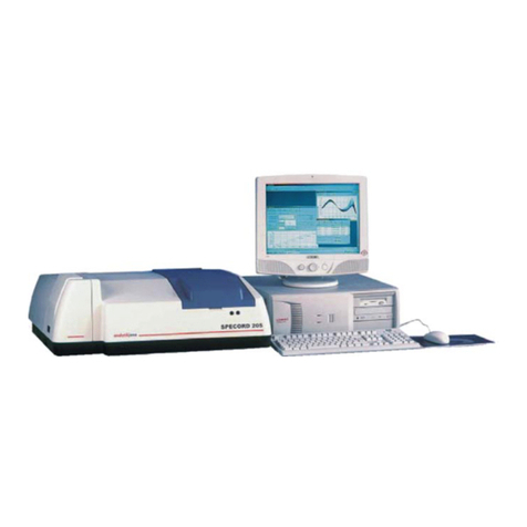
Analytik Jena SPECORD 200 User manual

Accessories
UV VIS Spectrophotometer
SPECORD®200 / 205 / 210 / 250

Analytik Jena AG
Kundendienst
Konrad-Zuse-Str. 1
07745 Jena
Phone: Hotline: + 49 (3641) 77-7407
Fax: + 49 (3641) 77-7449
General information about Analytik Jena AG
on the internet: http://www.analytik-jena.de
Copyrights and Trademarks
Microsoft, Windows 2000, Windows XP, Windows NT, MS Excel are registered trademarks of Microsoft
Corp.
Publication No.: 221:426.23
Edition – July 2005
Technical documentation made by:
Analytik Jena AG
This documentation describes the state of this product at the time of publishing. It
need not necessarily agree with future versions of the product.
Subject to change!
© Copyright 2005 Analytik Jena AG

Contents
Contents
1Introduction .....................................................................5
1.1 Safety notes .....................................................................................................6
1.2 Care of accessories..........................................................................................7
1.3 Basics of SPECORD alignment........................................................................7
1.3.1 Sample compartment of SPECORD®...............................................................7
1.3.2 Adjustment of zeroth order...............................................................................8
1.3.3 Changing the position of the carrying rails .......................................................8
2Universal holder ............................................................11
2.1 Description and use........................................................................................11
2.2 Description .....................................................................................................11
2.3 Using the universal holder..............................................................................12
3100 mm cylindrical cell (absorption tube)...................13
3.1 Description and use........................................................................................13
3.2 Description .....................................................................................................13
3.3 Inserting the 100mm cylindrical cell................................................................13
3.4 Care and transportation of cylindrical cell.......................................................14
4Solid sample holder ......................................................15
4.1 Description and use........................................................................................15
4.2 Using the holder and inserting the sample.....................................................15
5Holder for cylindrical cells............................................17
5.1 Description and use........................................................................................17
5.2 Description .....................................................................................................17
5.3 Using the holder for cylindrical cells...............................................................17
6Holder for round cells...................................................19
6.1 Description and use........................................................................................19
6.2 Description .....................................................................................................19
6.3 Using the holder for round cells......................................................................19
7Holder for semi-microcells and microcells.................21
7.1 Description and use........................................................................................21
7.2 Holder for semi-microcells..............................................................................21
7.3 Adjustable holder for microcells, non-thermostatted, (8.5 mm / 15 mm beam
height)............................................................................................................22
7.4 Adjustable holder for microcells, non-thermostatted (8.5 mm beam height)...23
8Thermostatted cell holder.............................................25
8.1 Description and use........................................................................................25
8.2 Description .....................................................................................................25
8.3 Using the thermostatted cell holder................................................................25
8.3.1 Connection and installation in sample compartment......................................25
User’s Manual SPECORD®200/205/210/250 – Accessories 07/2005 1
Analytik Jena AG

Contents
8.3.2 Inserting the magnetic stirrer..........................................................................26
9Adjustable cell holder, thermostatted .........................29
9.1 Inserting the cell.............................................................................................30
9.2 Aligning the cell..............................................................................................30
10 6-cell changer, thermostatted ......................................31
10.1 Description and use........................................................................................31
10.2 Design............................................................................................................32
10.3 Installation and insertion in sample compartment...........................................33
10.3.1 Installation of magnetic stirrers.......................................................................33
10.3.2 Connection to a thermostat ............................................................................34
10.3.3 Installation in sample compartment................................................................35
10.4 Operation .......................................................................................................36
10.4.1 Settings in Measurement Parameters window...............................................36
10.4.2 Measurements with the 6-cell changer...........................................................38
10.4.3 Operating modes of cell changers..................................................................38
11 8-cell changer................................................................41
11.1 Removal of transport lock on non-temperature-controlled 8-cell changer......41
11.2 Design of 8-cell changer.................................................................................42
11.3 Installation of 8-cell changer...........................................................................42
11.4 Operation of the 8-cell changer......................................................................44
11.4.1 Software settings............................................................................................44
11.4.2 Measurements with the 8-cell changer...........................................................45
11.5 Use of two 8-cell changers.............................................................................45
11.5.1 Staggered operation of two 8-cell changers for more than 8 samples............46
11.5.2 Synchronous operation of two 8-cell changers...............................................47
12 Cell carousel..................................................................49
12.1 Description and use........................................................................................49
12.2 Design............................................................................................................49
12.3 Installation in sample compartment................................................................50
12.4 Operation .......................................................................................................51
13 Peltier temperature-controlled cell holders/cell
changers ........................................................................53
13.1 Peltier temperature-controlled cell holder, air-cooled.....................................54
13.1.1 Safety notes ...................................................................................................55
13.1.2 Technical data of Peltier temperature-controlled cell holder, air-cooled.........56
13.1.3 Design of Peltier-temperature-controlled cell holder, air-cooled.....................57
13.1.4 Installation of Peltier temperature-controlled cell holder in SPECORD®.........58
13.1.5 Care ...............................................................................................................60
13.2 Peltier temperature-controlled cell holder with heat exchanger......................62
2 User’s Manual SPECORD 200/205/210/250 – Accessories 07/2005
Analytik Jena AG
Contents
13.2.1 Safety notes for the use of the Peltier temperature-controlled cell holder with
heat exchanger...............................................................................................62
13.2.2 Technical data of Peltier temperature-controlled cell holder with heat
exchanger ......................................................................................................64
13.2.3 Design of Peltier temperature-controlled cell holder with heat exchanger......66
13.2.4 Installation of the cell holder in the SPECORD®.............................................66
13.3 Peltier temperature-controlled 6-cell changer.................................................69
13.3.1 Use.................................................................................................................69
13.3.2 Safety notes ...................................................................................................70
13.3.3 Technical data of Peltier temperature-controlled 6-cell changer ....................71
13.3.4 Design of Peltier temperature-controlled 6-cell changer.................................73
13.3.5 Installation of the Peltier-temperature-controlled 6-cell changer ....................74
13.3.6 Settings in WinASPECT®software.................................................................77
13.3.7 Measurement procedure ................................................................................78
13.4 Peltier temperature-controlled 8-cell changer.................................................79
13.4.1 Safety notes ...................................................................................................80
13.4.2 Technical data of Peltier temperature-controlled 8-cell changer ....................81
13.4.3 Design of Peltier temperature-controlled 8-cell changer.................................83
13.4.4 Installation of Peltier temperature-controlled 8-cell changer...........................84
13.4.5 Settings in WinASPECT®software.................................................................88
13.4.6 Measurement procedure ................................................................................89
13.5 Connection and operation of temperature control unit....................................90
13.5.1 Connecting the temperature control unit ........................................................90
13.5.2 Settings on temperature control unit...............................................................91
13.5.3 Replacing fuses on the temperature control unit............................................93
13.6 Connection and operation of the heat exchanger...........................................94
13.6.1 Preparing the coolant .....................................................................................94
13.6.2 Connecting the heat exchanger......................................................................94
13.6.3 Replacing fuses on the heat exchanger.........................................................95
14 Cassette sipper..............................................................97
14.1 Intended use ..................................................................................................97
14.2 Design of cassette sipper...............................................................................97
14.3 Mounting the cassette sipper .........................................................................98
14.3.1 Mounting the tube set.....................................................................................98
14.3.2 Mounting the sipper in the sample compartment............................................99
14.3.3 Adjusting the flow cell...................................................................................100
14.4 Sample measurement ..................................................................................101
14.4.1 Settings on the PC .......................................................................................101
14.4.2 Performing a sample measurement .............................................................102
14.5 Care and maintenance.................................................................................103
User’s Manual SPECORD®200/205/210/250 – Accessories 07/2005 3
Analytik Jena AG

Contents
15 APG 53/100 XYZ Autosampler....................................105
15.1 Intended use ................................................................................................105
15.2 Safety notes .................................................................................................105
15.3 Design and installation of the APG 53/100...................................................106
15.4 Connecting the XYZ autosampler to the SPECORD®..................................108
15.5 Sample measurement ..................................................................................110
15.6 Finding the appropriate pump time...............................................................111
16 Fiber coupling for measuring probes........................113
16.1 Description and use......................................................................................113
16.2 Design and function of fiber coupling with measuring probe ........................113
16.3 Design and function of the fiber coupling with SMA connectors...................114
16.4 Installation of the adapter in the sample compartment.................................114
16.5 Alignment of fiber coupling...........................................................................114
17 Absolute Reflectance Attachment .............................115
17.1 Description and use......................................................................................115
17.2 Design..........................................................................................................115
17.3 Installation in sample compartment..............................................................116
17.4 Operating principle.......................................................................................116
17.5 Adjustment ...................................................................................................117
17.6 Measurements with the Absolute Reflectance Attachment ..........................117
17.7 Care and maintenance.................................................................................118
18 Variable Angle Reflectance Attachment....................119
18.1 Description and use......................................................................................119
18.2 Design and operating principle.....................................................................119
18.3 Installation in sample compartment..............................................................121
18.4 Adjusting the angle of reflection ...................................................................121
18.5 Measuring with the reflectance attachment..................................................121
18.6 Calculating the reflectance...........................................................................121
18.7 Calculating pathlength and refractive index..................................................122
18.8 Care and maintenance.................................................................................123
18.9 Technical data..............................................................................................123
19 Integrating Sphere.......................................................125
19.1 Description and use......................................................................................125
19.2 Design of integrating sphere ........................................................................126
19.3 Measurements with the integrating sphere...................................................127
19.4 Transmittance measurements......................................................................127
19.5 Reflectance measurements..........................................................................129
19.6 Technical Data .............................................................................................133
20 Figures .........................................................................135
4 User’s Manual SPECORD 200/205/210/250 – Accessories 07/2005
Analytik Jena AG
Introduction
Safety notes
1 Introduction
This manual contains the description of the following devices
• SPECORD®200, from S/N 222 U (or V W X) 100
• SPECORD®205
• SPECORD®210
• SPECORD®250.
If the descriptions equally refer to all three models, only the collective term SPECORD®
will be used.
In this manual, the following symbols are used to refer you to warnings and notes:
Danger!
Danger messages must be strictly observed to prevent personal injury.
Caution!
Caution messages refer you to procedures which, if not observed, could result in damage
to the equipment.
Warning! Dangerous electric voltage!
Warning! Emission of UV radiation!
Disconnect power cable!
Note
This note must be followed to obtain correct measurement results.
For easier navigation within the manual, the manual uses the following system:
• Chapters and illustrations are numbered consecutively.
• Every illustration has its own caption.
• Steps of operation are consecutively numbered.
• Cross-references are marked by an arrow, e.g. →Section "Introduction" p. 1.
User’s Manual SPECORD 200/205/210/250 – Accessories 07/2005 5
Analytik Jena AG

Introduction
Safety notes
1.1 Safety notes
Handling of the accessories is subject to the safety instructions given for the SPECORD®
basic unit (→User's Manual SPECORD®, Section Safety Notes).
For all accessories of the SPECORD®Series, the following safety instructions are
applicable:
Intended use!
The SPECORD®, including original accessories, may only be used for the applications
described in this manual. The manufacturer cannot assume any liability for any other
application, including that of individual modules or single parts. This also applies to all
service or repair work that is not carried out by authorized service personnel. All
warranty claims shall be forfeited.
Transportation and storage!
Accessories not in use should always be stored in the provided packaging!
For transportation, always use the provided original packaging!
Risk of corrosion!
Do not set up the device near aggressive vapors, e.g. strongly corrosive acid or caustic
vapors! The vapors might corrode the connections, mechanical and optical components
of the device.
Avoid exposing the sample compartment and the accessories to strongly corrosive
substances! For the analysis of such samples, use vapor-tight stoppered cells.
Observe specific instructions!
Accessory-specific instructions are given in the chapter describing its use.
Caution! Contamination!
Never touch any optical mirrors of accessory units!
Additionally, observe the operating instructions and safety notes of any supplied system
components of other manufacturers (e.g. fluid thermostats
6 User’s Manual SPECORD 200/205/210/250 – Accessories 07/2005
Analytik Jena AG
Introduction
Care of accessories
1.2 Care of accessories
The accessories are largely maintenance-free.
The following rules apply to all accessories:
Avoid any contamination by handling sample substances carefully.
Wipe off spilt samples or reagents immediately with an absorbent cloth or cleaning
tissue.
Do not expose accessories to corrosive atmospheres to prevent corrosion.
If provided, observe the additional instructions on the care of individual accessory
units.
1.3 Basics of SPECORD alignment
1.3.1 Sample compartment of SPECORD®
1Sample beam path with two
carrying rails
2Reference beam path with two
carrying rails
3Connector for sipper and cell
changer
4Connector (reserve)
5Stopper for duct of optical fiber of
measuring probe or electrical
cables
6Duct for coolant tubes
7Receptacle for cells with turbid
samples
8Mount for cell holder
9Receptacle for cells with turbid
samples
10 Mount for cell holder
11 Duct for drain tube (not visible)
12 Ducts for sample-aspirating
tubes (sipper)
Fig. 1-1 Sample compartment
Sample (1) and reference beam (2) enter the sample compartment through the left-hand
wall.
The mounts for the cell holders (8), (10) are arranged in front of the exit windows in the
right-hand sample compartment wall.
The two pairs of carrying rails serve to accommodate the accessories, which easily
clamp to the rods.
The receptacles for the cells (7), (9) with turbid samples are located directly in front of
the detector at the right-hand sample-compartment wall.
Two 9-pin connectors (3), (4) allow the connection of electrically driven accessories,
such as the automatic temperature-controlled cell changer or the sipper system.
User’s Manual SPECORD 200/205/210/250 – Accessories 07/2005 7
Analytik Jena AG

Introduction
Basics of SPECORD alignment
The optical fibers of the measuring probe or the cables of the Peltier temperature-
controlled cell holder or the cell changer are threaded through the recess in the rear wall
of the sample compartment (5).
The three ducts (6,11) in the right-hand sample compartment wall are used for threading
through the sample drain tube and the coolant tubes for the thermostat.
The ducts in the front side of the device cover (12) are provided for threading through the
aspirating tubes of the sipper system.
1.3.2 Adjustment of zeroth order
In zeroth order adjustment, white, undispersed light passes through the sample
compartment. This high-intensity beam is particularly suitable for the alignment of
accessories.
Open the Service Check utility of WinASPECT®software by following this procedure:
1. On the Windows taskbar, click the Start button. In the Programs folder, open the
WinASPECT folder. There, click on Service xxx. This will bring up the Specord xxx
- Service Check dialog box.
2. In this dialog box, click on the Zeroth Order button and choose the halogen lamp
(HL – Lamp).
1.3.3 Changing the position of the carrying rails
1 Knurled screw 3 Adapter
2 Support in sample compartment wall 4 Carrying rail
Fig. 1-2 Carrying rails mounted in bottom position
To use the cell carousel, you have to mount the carrying rails in the bottom position. For
that, you need two adapters, which are included in the equipment of the cell carousel.
1. Unscrew one of the carrying rails in the sample beam path (front pair) and remove
the rod from the sample compartment.
2. Screw one adapter (3) onto the carrying rail.
3. Put the carrying rail onto the bottom, cone-shaped journal in the right-hand sample
compartment wall.
8 User’s Manual SPECORD 200/205/210/250 – Accessories 07/2005
Analytik Jena AG
Introduction
Basics of SPECORD alignment
4. Hold the carrying rail with adapter from the bottom against the support (2) and
fasten the carrying rail by means of the knurled screw. Fasten the knurled screw
hand-tight so that the carrying rail cannot be moved.
5. Repeat the above procedure for the second carrying rail.
User’s Manual SPECORD 200/205/210/250 – Accessories 07/2005 9
Analytik Jena AG


Universal holder
2 Universal holder
2.1 Description and use
The universal holder accommodates the following accessory units:
• Holder for 100 mm cylindrical cell
• Holder for cells of up to 50 mm pathlength
• Thermostatted cell holder for accommodation and temperature control of a
cell of up to 10 mm pathlength (may be fitted with magnetic stirrer)
• Thermostatted cell holder for accommodation and temperature control of a
cell of up to 50 mm pathlength
• Solid sample holder for accommodation of films and sample plates of up to
25 mm pathlength and a minimum diameter of ≥20 mm
• Holder for round cells
• Holder for semi-microcells and microcells
2.2 Description
1 Mounting plate for cell or solid
sample holders
2 Clamp lever
Fig. 2-1 Universal holder
User’s Manual SPECORD 200/205/210/250 – Accessories 07/2005 11
Analytik Jena AG

Universal holder
2.3 Using the universal holder
Fig. 2-2 Attaching and clamping the universal holder
1. Put the universal holder with its hook onto the rear of the carrying rails allocated to
sample or reference channel. Then, slide it to the right-hand wall of the sample
compartment as far as it will go.
2. Throw clamp lever (2) to the right to clamp the universal holder.
3. After you have attached and clamped the universal holder, slide the cell holder or
the solid sample holder onto its mounting plate.
Note
It is necessary to position the universal holder at the right-hand wall of the sample
compartment if the inserted sample shall be analyzed in the position where the beam
cross-section is minimal.
This position ensures optimum signal-to-noise ratio.
If you want to arrange the sample in a different position, you can slide the universal
holder to another place on the carrying rail and clamp it there.
You may also mount it inversely so that the plate (1) that accommodates the cell or solid
sample holder is on the left-hand side.
12 User’s Manual SPECORD 200/205/210/250 – Accessories 07/2005
Analytik Jena AG
100 mm cylindrical cell (absorption tube)
3 100 mm cylindrical cell (absorption tube)
3.1 Description and use
The cylindrical cell serves for measuring liquid samples requiring a pathlength of 100
mm. The effective pathlength of the cell (in cm) is engraved to the cell body.
The 100mm cylindrical cell comes with a special holder (1) for cylindrical cells.
3.2 Description
1 Holder for cylindrical cell 5 100mm cylindrical cell
2 Universal holder 6 Filling port with stopper
3 Clamping lever 7 Effective pathlength of the cell
4 Mounting plate of universal holder
Fig. 3-1 100 mm cylindrical cell
3.3 Inserting the 100mm cylindrical cell
1. Put the universal holder (2) with its hook onto the rear of the two front carrying rails.
Slide it to the right-hand wall of the sample compartment as far as it will go.
2. Throw clamping lever (3) over to the right to clamp the universal holder.
3. Slide holder (1) for cylindrical cells from top onto mounting plate (4) of the universal
holder.
4. Insert the 100mm cylindrical cell (5) flush right in holder (1) for cylindrical cells and
slide the complete universal holder (2) assembly to the right-hand sample
compartment wall.
User’s Manual SPECORD 200/205/210/250 – Accessories 07/2005 13
Analytik Jena AG

100 mm cylindrical cell (absorption tube)
3.4 Care and transportation of cylindrical cell
Store and carry the cylindrical cell only in the original packing.
Clean the cylindrical cell after every use.
14 User’s Manual SPECORD 200/205/210/250 – Accessories 07/2005
Analytik Jena AG

Solid sample holder
4 Solid sample holder
4.1 Description and use
The holder is suited for solids having a minimum diameter of 20 mm and a maximum
pathlength of 25 mm.
The size of samples should not exceed 80 mm x 140 mm.
1 Guide
2 Mechanical stop
3 Spring clip
4 Knurled screw
5 Support block
Fig. 4-1 Solid sample holder
4.2 Using the holder and inserting the sample
6 Sample
Fig. 4-2 Solid sample in holder slide
1. Slide the solid sample holder with its guide from top onto the mounting plate (Fig.
1-1 / 10).
2. Loosen knurled screw (4) and push support block (5) to the left stop.
3. Insert sample (6) into holder so that it rests on mechanical stop (2).
4. Push support block (5) towards the sample so that spring clips (3) safely hold the
sample.
5. Fasten knurled screw (4).
User’s Manual SPECORD 200/205/210/250 – Accessories 07/2005 15
Analytik Jena AG


Holder for cylindrical cells
5 Holder for cylindrical cells
5.1 Description and use
These holders serve for the accommodation of cylindrical cells without and with
temperature control (thermocell) having an outside diameter of 22 mm and a length of up
to 100 mm.
5.2 Description
1 Support rods for cells of up to 50 mm length
2 Support rods for cells of up to 100 mm length
Fig. 5-1 Holders for cylindrical cells
5.3 Using the holder for cylindrical cells
1 Fill-in port
2 Window
3 Connectors for thermostatting tubes
Fig. 5-2 10 mm thermocell (cylindrical)
Slide the holders from to onto the mounting plate for cell holders (Fig. 1-1 / 10).
Put the cylindrical cell onto the support rods. If the thermostatted cell is being used, the
thermostatting tubes must be threaded outside the sample compartment through the
provided holes in the same way as with the thermostatted cell holder (→see Section
“Thermostatted cell holder”).
User’s Manual SPECORD 200/205/210/250 – Accessories 07/2005 17
Analytik Jena AG

Other manuals for SPECORD 200
1
This manual suits for next models
3
Table of contents
Other Analytik Jena Measuring Instrument manuals

Analytik Jena
Analytik Jena SPECORD S600 User manual

Analytik Jena
Analytik Jena SPEKOL 2000 User manual

Analytik Jena
Analytik Jena multi EA 4000 User manual

Analytik Jena
Analytik Jena SPECORD 200 PC User manual

Analytik Jena
Analytik Jena SPECORD 50 PLUS User manual

Analytik Jena
Analytik Jena SPEKOL 1300 User manual

Analytik Jena
Analytik Jena SPECORD S600 User manual

Analytik Jena
Analytik Jena compEAct N User manual

Analytik Jena
Analytik Jena SPEKOL 1500 User manual

Analytik Jena
Analytik Jena SPECORD S600 User manual