ANDELI MCT Series User manual

OWNER'S MANUAL
MCT-520DPL PRO
MULTIFUCTION WELDING&CUTTING MACHINE

1
CONTENTS
1. BRIEF INSTRUCTION ..........................................................................................2
2. SAFETY WARNING ............................................................................................. 3
3. TECHNICAL PARAMETERS TABLE .............................................................. 4
4.Structure of welder.........................................................................5
5. INSTALLATION INSTRUCTION ...................................................................7
6. PRECAUTIONS ....................................................................................................13
7. TROUBLESHOOTING AND FAULT FINDING ......................................... 14
8. EXPLOSIVE VIEW .............................................................................................. 19

2
1. BRIEF INSTRUCTION
1.1 MCT series welding machine is the latest multi-purpose machine developed by our company. It
is suitable for all kinds of metal cutting machines, argon arc welding and manual arc welding. Its
biggest feature is that it can cut stainless steel, alloy steel, carbon steel, and other non-ferrous
metals with cutting function, or it can weld stainless steel and carbon steel products with DC
function. For example: for the welding of scooters, bicycles and other products.
1.2 MCT series welding machine is also based on our company's unique high-frequency inverter
technology, compared with the traditional machine, small size, light weight, high conversion
efficiency, energy saving; Compared with imported machine, cheaper, more adaptable to power
grid. To highlight the use of two inverter technology, the pure square wave output, so that the arc
stiffness is good, heat concentration, reverse cleaning ability, wide cleaning range, small current
is not easy to break the arc, etc., to ensure the excellent welder Welding characteristics.
1.3 The welding machine is also equipped with a foot pedal current regulating device, so that the
welder can free the hand to adjust the current with the foot; thus, the current can be quickly
heated when the welding is initial and the wire is added, and the current is reduced at the end of
the welding. Welding pattern formation; the use of the pedal helps to improve welding efficiency,
reduce welding difficulty and ensure welding quality.
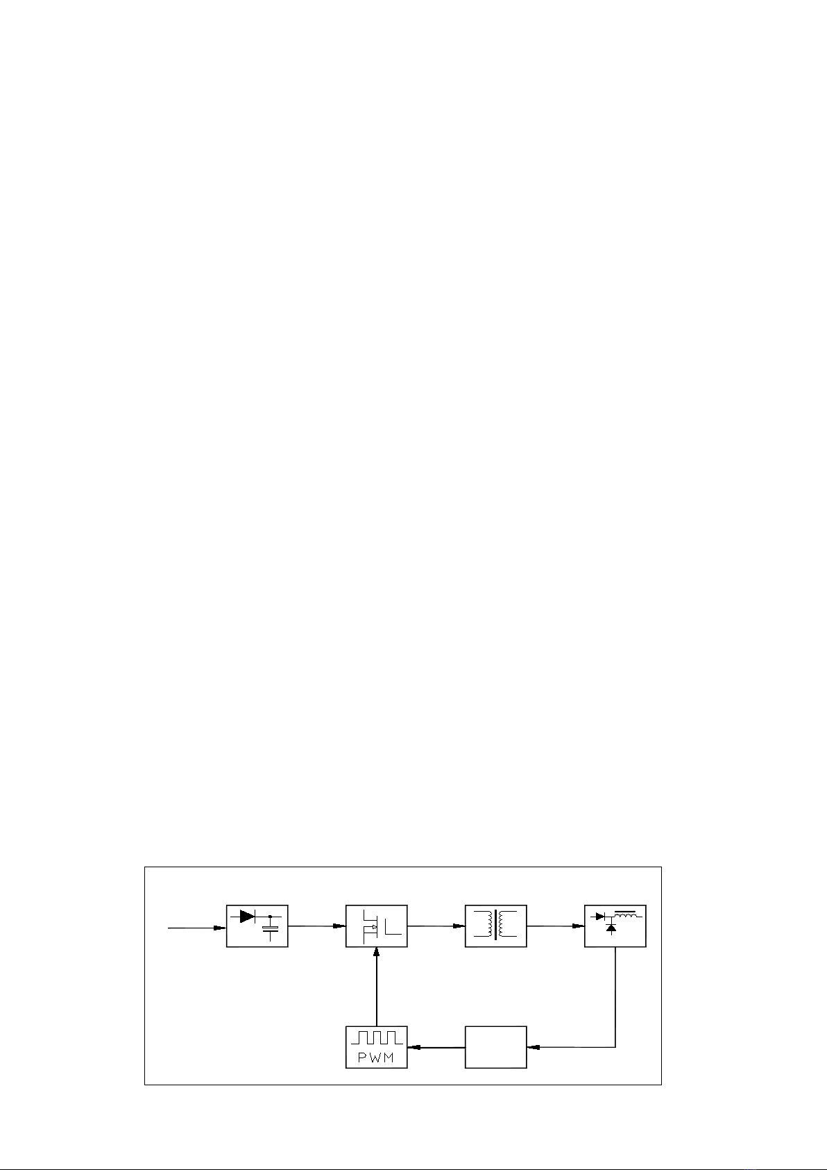
The inverter power supply firstly rectifies the 50 / 60Hz AC to DC, then converts the high-power
switching device (IGBT) into high-frequency voltage through pulse width modulation (PWM), and
then reduces the voltage to rectify, and then outputs the high-power DC power. The volume and
weight of welding machine are greatly reduced by taking inverter technology, and the efficiency
is increased by more than 35%. The features of this series of welding machines are: high
efficiency, energy saving, light weight, no electromagnetic noise, good dynamic characteristics,
stable arc and easy control of molten pool. It has high no-load voltage and good ability
compensation, which is widely used. It can weld stainless steel, alloy steel, carbon steel, copper
and other non-ferrous metals. The machine has four functions: MIG, TIG, CUT, MMA, very flexible
and convenient for all welding workers.
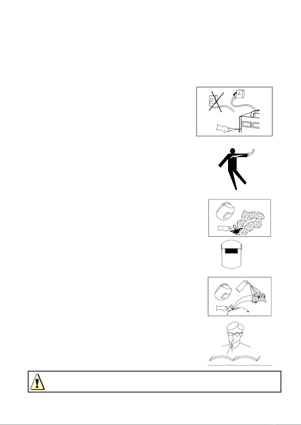
The machine is mainly used in industry. It will produce radio wave, so the worker should make
fully preparation for protection.
Block Diagram
I N P U T
C O N T R O L

3
2. SAFETY WARNING
Welding and cutting is dangerous to the operator, people in or near the working area, and the
surrounding, if the machine is not correctly operated. Therefore, the performance of
welding/cutting must only be under the strict and comprehensive observance of all relevant
safety regulations. Please read and understand this instruction manual carefully before the
installation and operation.
WARNING !
Electric leakage protecting switch should be added when using the machine!!!
The switching of function modes is possibly
damaging to the machine, while the welding
operation is performed.
Do disconnect the electrode-holder cable with the
machine, before the performance of welding.
A safety switch is necessary to prevent the machine
from electric leakage.
Welding tools should be of high quality.
Operators should be qualified.
ELECTRIC SHOCK: IT COULD BE FATAL!
Connect the earth cable according to standard
regulation.
Avoid all contact with live electrical parts of the
welding circuit, electrodes and wires with bare
hands. It is necessary for the operator to wear dry
welding gloves while he performs the welding task.
The operator should keep the working piece
insulating from himself/herself.
SMOKE AND GAS GENERATED WHILE WELDING OR
CUTTING: HARMFUL TO PEOPLE’S HEALTH.
Avoid breathing the smoke and gas generated while
welding or cutting.
Keep the working area well ventilated.
FIRE HAZARD
The welding splash may cause fire, thus remove
flammable material away from the working place.
Have a fire extinguisher nearby and have a trained
person ready to use it.
Noise: possibly harmful to peoples’ hearing.
Noise is generated while welding/cutting, wear
approved ear protection if noise level is high.
Machine fault:
Consult this instruction manual.
Contact your local dealer or supplier for further
advice.

4
3. TECHNICAL PARAMETERS TABLE
Model
Parameters
M CT-520DPL PRO
Mode
CUT
TIG
MMA
MIG
Input voltage(V)
AC220±15%
Frequency (Hz)
50/60
Rate input current(A)
40
26
40
34
Current Range(A)
20-50
10-200
10-200
50-200
No-load voltage(V)
310
64
64
64
Rate output voltage(V)
100
18
28
24
Remote control
/
/
/
/
Ignition way
HF
HF
TOUCH
TOUCH
Efficiency(%)
77
77
77
77
Duty Cycle(%)
30
30
30
30
Power factor
0.73
0.73
0.73
0.73
Insulation Class
H
H
H
H
Housing Protection
Class
IP21S
IP21S
IP21S
IP21S
Weight(kg)
14.3
Dimensions(mm)
490X215X325

5
12
8
7
7
11
4. Structure of welder
1. Control panel
Refer panel schematic for
details
2. MIG Torch ‘Euro Style’
Connection Socket
3. TIG/CUT Torch Connection
Socket
4. Polarconversion line
5. Aero socket -For spool gun
function
6. Positive (+) Welding Output
Terminal
7. Negative (-) Welding Output
Terminal
8. MIG gas
9. TIG/CUT gas
10. Power source switch
11. Power source input
12. reducing valve
1
2
3
4
5
6
7
Figure 2
8
9
10
Figure 1
12

6
M CT-520DPL PRO panel description:
1
Wire Check Button
2
Welding model selection:MIG 2T/MIG 4T, Plasma CUT, HF TIG, SPOT, MMA
3
MIG Synergic/MIG Manual/TIG PULSE Selection: Press to select MIG Synergic mode (wire
diameter) or MIG Manual mode or DC Pulse TIG
4
TIG Parameter Selection Button: Press to select different TIG parameters (move right)
5
Parameter Adjust Knob: Adjust to increase or decrease various parameters
6
TIG Parameter Selection Button: Press to select different TIG parameters (move left)
7
Function Selection Button: Press to select CO2 / mixed gas / gasless in MIG mode, or VRD
in MMA mode, or 2T/4T trigger in TIG mode
8
Function Selection Button: Press to select Hot-start / Hot-start time / Arc-force in MMA
mode, or Inductance in MIG mode, or 2T/4T trigger in CUT mode
9
Job Storage Button: Press to call the saved job (total 10 groups of jobs). Parameters of one
job will be saved after 5 seconds without adjustment
10
Digital Display for Job Number
11
Digital Display for Current, Wire Feeding Speed, Hertz
12
Digital Display for Voltage, Pulse Width, Pulse Time
13
Gas Check Button

7
5. INSTALLATION INSTRUCTION
The machine is equipped with power voltage compensation device. When the power voltage
fluctuates between±15% of rated voltage, it still can work normally.
When the machine is used with long cables, in order to prevent voltage form going down, bigger
section cable is suggested. If the cable is too long, it may have great affluence on the arc-striking
or other performance of cutting system, e.g. the HF arc-striking performance get weak or the
system work abnormally. So cables of configured length are suggested.
5.1 Make sure intake of the machine is not blocked or covered to avoid malfunction of cooling
system.
5.2 Connect the protective gas source. The gas supply passage shall include a gas cylinder, an
argon gas pressure reducing flowmeter and a gas pipe. The connecting portion of the gas pipe
shall be fastened with a hose clamp or other articles to prevent argon gas leakage and air ingress.
5.3 Ground the cables with section area no less than 6mm2to the housing, the way is connecting
screw in the back of the power source to ground device, or make sure ground terminal of power
socket is firmly connected. Both ways can be used for absolute safety.
5.4 According to the input voltage level of the welding machine, connect the power line to the
distribution box of the corresponding voltage level. Do not connect the wrong voltage. Also
ensure that the error of the power supply voltage is within the allowable range.

8
5.5 Welding Set Up & Operation
NOTE:
Please connect the power line of the welder to the input voltage consistent with the parameters
on the machine nameplate.
5.5.1Welding wire reel installation
Warning! -Before changing the feed roller or wire spool, ensure that the
mains power is switched off
Warning! -The use of excessive feed tension will cause rapid and
premature wear of the drive roller, the support bearing and the drive motor.
Loose the wire spool retaining
knob,install the wire reel on the holder
of wire feeding machine, the hole of
wire reel should align with fixed pin on
the holder.
Loose tensioner arm,choose different
wire feeding groove according to the
wire dimension. (Note: aluminum
welding chooses U-shape groove, other
welding wire choose the V-shape
groove)
Loose the nut of wire pressing roller,
thread the welding wire from the spool
through the wire input guide tube,
through the roller groove and into the
outlet guide tube. Note: adjust the
tensioner and impact the wire, to make
sure the wire will not slide. Avoid the
wire deformation due to the oversize
pressure.
Release the wire by rotating the wire
reel anticlockwise. In order to avoid
wire loose, the new wire reel will fix the
top of wire on the edge of wire reel.
Please cut off this top of wire.
choose different wire feeding groove
position according to the wire diameter.
Press the "Wire Check" button on the
panel, let the wire out of the nozzle.

9
5.5.2MIG Welding Installation
By pressing function selection button on front panel ,To select 2T or 4T working mode.
By pressing setting button (3)to select wire diameter;By pressing setting button (7)to select gas
type;By pressing setting button (7)to select Aluminum welding,ALSI/ALM.Note,When having aluminum
welding, MIG torch should change to use the graphite guide wire tube,and wire feeder should change
to use U-shaped roller.
By pressing setting button (8)to adjust inductance.
By pressing “Gas Check” button to check gas.
After finish the installation and setting, press the MIG torch switch to start welding working
By rotating the knob to adjust welding voltage.The larger the Welding voltage, the longer the arc,
the shallower the melting depth and the wider the melting width.
By pressing the encoder to switch and adjust the wire feeding speed. The larger the current is,
the faster the wire feeding speed will be. In this case, the gas flow can be adjusted appropriately.
Note: For details,please refer to Page6, the “Panel description”.
220V
gas cylinder
Connect the MIG Torch Euro Connector to the torch
socket on the front of the welder . Secure by firmly
hand tightening the threaded collar on the MIG
Torch Euro Connector clockwise.
Check that the correct gas shielded wire, matching
drive roller and welding tip are fitted.
Connect Polar conversion line to the positive (+)
welding output terminal .
Connect Earth Lead Quick Connector to the
negative (-) output welding terminal .
Connect Earth Clamp to the work piece. Contact
with work-piece must be strong contact with clean,
bare metal, with no corrosion, paint or scale at the
contact point.
Connect gas cylinder to the MIG gas inlet.Turn on
the gas valve and adjust to the desired flow.
Connect to AC 220V input voltage,Turn on the
power switch to start the machine.

10
5.5.3 TIG Welding Installation
By pressing function selection button on front panel ,to select TIG working mode.
By pressing setting button (3)to turn ON or OFF pulse;By pressing setting button (8)to select
2T or 4T working mode.
Under Pulse node, by pressing button to select and adjust the welding parameter.
By pressing “Gas Check” button to check gas.
When select “Cold”function, by pressing button to select and adjust the welding
parameter.
Note:Cold welding suitable for thin plate welding.
Note: For details,please refer to Page6, the “Panel description”.
Connect Lift TIG torch Quick Connector to
the negative (-) output welding terminal.
Connect Earth Lead Quick Connectorto
the positive (+) welding output terminal.
Connect the air hose of Lift tig torch with
the Argon meter connector. See picture
below.
Connect gas cylinder to the TIG gas
inlet.Turn on the gas valve and adjust to
the desired flow. Connect to AC 220V
input voltage,Turn on the power switch to
start the machine.
220V
gas cylinder

11
5.5.4 Cutting Installation
By pressing function selection button on front panel ,to select CUT working mode.
By pressing “Gas Check” button to check gas.If the gas is normal, press the cutting torch
switch to start cutting work.
By pressing setting button (6)to adjust Post-Flow time.
By rotating the knob to adjust cutting current.The cutting thickness increases with the increase of
current.
Note: For details,please refer to Page6, the “Panel description”.
Air Compressor
220V
Connect cutting torch to the machine
connector, tighten the nut and connect the
torch switch to the switch control socket,
tighten the nut.
Connect polar conversion line to the
negative (-)
Connect Earth Lead Quick Connector to
the
positive (+) output welding terminal. 。
After install reducing valve,connect Air
compressor to the CUT gas inlet. Connect
to AC 220V input voltage,Turn on the
power switch to start the machine.

12
5.5.5 MMA welding Installation
By pressing function selection button on front panel ,to select MMA working mode.
By rotating the knob to adjust welding current to start MMA welding.
By pressing setting button (7),select to turn ON or OFF VRD function.The VRD function is the
Voltage Reduce Device,when turn it on,No-load voltage will drop to 15V.By pressing setting button (8),
to select and adjust Hot Start current/Hot Start time and Arc force current,which make the arc to
start easier and with better welding result.
Note: For details,please refer to Page6, the “Panel description”.
WARNING!
It is strictly forbidden to insert or remove any cable or connector in use during the
welding process. This operation will endanger personal safety and cause serious
damage to the equipment.
220V
Connect Electrode holder Quick
Connector to the positive (+) welding
output terminal
Connect Earth Lead Quick Connector to
the negative (-) output welding terminal
See picture below.
Connect to AC 220V input voltage,Turn
on the power switch to start the
machine.

13
6. PRECAUTIONS
6.1 Surroundings
6.1.1 The welding operation should be carried out in a relatively dry environment, and the air
humidity should generally not exceed 90%.
6.1.2 The ambient temperature should be between -10C and 40C.
6.1.3 Avoid welding in daylight or rain, and do not allow water or rain to seep into the welder.
6.1.4 Avoid welding work in dusty areas or in corrosive atmospheres.Avoid gas-shielded welding
operations in environments with strong air flow.
6.2 Safety
6.2.1 Overvoltage, overcurrent and overheat protection circuits have been installed in our welding
machine. When the grid voltage, output current and internal temperature exceed the set standard,
the welder will automatically stop working; but excessive use (such as voltage over High) will still
cause damage to the welder, so you still need to pay attention to the following matters.
6.2.2 Ensure good ventilation.
Our welding machine is a small welding machine. When operating, there is a large working current,
and natural ventilation can not meet the cooling requirements of the welding machine. Therefore,
a fan is installed to effectively cool the welding machine to make it work smoothly.
The user should confirm that the ventilation is not covered or blocked, and the distance between
the welder and the surrounding objects should be no less than 0.3 meters. The user should
always pay attention to maintain good ventilation, which is better for the welder and guarantees a
longer service life. very important.
6.2.3 No current overload
The user should remember to observe the maximum allowable load current (relatively selectable
load continuation rate) and keep the welding current not exceeding the maximum allowable load
current.Current overload will significantly shorten the life of the welder and may even burn the
welder.
6.2.4 No too high voltage
The power supply voltage is listed in the “Main Performance Parameters” table. Under normal
circumstances, the voltage automatic compensation circuit in the welder will ensure that the
welding current is kept within the allowable range. If the power supply voltage exceeds the
allowable value, the welder will be damaged and the user should fully understand the situation
and take appropriate precautions.
6.2.5 A grounding screw is attached to the rear of each welder and marked with a grounding mark.
Before use, use a cable with a section larger than 6mm2 to reliably ground the welder's casing to
discharge static electricity or prevent accidents due to electric leakage.
6.2.6 If the welder exceeds the standard load continuation rate during operation, the welder may
suddenly enter the protection state and stop working. This means that the welder exceeds the
standard load continuation rate. Excessive heat energy triggers the temperature control switch,
causing the welder to stop working while being in front. The the digital display shows -E2. In this

14
case, you do not have to unplug the power supply so that the cooling fan can continue to work to
cool the welder. When the digital display shows -E2 goes out, the temperature drops to the
standard range and the welding can be restarted.
NOTICE: In the period of guarantee maintenance, if user makes wrong check and repair for
malfunction of welding machines without our permission, the free maintenance guarantee offered
will be invalid
7. TROUBLESHOOTING AND FAULT FINDING
Blind experiment and careless repair may lead to more problems and make formal check and
repair more difficult. When the machine is electrified, the bared parts contain life-threatening
voltage. Any direct and indirect touch will cause electric shock, and severe electric shock will
lead to death.Power must be turned off for all checking and maintenance, before opening the
housing, make sure the power plug is disconnected.
7.1 Remove dust by dry and clean compressed air regularly, if welding machine is operating in
environment where is polluted with smokes and pollution air, the machine need removing dust
everyday.
7.2 Pressure of compressed air must be inside the reasonable arrangement in order to prevent
damaging to small components of inter-machine.
7.3 Check inter circuit of welding machine regularly and make sure the cable circuit is connected
correctly and connectors are connected tightly (especially insert connector and components). If
scale and loose are found, please give a good polish to them, then connect them again tightly.
7.4 Avoid water and steam enter into inter-machine, if they enter into machine, please dry
inter-machine then check insulation of machine.
7.5 If welding machine will not be operated long time, it must be put into packing box and store in
dry environment.

15
Fault symptom
Remedy
The power indicator does not
light, the fan does not turn, no
welding output
1. The power switch is broken.
2. Confirm that the power grid connected to the input cable has power.
3. Check if the input cable has a break.
The power switch indicator is on,
the fan does not turn or rotates
for a few times to stop, no
welding output
1. It is possible to input the wrong connection on the 380V power
supply, causing the overvoltage protection circuit to start, and then
reconnect it to the AC110V\220V power supply and restart it.
2.AC110V\ 220V power is unstable (the input line is too long) or the
input line is connected to the power grid, causing the overvoltage
protection circuit to start, increasing the wire diameter of the grid
input line or fastening the input line node. This phenomenon is in
shutdown 2 - After 3 minutes, the new boot will return to normal.
3. Continuously open and close the power switch in a short time,
causing the overvoltage protection circuit to start. Wait for 2-3
minutes and then restart it.
4. The wires between the switch and the power board are loose and
retightened.
5. The main circuit 24V relay on the power supply board is not
connected or damaged, check the 24V power supply and relay.
The fan turns, the abnormal
indicator light is not bright, there
is no high-frequency discharge
"sa sa sa" sound, and the "arc
welding" can not start the arc.
1. The voltage of the positive and negative poles of the VH-07 plug-in
of the multimeter to the MOS board should be about DC308V.
2. The auxiliary power supply on the MOS board has a green indicator
light. If the light is not on, the auxiliary power supply is not working.
Look for the fault point or contact the dealer.
3. Check the poor connection of various patch cords in the machine.
4. Control circuit problems, find the cause or contact the dealer.
5. The control line on the welding torch is broken.
The abnormal indicator light is not
lit, there is a high-frequency
discharge "sa sa sa" sound, no
welding output.
1. The welding gun cable is broken.
2. The ground wire is broken or not connected to the welded
workpiece.
3. The positive output terminal or the welding torch gas output terminal
is loose from the connection inside the machine.
Abnormal indicator light does not
light, no high frequency discharge
"sa sa sa" sound, "LIFT TIG
welding" can start arc.
1. The primary line of the arcing transformer has poor contact with the
power board and is retightened.
2. The discharge nozzle is oxidized or the distance is remote. The
surface oxide film of the discharge nozzle is treated or the distance of
the discharge nozzle is adjusted to 1 mm.
3. The individual components of the high-frequency arc-ignition circuit
are damaged, and the replacement is found.

16
Abnormal indicator light is on, no
output
1. It may be overcurrent protection. Please turn off the machine. When
the abnormal indicator light is off and then restarted, it can be restored.
2. may be overheat protection, do not need to shut down for 2-3
minutes, the machine can naturally return to normal.
3. It may be that the inverter circuit is faulty. Please unplug the power
supply plug of the main transformer on the MOS board (near the fan
VH-07 plug-in) and restart it:
(1) If the abnormality indicator is still on, turn off the power plug of the
high-frequency pilot arc power supply (near the fan VH-03 plug-in) and
turn it back on:
a. If the abnormal indicator is still on, the individual FETs on the MOS
board are damaged.
b. If the abnormal indicator is not lit, the step-up transformer in the
high-frequency arc-rising circuit on the power supply board is broken
and replaced.
(2) If the abnormal indicator does not light:
a. It may be damaged in the middle plate transformer. The primary
inductance and Q value of the main transformer can be measured by
the bridge.
b. It may be that the transformer secondary rectifier is individually
broken down, and the same type of rectifier is found and replaced.
4. It may be that the feedback circuit is open.
Can not break the oxide film when
welding aluminum
1. The welding gear selection is incorrect;
2. The duty cycle adjustment is too small;
3. The secondary inverter has field tube damage.
Tungsten needle burnt seriously
The duty cycle is adjusted too much to reduce the duty cycle.

17
Fault symptom
Exclude
The fan does not rotate, the
digital meter has no display, and
there is no welding output.
1. Confirm that the air switch is intact or closed.
2. Confirm that the power grid connected to the output cable has
power.
3. The thermistor (four) on the power supply board is damaged (this is
usually caused by DC24V relay failure or poor contact contact).
4. The power board (base board) is faulty and there is no DC537V
voltage output.
5. The auxiliary power supply on the control panel has failed.
The fan turns, the abnormal
indicator light is not bright, there
is no high-frequency discharge
"sa sa sa" sound, and the "LIFT
TIG welding" can not start the arc.
1. Check all kinds of patch cords in the machine for poor contact.
2. Control circuit problems, find the cause or contact the dealer.
3. The control line on the welding torch is broken.
Abnormal indicator light is off,
there is high frequency discharge
"sa sa sa" sound, no welding
output
1. The welding gun cable is broken.
2. The ground wire is broken or not connected to the welded
workpiece.
3. The positive output terminal or the torch gas output terminal is loose
from the connection inside the machine.
Abnormal indicator light is not lit,
no high-frequency discharge "sa
sa sa" sound, arc welding can
start arc
1. The primary line of the arcing transformer is in poor contact with the
arcing plate and is retightened.
2. The discharge nozzle is oxidized or the distance is remote. The
surface of the discharge nozzle is treated with an oxide film or the
distance of the discharge nozzle is about 1 mm.
3. Hand soldering argon welding conversion switch is damaged and
replaced.
4. The individual components of the high-frequency arc-trigger circuit
are damaged, and the replacement is found.
Abnormal indicator light is on, no
output
1. It may be overcurrent protection. Please turn off the machine. When
the abnormal indicator light is off and then restarted, it can be restored.
2. may be overheat protection, do not need to shut down for 2-3
minutes, the machine can naturally return to normal.
3. It may be that the inverter circuit is faulty. Please unplug the power
supply plug of the main transformer on the MOS board (near the fan
VH-07 plug-in) and restart it:
(1) If the abnormality indicator is still on, turn off the power plug of
the high-frequency pilot arc power supply (near the fan VH-03 plug-in)
and turn it back on:
a. If the abnormal indicator is still on, the individual FETs on the MOS
board are damaged.
b. If the abnormal indicator is not lit, the step-up transformer in the
high-frequency arc-rising circuit on the power supply board is broken

18
and replaced.
(2) If the abnormal indicator does not light:
a. It may be damaged in the middle plate transformer. The primary
inductance and Q value of the main transformer can be measured by
the bridge.
b. It may be that the transformer secondary rectifier is individually
broken down, and the same type of rectifier is found and replaced.
4. It may be that the feedback circuit is open.
Tungsten needle burnt seriously
The duty cycle is adjusted too much to reduce the duty cycle.
Can not break the oxide film when
welding aluminum
1. The welding gear selection is incorrect;
2. The duty cycle adjustment is too small;
3. The secondary inverter has field tube damage.

19
8. EXPLOSIVE VIEW
NO.
name
Consumabl
es
NO.
name
Consumabl
es
1
Front plastic panel(down)
14
Double pressure plate
Yes
2
Front/ rear plastic panel(up)
15
Main board
Yes
3
Front metal panel
16
Fan
Yes
4
PCB Control panel
Yes
17
Rear Metal Panel
5
Panel cover
18
Plastic Rear Panel
Down
6
Metal Bottom Plate
19
relief valve support
7
Median Septum
20
Reducing valve
8
High frequency board
Yes
21
Handle
9
Control board
Yes
22
Machine Cover
10
Rectifier Bridge
Yes
23
Side panel
11
IGBT
Yes
24
Wire spool
12
Fast recovery Diode
Yes
25
Wire feeder
13
Rectifier board
Yes
26
Wire feeder support
This manual suits for next models
1
Table of contents
Other ANDELI Welding System manuals
Popular Welding System manuals by other brands

Ritmo
Ritmo FLOW HD-PRO operating instructions

Miller Electric
Miller Electric Digi-Meter RMS (AC-DC) owner's manual

BINZEL-ABICOR
BINZEL-ABICOR MIG B 15 operating instructions

ESAB
ESAB Origo Feed 302N P0 User manual and spare parts

Uni-Mig
Uni-Mig KUMJRRW165MIG operating manual

FRONIUS
FRONIUS LaserHybrid Series operating instructions

Elettro C.F.
Elettro C.F. Plasma Series instructions

Alfain
Alfain 5.0238-3 operating manual

FRONIUS
FRONIUS Profinet Robacta TX operating instructions

FRONIUS
FRONIUS TransPocket 150 Update Procedure

Rtech
Rtech PROArc 175 Operation instructions

JC MACHINERY & TOOLS
JC MACHINERY & TOOLS JC-4200-PM user manual