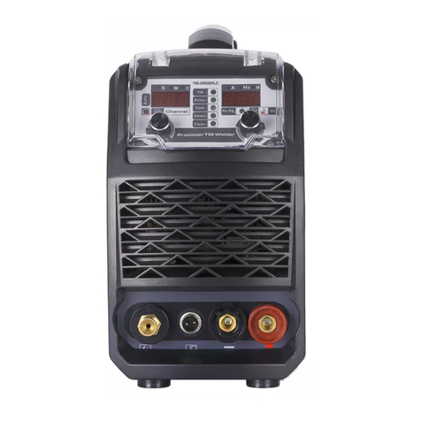
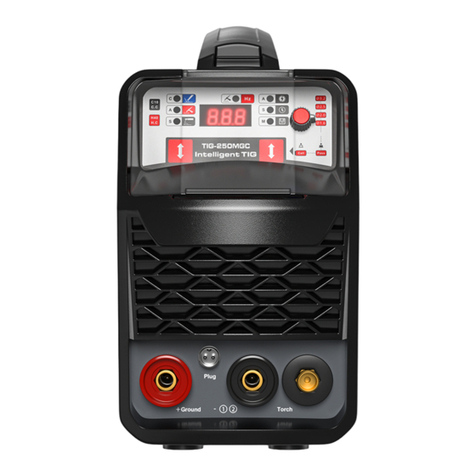
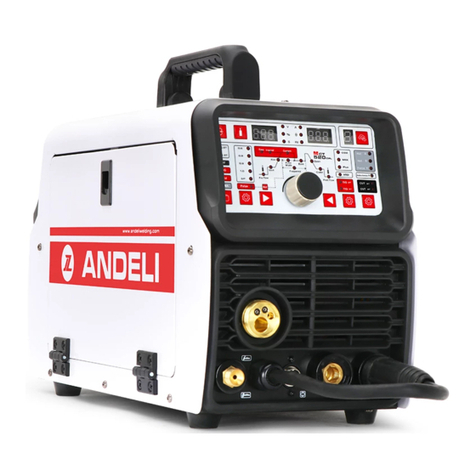
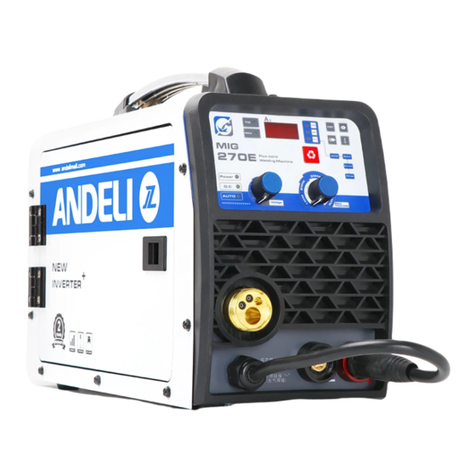
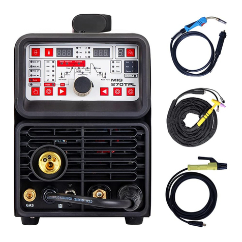
ANDELI TIG-250MGLC User manual

USER`S MANUAL
(Please read carefully before operation)

- 1 -
Please read first
Thank you for purchasing our welder products!
If you can correctly install and use the equipment, it will
be of great benefit to your safety and that of others. Please do
not install, use or repair the equipment without carefully
reading the instructions.
Date of purchase:
Welder No.:
Welding model number:
Place of purchase:

- 2 -
table of Contents
1. Use and characteristics:........................................................................... 3
2. Safety Precautions........................................................................................ 3
3. EMC Precautions.............................................................................................. 5
4. Key technical information.......................................................................... 7
5. Welding machine installation:................................................................ 8
6. Model compilation and description:...................................................... 9
7. Summary of principles:............................................................................ 10
8. Operation instructions:.......................................................................... 11
9. Points for Attention and Maintenance of Welding Machine:........ 20

- 3 -
Uses and characteristics
TIG cold welding machine series inverter DC gas shielded welding machine
set manual welding, common argon arc welding, cold welding, cleaning four
functions,it can realize the welding of carbon steel, stainless steel, copper,
titanium and other materials. Due to the ideal static and external
characteristics of this series of welders,property and good dynamic
characteristics, control function is relatively complete, so it shows the
following characteristics:
IGBT high frequency soft switching conversion, high efficiency, small
volume, light weight;
The advanced control scheme significantly improves the performance of
the welder and meets the welding process requirements to a greater
extent;
MMA welding, common TIG welding, cold welding, cleaning machine for
multiple purposes;
Cold welding is suitable for spot welding of thin plates, and the
workpiece does not change color;
Cleaning function, cleaning common argon arc welding workpiece color;
Easy arc starting, stable arc and high welding quality;
Hand arc welding has small spatter, stable current, high reliability
and good weld formation;
Digital panel adjustment, complete functions, multi-parameter
adjustment;
Safety Precautions
General safety precautions
Please be sure to observe the precautions stipulated in this manual,
otherwise accidents may occur.
For the design and construction of input power supply, the selection

- 4 -
of installation site, and the use of high-pressure gas, please follow
the relevant standards.
Unrelated personnel should not enter the welding site.
Please have qualified personnel to install, repair, maintain and use
the welding machine.
The welding machine must not be used for purposes other than welding
(such as charging, heating, pipe thawing , etc.).
If the ground is uneven, pay attention to prevent the welding machine
from tipping over.
Prevent electric shock or burns
Do not touch live parts.
Professional electricians are required to ground the welding machine
with copper wires of specified cross section.
Professional electricians are required to connect the welding machine
to the power supply with the copper wire of the specified cross section,
and the insulation sheath shall not be damaged.
When working in a humid place with limited activity, ensure the
insulation between the body and the base material.
When working at heights, use a safety net.
When not in use, please turn off the input power.
Avoid the harm of welding smoke and gas to human body
Please use the prescribed exhaust equipment to avoid accidents such
as gas poisoning and suffocation.
When working on the bottom of the container, protective gas will be
deposited around, causing suffocation. Special attention should be
paid to ventilation.
Avoid the harm of welding arc light, spatter and welding slag to
human body.

- 5 -
Please wear protective glasses with sufficient shading. Arc light can
cause eye irritation,spatter and welding slag can burn the eyes.
Please use leather protective gloves for welding, long-sleeved clothes,
hats, foot protectors, apron and other protective equipment to avoid
arcing, splash and welding slag burns and skin burns.
Prevent fire, explosion, rupture and other accidents
No combustible materials should be placed in the welding place.
Splashes and hot welding seams can cause fire.
The welding cable and the base material must be connected and fastened,
otherwise it will cause heat and cause a fire.
Please do not weld in flammable gas or on container containing
flammable substances, otherwise it may cause an explosion.
Do not weld the closed container, otherwise it will break.
Fire extinguishers should be prepared in case.
Prevents rotating moving parts from injuring people
Do not put your fingers, hair, clothes, etc. near rotating parts such
as cooling fans and wire feed wheels.
When feeding the welding wire, please do not put the end of the welding
torch close to the eyes, face and body to avoid the welding wire from
hurting people.
Prevent the gas cylinder from falling down and the gas regulator
from rupturing
Cylinders should be securely fixed, and dumping may cause personal
accidents.
Do not place the gas cylinder in high temperature or sunlight.
When opening the cylinder valve, keep your face away from the gas outlet
to avoid hurting people with high-pressure gas.
Please use the gas regulator supplied or recommended by our company,

- 6 -
and observe its usage regulations.
To prevent the welding machine from hurting people during sports
When using a forklift or crane to transport the welding machine,
personnel should not be under the welding machine and in front of the
movement to prevent the welding machine from falling and being injured.
When hoisting, the rope should be able to withstand suffficient tension
and not be broken. The angle of the rope at the hook should not exceed
30 °.
EMC precautions
1、Overview
Welding can cause electromagnetic interference.
By adopting appropriate installation methods and correct methods of
use, the interference emission of arc welding equipment can be minimized.
The products described in this manual are Class A equipment (applicable to
all occasions except residential areas powered by public low-voltage power
systems)
Warning: Class A equipment is not suitable for residential
buildings powered by public low-voltage power supply systems. Due to conducted
and radiated disturbances, it is difficult to guarantee electromagnetic
compatibility in these places.
2、Environmental assessment recommendations
Before installing arc welding equipment, users should evaluate
potential electromagnetic disturbance problems in the surrounding
environment. The considerations are as follows:
(1) Are there other power supply cables, control cables, signal and
telephone lines above and around the arc welding equipment;
(2) Whether there are broadcasting and TV transmitting and receiving
equipment;
(3) Whether there are computers and other control equipment;

- 7 -
(4) Whether there is high-security equipment, such as industrial
protective equipment;
(5) Consider the health of the surrounding staff, such as those without
hearing aids and those with pacemakers;;
(6) Is there any equipment for calibration or testing;
(7) Pay attention to the noise immunity of other surrounding equipment.
Users should ensure that other devices used around them are
compatible, which may require additional protective measures;
(8) Time for welding or other activities.
The scope of the environment considered depends on the building structure
and other possible activities, which may exceed the boundaries of the building
itself.
3、Ways to reduce emissions
(1) Public power supply system
Arc welding equipment should be connected to the public power supply
system in the manner recommended by the manufacturer. If interference occurs,
additional precautions should be taken, such as access to the filter in the
public power supply system. For the fixed installation of arc welding
equipment, the shielding of the power supply cable should be considered. Metal
pipes or other equivalent methods can be used for shielding. The shielding
must maintain electrical continuity. The shielding layer should also be
connected to the welding power supply shell to ensure good electrical contact
between the two.
(2) Maintenance of arc welding equipment
Arc welding equipment should be routinely maintained according to
the method recommended by the manufacturer. When the welding equipment is
in operation, all entrances, auxiliary doors and covers on the equipment
should be closed and properly tightened. Arc welding equipment should not
be modified in any form, unless there are corresponding changes and

- 8 -
adjustments in the instructions. In particular, the spark gap of the arc
starting and stabilizing device must be adjusted and maintained according
to the manufacturer's recommendations.
(3) Welding cable
Welding cables should be as short as possible and close to each other,
close to or close to the ground.
(4) Bonding of equal potentiometers
Be sure to pay attention to the overlapping of all metal objects in
the surrounding environment. The overlapping of metal objects and workpieces
will increase the risk of work. When the operator touches these metal objects
and electrodes at the same time, there may be electric shock. The operator
should be insulated from all these metal objects.
(5)Workpiece grounding
For reasons such as electricity safety or the position and size of
the workpiece, the workpiece may not be grounded, such as the hull or steel
frame of the building. The connection between the workpiece and the ground
sometimes reduces the emission, but this is not always the case, so it is
necessary to prevent the increased risk of electric shock to the user or damage
to other electrical equipment caused by the workpiece grounding. When
necessary, the workpiece should be directly connected to the ground, but in
some countries it is not allowed to be directly grounded, and it can only be
achieved by selecting an appropriate capacitor according to the regulations
of the country where it is located.
(6)shield
Selective shielding of surrounding equipment and other cables can
reduce electromagnetic interference. For special applications, consider
shielding the entire welding area.

- 9 -
Main technical information
1、The main technical parameters
MODEL
TIG-250MGLC
Function
TIG
MMA
Power Supply Voltage(V)
AC220V±15%
Frequency(Hz)
50/60
No-Load Voltage(V)
56
Rated Input Power(KW)
4.1
5.6
Rated Input Current(A)
18.5
25.3
Welding Current Range(A)
5-170
10-150
Duty cycle (% 40℃
10min)
40%
170A/16.8V
150A/26V
100%
108A/14.3V
95A/23.8V
Power Factor
0.7
Efficiency(%)
85
(For hidden parameters,please refer to the parameter table below )
Welder installation
1.Installation Environment
(1) The welding operation should be carried out in a relatively dry
environment. The relative humidity of the air should not exceed 90%
at 20 ° C and 50% at 40 ° C.
(2) The ambient temperature during welding should be between -10 ° C and
+ 40 ° C, and between -20 and + 55 ° C during storage and
transportation.
(3) Avoid use in direct sunlight or in the rain in the open air, and do
not allow rainwater to penetrate into the welding machine.

- 10 -
(4) Avoid gas shielded welding operations in environments with strong air
flow.
(5) The inclination of the welding power source should not exceed 100,
and the altitude should not exceed 1000m.
(6) Avoid working in the environment with large dust, acid and corrosive
gas.
(7) The welding machine is more than 20cm away from the wall, and the
distance between the welding machine is more than 10cm.
2.Supply voltage quality
(1) The waveform should be a standard sine wave, the effective value is
220V15%, and the frequency is 50Hz / 60Hz.
3. Power input
Model
TIG-250MGLC
Input power
AC220V±
15%,50/60Hz
Grid minimum capacity
10
Input
protection
fuse
63
breaker
63
Cable
Input
side
4mm2
Output
side
25mm2
Ground
wire
4mm2
In the above table, the squares of the input, output, and ground wires
increase correspondingly with the longer cable length.
Note: The capacities of fuses and circuit breakers in the above table

- 11 -
are for reference only.
4.Equipment installation
The input power of this series of welding machine is single-phase 220V
/ 50Hz alternating current. The user should have a corresponding power
distribution board or cabinet, and should be equipped with an automatic air
switch or an iron shell switch, and the ground connection should be reliable.
4.1 Use of MMA welding:
1Reliable access to welding cables;
2Close the power switch of the arc welding power supply;
3Connect the input cable to the switchboard and close it.
4.2 Common TIG welding and cold welding:
1The welding torch is reliably connected to the negative electrode of
the welding machine, and the workpiece clamping wire is reliably connected
to the positive electrode of the welding machine;
2Reliably connect the trachea and air source;
3Turn on the power switch of the welding machine;
4Connect the input cable to the switchboard and close it.
4.3 Cleaning use:
1The cleaning gun is connected to the negative electrode of the welding
machine, and the work clamp wire is reliably connected to the positive
electrode of the welding machine;
2Close the power switch of the welding machine;
3Connect the input cable to the switchboard and close it.

- 12 -
Model compilation and description
Model compilation and description of TIG series welding machine are shown
in Figure 1:
W S ——×××
(Figure 1) Model compilation and description of TIG series welding machine
Brief principle
The schematic diagram of TIG series welding machine is shown in Figure 2:
Inverter Transformer filtering
Control
circuit
(Figure 2)Welding machine schematic
This welding machine adopts IGBT high-frequency inverter technology,
power frequency 220V power input, directly rectified and sent to the inverter
composed of IGBT and other devices to become high-frequency AC, and the
high-frequency AC obtained after the inverter passes through the
high-frequency transformer After stepping down, the high-frequency rectifier
rectifies and filters and outputs a DC current suitable for welding. Through
this process, the dynamic response of the welding machine is improved, the
volume and weight of the transformer and reactor are reduced, and the
efficiency of the whole machine is improved.
The design of the control circuit enables the welding machine to always
Specification
MMA
TIG
Rectification

- 13 -
achieve good welding process performance when the external conditions change
(such as grid voltage fluctuations and output cable lengths are different).
It is easy to start the arc, the arc is stable, the welding seam is well formed,
and the welding current can be continuously adjusted.
The output characteristics of TIG series welding machine are shown in Figure
3:
(Figure 3a)MMA output characteristics(Figure 3b)TIG output characteristics
Static external characteristics of MMA welding and TIG welding: drop
characteristics.
Operating instructions
1.Features
1. Welder pannel
The panel of the welding machine is shown in figure (4), which is used
for the function selection, parameter setting and welding output interface
of the welding machine.
U=20+0.05I
10
U=10+0.04I
44
34
20

- 14 -
(图 4) TIG-250MGLC(two functions)panel diagram
1.1.1 TIG-250GC function selection and parameter setting
1First button: (First from left)
焊接功能选择按钮。
2Second button:(Second from left)
Parameter selection button.
3Parameter value adjustment knob:
Adjust the value of each parameter.
4Digital Tube:
Display the value of each parameter.

- 15 -
5Welding function instruction
MMA;
TIG;
Cold welding, suitable for spot welding of thin plates;
Cleaning, cleaning the color of the workpiece after ordinary TIG
welding;
6Parameter indication
Display the current value of hot welding and cleaning;
Display TIG welding current time 1-250ms;
C0-5 can store self-adjusting parameters for TIG welding,
and C6-9 built-in parameters;
Hot welding: C6-spot welding 0.8mm board; C7-spot welding 1.0mm board;
C8-spot welding 1.5mm board; C9-spot welding 3.0mm board.
1.1.2Protection code
1Display OC, welding machine overheat and overcurrent protection;
1.1.3 Welding output interface
From left to right:
1Positive output fast socket: connect the welding clamp wire during
manual welding; connect the work clamp wire during hot welding, cold welding
and cleaning;
2Welding torch switch: connect to argon arc welding torch and cleaning
gun switch;
3Negative output fast socket: connect the work piece clamp wire during
manual welding; connect the cleaning gun fast plug during cleaning;
4Negative output gas-electric connector: hot-gas welding and
cold-welding gas-electric connector for argon arc welding torch;

- 16 -
(The parameters of the same type cold welding machine are the
same as above, not listed)
2.Installation method:
Note: Please strictly follow the steps below for installation and commissioning!
The electrical connection operation must be performed after turning off the
power switch of the distribution box!
The protection grade of this equipment is IP21, and it should be avoided in rain!
1Connect the welding input power line to the corresponding voltage level a
nd ≥60A circuit breaker (connect the ≥4 square power line);
2The input power line should be in good contact with the corresponding power
terminal or switch to prevent oxidation;
3Use a multimeter to measure whether the input voltage is within the fluctuation
range;
4Connect the yellow-green wire on the power cord and the grounding screw on the
rear panel to ≥4 square wires and ground them well;
5If the welding machine is placed on an inclined plane, the welding machine
should be fixed and not allowed to slide down;
6Each welding machine is equipped with an insulated handle, which is lifted by
hand when moving the welding machine;
2.1 Hot welding (general TIG welding)
1Tightly connect the air pipe to the air inlet of the rear plate of
the welding machine; the gas supply path should include a gas bottle, an argon
decompression flow meter and a gas pipe, and the connection part of the gas
pipe should be tightly tightened with a hose clamp to prevent leakage and air
ingress.
2Insert the gas-electric integrated interface of the argon arc welding

- 17 -
torch and the welding torch switch into the corresponding positions on the
panel and tighten clockwise.
3Connect the work clamp wire to the positive quick socket (character
"+ ground").
4Set the distance between the tungsten electrode of the argon arc
welding torch and the workpiece 2-4mm, press the welding torch switch to ignite
the arc, the current is the set value, and you can work at this time.
Titanium and its alloys——Parameter selection of tungsten argon arc welding
(for reference only)
Thick
ness
(mm)
Bevel
form
Number
of
weldin
g
layers
Tungsten
diameter
(mm)
Welding
wire
diameter
(mm)
Welding
current
(A)
Argon flow(L/min)
Nozzle
aperture
(mm)
0.5
1.0
1.5
2.0
2.5
I-sha
ped
groov
e
1
1
1
1
1
1.5
2.0
2.0
2.0-3.
0
2.0-3.
0
1.0
1.0-2.
0
1.0-2.
0
1.0-2.
0
2.0
30-50
40-60
60-80
80-110
110-120
8-10
8-10
10-12
12-14
12-14
6-8
6-8
8-10
10-12
10-12
14-16
14-16
14-16
16-20
16-20
10
10
10-12
12-14
12-14
3.0
4.0
5.0
6.0
7.0
8.0
Y-sha
ped
groov
e
1-2
2
2-3
2-3
2-3
3-4
3.0
3.0-4.
0
4.0
4.0
4.0
2.0-3.
0
2.0-3.
0
3.0
3.0-4.
120-140
130-150
130-150
140-180
140-180
140-180
12-14
14-16
14-16
14-16
14-16
14-16
10-12
12-14
12-14
12-14
12-14
12-14
16-20
20-25
20-25
25-28
25-28
25-28
14-18
18-20
18-20
18-20
20-22
20-22

- 18 -
4.0
0
3.0-4.
0
3.0-4.
0
10
20
22
25
30
Doubl
e
Y-sha
ped
groov
e
4-6
12
12
15-16
17-18
4.0
4.0
4.0
4.0
4.0
3.0-4.
0
4.0
4.0-5.
0
3.0-4.
0
3.0-4.
0
160-200
200-240
230-250
200-220
200-220
14-16
12-14
15-18
16-18
16-18
12-14
10-12
18-20
20-26
20-26
25-28
20
18-20
26-30
26-30
20-22
18
20
22
22
Stainless steel sheet-parameter selection of tungsten argon arc welding (for
reference only)
Thickness
(mm)
Connector
form
Tungsten
diameter
(mm)
Welding
wire
diameter
(mm)
Current type
Welding
current
(A)
Argon
flow
(L/min
)
Welding
speed
(cm/min)
1.0
1.2
1.5
Docking
Docking
Docking
2
2
2
1.6
1.6
1.6
DC positive
DC positive
DC positive
7-28
15
5-19
3-4
3-4
3-4
12-47
25
8-32
Aluminum and its alloys——Parameter selection of argon tungsten arc welding
(for reference only)
Thickness
(mm)
Beve
l
form
Number of
welding
layers
Tungsten
diameter
(mm)
Wire
diamete
r(mm)
pre-heat
temperat
ure(℃)
Welding
current(A)
Argon flow
(L/min)
Nozzle
aperture
(mm)
1.5
I-s
1/0
2
1.6-2
-
50-80
7-9
8

- 19 -
2
hap
ed
gro
ove
1/0
2-3
2-2.5
-
50-80
8-12
8-12
3
4
5
8
10
12
16
20
Y-s
hap
ed
gro
ove
1/0
1-2/1
1-2/1
2/1
3-4/1-2
3-4/1-2
4-5/1-2
4-5/1-2
3
4
4
5
5
5-6
6
6
2-3
3
3-4
4-5
4-5
4-5
5-6
5-6
-
-
-
100
100-15
0
150-20
0
200-22
0
200-26
0
150-180
180-200
180-240
260-320
280-340
300-360
340-380
360-400
8-12
10-15
10-15
16-20
16-20
18-22
20-24
25-30
8
8-12
8-12
10-12
14-16
14-16
16-20
20-22
16-20
22-25
Dou
ble
Y-s
hap
ed
gro
ove
2-3/2-3
2-3/2-3
6
6-7
5-6
5-6
200-26
0
200-26
0
300-380
360-400
25-30
30-35
16-20
20-22
2.3 Cleaning
1Connect the quick plug of the cleaning gun to the negative quick socket,
insert the welding gun switch, and tighten it clockwise;
2Connect the work clamp wire to the positive quick socket (character
"+ ground");
Table of contents
Other ANDELI Welding System manuals