Anden A100 User manual

DEHUMIDIFIER CONTROL
ON/OFF BUTTON
USED TO TURN
DEHUMIDIFIER ON
AND OFF
UP/DOWN
BUTTONS USED TO
CHANGE HUMIDITY
SETTING
MODE BUTTON
USED FOR OPTIONAL
VENTILATION FEATURE
INLET FILTER
ACCESS DOOR
DRAIN POWER
SWITCH
OUTLET
90-1853
READ AND SAVE THESE INSTRUCTIONS
Model A100 Dehumidifier
Installation and Operating Instructions
TABLE OF CONTENTS
SAFETY INSTRUCTIONS ..........................................2
SPECIFICATIONS .................................................3
SET UP DEHUMIDIFIER FOR INSTALLATION ........................4
Packaging Content .............................................4
Duct Collars....................................................4
Control Location................................................5
LOCATION CONSIDERATIONS .....................................5
DRAIN INSTALLATION ............................................6
Leveling .......................................................7
Condensate Pan, Condensate Pump and Float Switch ..............7
MODEL A77 – REMOTE CONTROL AND WIRING ....................8
Alternate External Controls ......................................8
SYSTEM SET UP & CHECKOUT .....................................9
Installer Test Mode.............................................10
START UP AND SEQUENCE OF OPERATION ........................11
Using the Dehumidifier Control ..................................11
Using Model A77 Remote Control ................................11
MAINTENANCE...................................................11
Clean or Replace the Filter ......................................11
Drain and Drain Insert Inspection................................ 12
Removing and Reinstalling the Drain Insert ...................... 12
TROUBLESHOOTING ............................................ 13
Table 2 – Diagnostic Codes ..................................... 13
Table 3 – Troubleshooting Guide . . . . . . . . . . . . . . . . . . . . . . . . . . . . . . . . 14
SERVICE PARTS ................................................. 15
LIMITED WARRANTY ............................................16

SAFETY INSTRUCTIONS
WARNING
1. 120 Volts may cause serious injury from electric shock. Disconnect electrical power before starting installation or servicing. Leave power
disconnected until installation/service is completed.
2. Sharp edges may cause serious injury from cuts. Use care when cutting plenum openings and handling duct work.
3. Dropping may cause personal injury or equipment damage. Handle with care and follow installation instructions.
CAUTION
1. Read all instructions before beginning installation.
2. Improper installation may cause property damage or injury. Installation, service, and maintenance must be performed by a qualified service
technician.
3. Do not use in pool applications. Pool chemicals can damage the dehumidifier.
4. Do not use solvents or cleaners on or near the circuit board. Chemicals can damage circuit board components.
5. Wait 24 hours before running the unit if it was not shipped or stored in the upright position
6. Do not use dehumidification to prevent window condensation in the winter. To address window condensation, use ventilation to lower
indoor humidity in the winter.
7. This appliance is not intended for use by persons (including children) with reduced physical, sensory or mental capabilities, or lack of
experience and knowledge, unless they have been given supervision or instruction concerning use of the appliance by a person responsible
for their safety.
8. Children should be supervised to ensure that they do not play with the appliance.
9. If the supply cord is damaged, it must be replaced by a special cord or assembly available from the manufacturer or its service agent.
2

SPECIFICATIONS
TABLE 1 – SPECIFICATIONS Model A100
Unit Weight 64 lbs
Shipping Weight 82 lbs
Capacity (AHAM DH-1-2008 80°F, 60% RH) 100 pints per day @ 280 CFM
Efficiency 2.6 L/kW-hr (5.7 pints/kW-hr) @ 80°F, 60% RH
Power (115 VAC, Single Phase, 60Hz) 6.9 Amps operating current
Dehumidifier Inlet Air Conditions Dehumidification: 50°F – 104°F, 40°F dew point minimum
Ventilation: 40°F – 140°F, 0% RH – 99% RH (non-condensing)
Filter MERV 11
Airflow External Static Pressure ("w.c.) Airflow (CFM)
0.0 280
0.2 245
0.4 210
0.6* 175
*Maximum design external static pressure.
3

SET UP DEHUMIDIFIER FOR INSTALLATION
IMPORTANT: Cut the strap securing the compressor shipping support
bracket and remove the strap and shipping bracket. See FIGURE 1.
PACKAGING CONTENT
1. Dehumidifier
2. 10" Inlet/Outlet Collars
3. Installation and Operating Instructions
4. Parts Bag
a. #10 x 1/2 Screws (9)
b. Threaded Barbed Fitting for Drain Connections
c. Torx Bit
5. 10 Foot, 3/4" Drain Tube
DUCT COLLARS
If suspending the unit over the canopy but not ducting the unit, no
duct collars are needed (see FIGURE 2). If ductwork will be installed to
a suspended unit, attach the inlet and outlet duct collars as shown in
FIGURE 3; the outlet cover does not need to be moved. If placing the
unit on the floor, remove the outlet cover and install the outlet collar to
the top of the unit, and relocate the cover to the end of the unit (see
FIGURE 4).
CLIP OFF
PLASTIC STRAP
REMOVE SHIPPING BRACKET
OUTLET COVER
OUTLET COVER OUTLET DUCT
COLLAR WITH
BACK DRAFT
DAMPER
INLET
DUCT
COLLAR
MOVE OUTLET
COVER AND
INSTALL OUTLET
DUCT COLLAR TO
TOP DISCHARGE
LOCATION
90-1908
90-1911
90-1909 90-1909
FIGURE 1 – REMOVE SHIPPING BRACKET
FIGURE 2 – HANGING INSTALL – NO DUCTING
FIGURE 3 – HANGING INSTALL WITH DUCTING FIGURE 4 – FLOOR MOUNT INSTALL
4

CONTROL LOCATION
The on-board control can be located on the top of the
dehumidifier or can be relocated to the front of the
dehumidifier if the control cannot be seen/accessed in
the top orientation. It may also be rotated 180 degrees
in either orientation as shown in FIGURE 6.
To move the control:
1. Remove the front control panel cover.
2. Remove the filter access door and filter.
3. Detach the on-board control by removing the four
(4) screws around the control. NOTE: Use one hand
to support the bottom of the on-board control
when removing.
4. Keep the control in the unit and relocate to the front
access hole.
5. Secure the control with the same four screws used
to attach the control to the top of the unit.
6. Secure the control panel cover to the top of the unit.
CONTROL
PANEL COVER
CONTROL
CONTROL
CONTROL
PANEL COVER
FILTER ACCESS DOOR
90-1884
FIGURE 5 – CONTROL LOCATION
90-2525
FIGURE 6 – CONTROL ROTATED 180 DEGREES
LOCATION CONSIDERATIONS
• Allow sufficient clearance for filter removal and to
prevent airflow obstruction
• Electrical service access will require the removal
of the side panel shown. Allow sufficient space for
service on this side of the unit.
• When suspending the unit, a condensate pan
with float switch is recommended to prevent any
leaks that may occur due to unforeseen drain line
obstructions.
TOP VIEW
FILTER MINIMUM
CLEARANCE FOR FILTER
(BOTH SIDES)
15"
6" MINIMUM CLEARANCE
FOR PROPER AIR FLOW
ELECTRICAL SERVICE
ACCESS THIS SIDE
6 FT. POWER CORD
90-1840
FIGURE 6 – FILTER ACCESS CLEARANCE
5

DRAIN INSTALLATION
The drain outlet on the dehumidifier can be hard piped using a 3/4" PVC Slip x 3/4" MNPT fitting and 3/4" nominal drain tubing or the provided 3/4"
MNPT x 3/4" hose barb fitting. 3/4" clear PVC tubing can be used to drain the dehumidifier. Always maintain a constant downward slope from the
dehumidifier to the drain and do not allow soft tubing to curl up which may result in air lock.
NOTE: PTFE thread seal tape is recommended for the threaded connection and hand tighten only. If hard pipe is used, PVC primer and cement is
recommended for the slip fit connection. Remove drain insert before priming and gluing in the PVC fitting. Replace drain insert after PVC glue has
fully dried.
CAUTION
Do not damage drain insert. The drain insert is a critical feature of the dehumidifier drain management system.
WARNING
Running the dehumidifier without the drain insert can lead to condensate leaks. See FIGURE 7.
DRAIN INSERT
90-2607
FIGURE 7 – DRAIN INSERT
6

LEVELING
The feet can be adjusted to level the unit and
accommodate drain fittings and secondary condensate
pans as required. Refer to top mounted bubble level
and adjust feet until bubble is within the outer circle.
Leveling is required to ensure proper drainage from
the dehumidifier. See FIGURE 8.
0.38" MIN
2.00" MAX
3/4" DRAIN
BUBBLE LEVEL
90-2592
FIGURE 8 – LEVEL THE UNIT
CONDENSATE PAN, CONDENSATE PUMP AND FLOAT SWITCH
A condensate pan is recommended when suspending
the dehumidifier over the canopy. Adhere to local
codes regarding draining of the condensate pan. If a
condensate pump is needed, install it in the condensate
pan as well.
Install a condensate overflow safety switch (i.e. float
switch) in the condensate pan, remove the factory
installed jumper wire between the Float Switch
terminals on the control and wire the float switch to the
dehumidifier as shown in FIGURE 9. Overflow safety
switches on condensate pumps can be wired to the
Float Switch terminals in a similar fashion.
FLOAT
Switch
DH DH
NORMALLY CLOSED
FLOAT SWITCH
90-1857
FIGURE 9 – FLOAT SWITCH WIRING
7

MODEL A77 – REMOTE CONTROL AND WIRING
NOTE: Use 18-22 AWG wire for control wiring.
Humidity can be controlled using the internal dehumidifier control, a
Model A77 control or a different external control like a thermostat.
Installing an external control eliminates the need to run the dehumidifier
blower for sampling as the control is constantly measuring the humidity
close to the canopy. When the humidity level rises above the setting,
the dehumidifier is turned on.
To install and use the Model A77 control, complete ALL steps:
1. Unplug the dehumidifier or turn off power to the circuit at the
breaker or fuse.
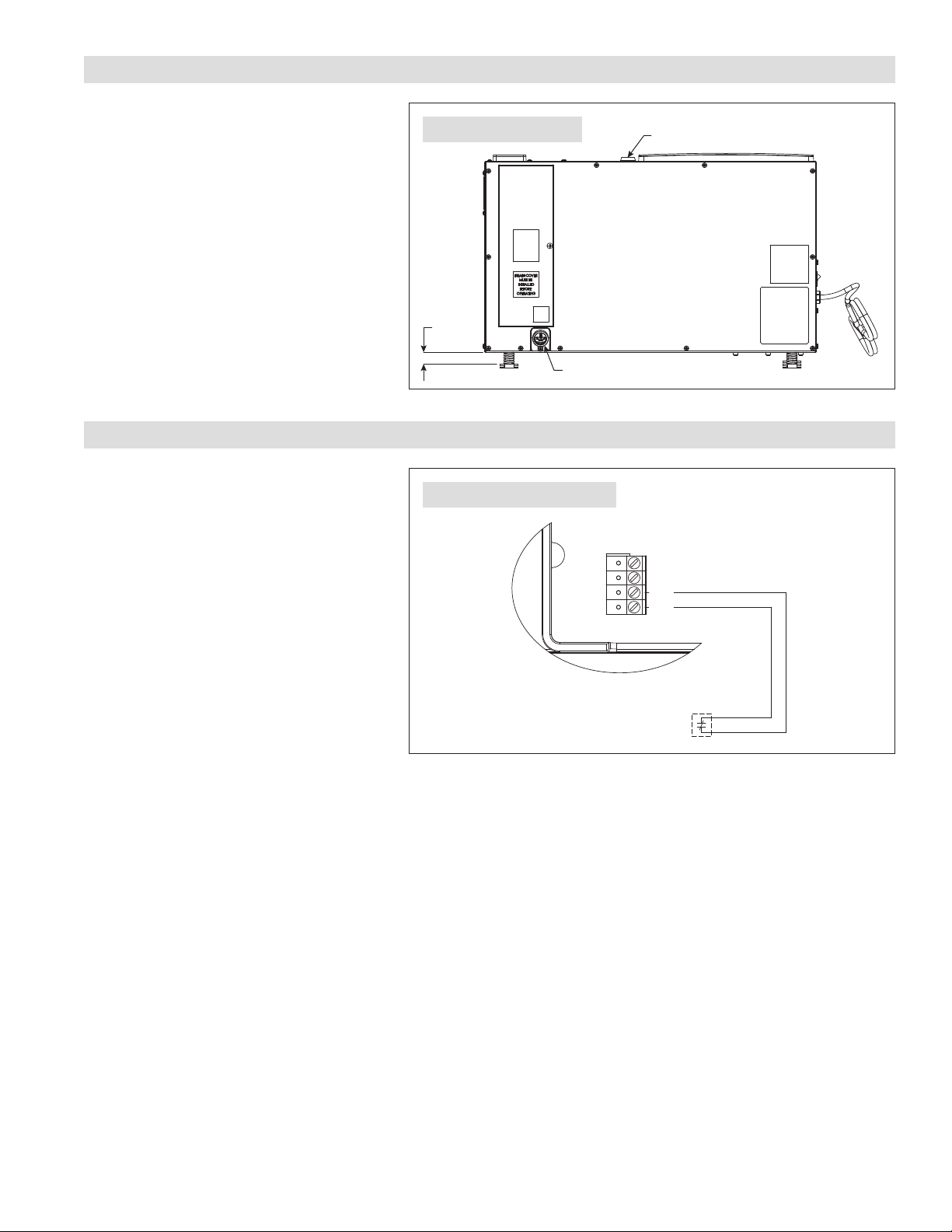
2. Run a 4-wire thermostat cable (use 18–22 AWG wire) from the
Model A77 to the control of the dehumidifier.
3. Trim about 1/4" of insulation from the end of the wires on each
end. Insert the wire into the terminals as shown in FIGURE 10 and
tighten to secure.
4. Restore dehumidifier power. There is a delay of three minutes after
restoring power before the dehumidifier will respond to the control.
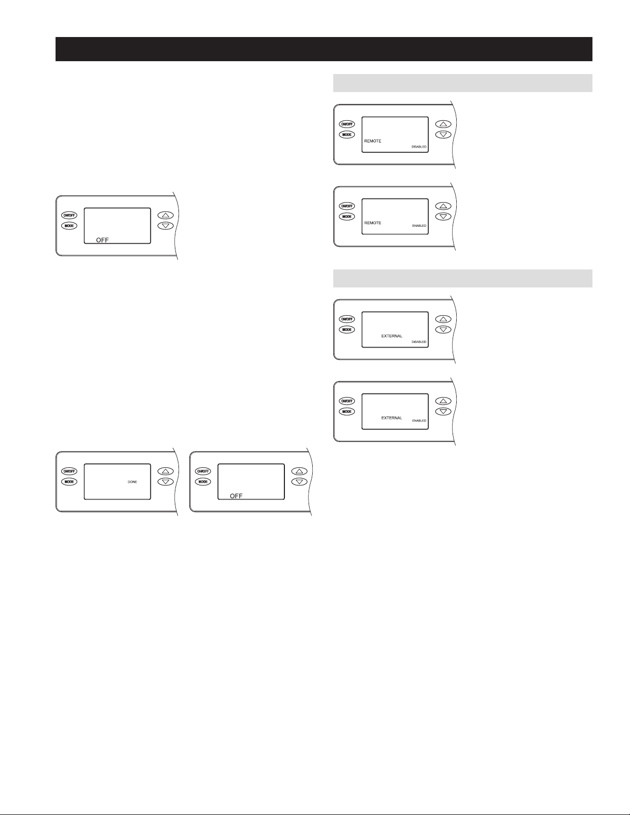
5. Set up the dehumidifier to ENABLE REMOTE control as shown on page 9.
6. See USING THE MODEL A77 OR EXTERNAL CONTROL on page 9 for start up instructions.
The Model A77 will measure the relative humidity and turn the dehumidifier on and off to control the humidity level to the desired setting. The
humidity setting can be adjusted from the control while the display allows easy access and monitoring of the humidity level in the space. It is
recommended that the Model A77 be mounted at/near canopy height. Shield the Model A77 from direct exposure to HPS or LPS lighting.
Press the ON button on the Model A77 to turn on the control. The UP/DOWN arrow buttons are used to set the desired humidity setting. At all other
times, the Model A77 will display the measured humidity level. Reference the Model A77 Installation and Operating Instructions for set-up.
ALTERNATE EXTERNAL CONTROLS
Alternatively, use any other humidity control system as long as it
has a dry contact, normally open output dedicated to controlling the
dehumidifier.
When using an external control, set up the dehumidifier to ENABLE
EXTERNAL control as shown on page 9. Reference the installation
literature provided with the alternative control for wiring, set-up and
operating details.
+ - A B ODT
SensorRemote
Gh Rf Cf Gs YW
HVAC EQUIP.
DH
DH
R/+
C/-
B
A
MODEL A77 CONTROL
FLOAT DH DH
SWITCH
EXTERNAL
CONTROL
90-1860
90-2542
FIGURE 10 – MODEL A77 REMOTE CONTROL WIRING
FIGURE 11 – ALTERNATE EXTERNAL CONTROL WIRING
8

SYSTEM SET-UP & CHECKOUT
Skip set up and proceed to INSTALLER TEST MODE on page 10 unless:
• A Model A77 or other external control is to be installed
• changing the air sampling rate
1. Make sure the wire access cover has been snapped back onto the
on-board control.
2. Plug unit in and turn power switch to ON.
3. The on-board control screen should display OFF.
90-1854
NOTE: If the display backlight is not on, the first button press (any
button) will only turn on the backlight. Press the button a second time
to achieve function.
4. Hold the MODE button on the on-board control for 3 seconds to
enter the Installer Set-up Menu.
5. Navigate through the following screens to set up the dehumidifier
for the installed application.
Use the UP or DOWN buttons to select items and use MODE to
switch to the next set-up option. To exit installer set-up, all options
must be scrolled through using the MODE button.
6. After the installer set up options have been completed, DONE will
blink for 3 seconds and the control will return to the OFF screen.
90-1854
90-1854
REMOTE CONTROL
90-1854
If not installing an A77, leave
DISABLED and press MODE to go
to the next screen..
90-1854
If installing an A77, use the UP or
DOWN button to select ENABLED,
then press MODE to go to the next
screen.
EXTERNAL CONTROL
90-1854
If using the dehumidifier on-board
control, leave DISABLED and press
MODE to go to the next screen.
90-1854
If using a Model 8800 series
thermostat or alternate control as
an external control, use the UP or
DOWN button to select ENABLED,
then press MODE to go to the next
screen.
9

AIR SAMPLING
90-1854
Use the UP or DOWN button to
adjust how frequently the
dehumidifier samples the air to
determine whether or not to
dehumidify. Fewer minutes means
the dehumidifier will sample more
frequently to minimize humidity swings, but increases cost to operate
due to more frequent fan operation. Press MODE when done to move to
the next screen.
RH OFFSET
90-1854
An offset can be applied to the
on-board humidity reading to
avoid discrepancies with other
humidity measuring devices in the
home. Use the UP or DOWN
button to select an offset from -5%
to 5%. Press MODE to exit the
installer set-up screens.
INSTALLER TEST MODE
If everything is properly wired, the dehumidifier and all of the
wired components will turn on and off during Installer Test
Mode to demonstrate that all are properly operating. Installer
Test Mode lasts for four (4) minutes. If the ON/OFF button is
pressed during test mode, the dehumidifier will exit Installer
Test Mode and return to the OFF screen.
DEHUMIDIFICATION ONLY
90-1854
If the dehumidifier is not
already OFF, press the ON/
OFF button to turn it off.
90-1854
Press and hold the ON/
OFF button and MODE
buttons for 3 seconds. The
measured humidity, AIR
SAMPLING and TEST will
show on the display.
90-1854
After three (3) minutes the
dehumidifier compressor
will turn on and
DEHUMIDIFYING will
replace AIR SAMPLING on
the control screen.
90-1854
After one minute of
compressor operation, all
outputs will turn off and
DONE will blink for 3
seconds and then return to
the OFF screen.
90-1854
10

START UP AND SEQUENCE OF OPERATION
USING THE DEHUMIDIFIER CONTROL
1. Press the ON/OFF button to turn the dehumidifier control ON. The display will show the current setting, and the dehumidifier blower will turn on
to start sampling the air.
The setting will be replaced by the measured humidity and “AIR SAMPLING” will show on the display.
2. Use the UP or DOWN button to adjust the humidity setting as desired.
3. After three (3) minutes of sampling, the measured humidity will be compared to the setting:
a. If the humidity is above the setting, the dehumidifier compressor turns on and “AIR SAMPLING” will be replaced by “DEHUMIDIFYING”. The
compressor remains on until the measured humidity falls 3% RH below the setting.
b. If the measured humidity is below the setting, the blowers turn off and the display returns to showing the RH setting.
4. The dehumidifier will sample again after the number of minutes selected during the AIR SAMPLING portion of the System Set Up (see page 10),
or any time the humidity setting is lowered.
USING THE MODEL A77 REMOTE CONTROL
1. Press the ON/OFF button to turn the dehumidifier control ON. “REMOTE” will show on the display to indicate that it's set to communicate with the
Model A77 remote control.
2. At the Model A77, press the ON button; the Model A77 will display the measured RH.
3. Use the UP or DOWN button on the Model A77 to adjust the humidity setting as desired.
4. If the RH measured by the Model A77 rises above the setting, the dehumidifier will turn on. “DEHUMIDIFYING” will appear on the dehumidifier
control display to show that the Model A77 is calling for dehumidification. The dehumidifier will turn off when the RH measured by the Model A77
drops 3% RH below the setting.
FILTER CLEANING PROCEDURE
1. At the UI control, select the ON/OFF button and switch to OFF mode.
2. Remove the filter access door from either side of the dehumidifier.
3. Slide the filter out of the dehumidifier.
4. Flush the filter with warm water and a mild detergent solution.
5. Shake off the excess water from the filter.
6. When inserting the filter, making sure the filter is secured in the top and bottom filter rails. Safety clips are located along the filter frame and will
compress within the filter frame as the filter is installed. If filter doesn’t insert completely check for presence and proper placement of drain insert
(see page 12).
7. Replace the filter access door.
8. At the UI control, select the ON/OFF button and switch to ON mode.
9. Press the and buttons simultaneously for 3 seconds to clear the service message.
90-1854
MAINTENANCE
CLEAN OR REPLACE THE AIR FILTER
After initial installation the air filter should be checked and cleaned every 6 months. The CLEAN FILTER
service reminder will display on the on-board control screen every 6 months. To clear the service
message, press the and buttons simultaneously for 3 seconds.
11

DRAIN AND DRAIN INSERT INSPECTION
The drain and drain insert should be checked annually to ensure there are no blockages or air lock in the drain system.
IMPORTANT
The drain insert is a critical feature of the dehumidifier drain management system. This component is required for the
dehumidifier to run properly. If the drain insert is not installed, you will not be able to reinstall the air filter. The air filter is
equipped with a safety mechanism that prevents you from fully inserting the filter without the drain insert installed.
WARNING
Running the dehumidifier without the drain insert can lead to condensate leaks.
CAUTION
Do not use spray solvents or cleaners on or near the inlet side of the dehumidifier.
If desired, apply cleaner to a cloth and use to clean the cabinet.
REMOVING THE DRAIN INSERT
1. Turn the ON/OFF switch OFF.
2. Remove the filter access door from the drain side of the dehumidifier.
3. Remove the filter from the dehumidifier to access the drain insert.
4. Locate the drain insert which is located over the drain opening.
5. Remove the drain insert by hooking your finger into the finger loop
and gently lifting the cover up and out of the drain pan.
6. Clean the drain insert with warm water and mild detergent solution.
REINSTALLING THE DRAIN INSERT
1. Reinstall the drain insert by inserting your forefinger into the finger
loop and grasping the outer edge of the finger loop with your thumb.
2. Gently insert the drain insert tip into the drain opening and tilt the
cover downwards into place.
3. Insure the drain insert is seated properly by checking the top surface
of the drain cover is the same surface height as the filter guide
channel.
4. Turn the ON/OFF switch ON.
5. At the UI control, select the ON/OFF button and switch to ON mode.
DRAIN INSERT
90-2607
FIGURE 12 – DRAIN INSERT
12

TABLE 2 – DIAGNOSTIC CODES
Diagnostic
Code Failure Mode Action Reset
E1 Internal Humidity or
Temperature Sensor
Open or Shorted
1. Cycle power to clear error code.
2. If error code reoccurs replace User Interface, Part No. 5738.
Cycle Power
E3 Model A77
Remote Control
Communication Loss
1. Check connections between Model A77 and dehumidifier control board. Terminals should be fully
inserted and secured in the control board and Model A77 control terminals.
2. If connections are correct and secure, turn off the dehumidifier and remove the Model A77. Use a
short section of 4-wire cable to reconnect the Model A77 to the control board. Turn the dehumidifier
back on and increase the dryness level setting on the Model A77. If the dehumidifier turns on, the
problem is with the wiring between the dehumidifier and control.
3. If the dehumidifier does not turn on, call Technical Support.
Self-Correcting
E4 Insufficient Capacity 1. Check the frost sensor connection at the power board. Terminal should be fully seated on the power
board pins.
2. Remove the side access panel and verify that the sensor is secured to the suction line.
3. If the sensor is connected and secured to the refrigeration line proceed to the next step.
4. Reset the fault by cycling power to the dehumidifier.
5. Turn the humidity setting down (below room/home humidity level) to make a dehumidification call.
6. Allow the fan and compressor to run for approximately 10-15 minutes and then enter diagnostic
test mode by simultaneously pressing the UP ARROW and MODE buttons for 3 seconds. The LCD
will display the temperature measured by the internal sensor while also displaying AIR SAMPLING
and ON, the humidity measured by the internal sensor while also displaying %RH and ON, and the
frost sensor temperature while also displaying ON. Scroll through these values and by using the UP/
DOWN arrow buttons.
7. Record values and call Technical Support.
Cycle Power
E5 High Temperature
Thermistor Failure
1. Check the high temperature sensor connection at the power board. Terminal should be fully seated
on the power board pins.
2. Remove the side access panel and verify the sensor is not damaged and connected to the
refrigeration line coming from the compressor.
3. If the sensor is connected and secured to the refrigeration line, it may need to be replaced with Part
No. 5456 – contact Technical Support to confirm.
Cycle Power
E6 Low Temperature
Thermistor Failure
1. Check the low temperature sensor connection at the power board.
2. Remove the side access panel and verify the sensor is not damaged and connected to the suction line.
3. If the sensor is connected and secured to the refrigeration line, it may need to be replaced with Part
No. 5455 – contact Technical Support to confirm.
Self-Correcting
E7 Float Switch Open 1. Empty the condensate pan.
2. Check the float switch connection at the control board.
3. If not using a float switch, verify jumper is between float switch terminals on dehumidifier control board.
4. If the problem persists, replace the float switch.
Self-Correcting
E8 Inlet Air Temperature
Out of 50°F – 104°F
range or dew point
below 40°F
1. Verify all ductwork is properly sealed.
2. If no signs of leak points, contact Technical Support.
Self-Correcting
TROUBLESHOOTING
Technical Support is available Monday through Friday, 7:00 a.m. to 5:00 p.m. CST, at (800) 972-3710. Use the guides on the following pages to identify
and correct system faults. Contact Technical Support before replacing the unit or any components and for additional troubleshooting.
DIAGNOSTIC CODES
When an error occurs, the Diagnostic Code along with SERVICE REQUIRED will be displayed on the control
screen. If a 5818 Alert Light is used, the light will turn on when an error occurs.
90-1854
13

TABLE 3 – TROUBLESHOOTING GUIDE
Symptom Possible Reason Troubleshooting Procedure
Dehumidifier does not
turn on/run.
No power to unit. • Check that the dehumidifier is plugged in.
• Check that the power switch is turned ON.
• Check that the control is turned ON.
• Check that the circuit breaker has not tripped.
Dehumidifier blower is
running but with little or
no airflow.
Pressure drop across
dehumidifier is too high.
• Check dehumidifier air filter and replace if necessary.
• Check for blocked duct work and clear.
Dehumidifier blower is
running but compressor
is not.
Float switch open. • If float switch installed, check connections at control board and empty condensate pan.
• If no float switch installed check that the jumper is installed at the float switch terminals on the control
board.
Coil frosting – defrost. • Lack of or reduced airflow. Check dehumidifier air filter and replace if necessary.
• Check for blocked duct work.
• Inlet air conditions below 60°F. Increase the humidity setting.
Inlet air temperature is
outside of the 50°F –
104°F range or the dew
point is below 40°F and
there is a demand for
dehumidification.
• Verify all ductwork is properly sealed.
Dehumidifier is not
draining properly.
Drain line blocked or unit
not level.
• Verify that the unit is level.
• Check the drain line blockages and for a continuous downward slope.
• Verify presence and condition of drain insert. See MAINTENANCE for cleaning procedure, or replace
with part number 5885 if missing or damaged.
Dehumidifier is
producing hot air.
Normal function. • Air is reheated across the condenser coil, resulting in a temperature rise between inlet and outlet, this is
normal.
14

SERVICE PARTS
No. Part Description Part No.
1Filter, 11.88" x 13.5" x 1", MERV 11 5895
2Internal Control Board, Deh 5444
3User Interface Assembly, Deh 5738
4Wiring Access Door, Deh 5446
5Hole Cover, UI Ctrl, Deh 5447
6Door, Filter Access, Deh 5882
7Outlet Duct Panel, Deh 5449
8Backflow Damper, 10", Deh 5450
9Inlet Duct Panel, Deh 5451
10 Cover, Outlet, Deh 5452
11 Fan with 12MFD Capacitor 5886
No. Part Description Part No.
12 Wire Harness, Power, Deh 5884
13 Sensor, Low Temperature, Deh 5455
14 Sensor, High Temperature, Deh 5456
15 Leveling Foot, Deh 5457
16 Capacitor, Run, 50µF 5594
17 Capacitor, 12MFD, 450VAC 5468
18 Drain Insert 5885
19 Drain Tube + Fitting 5692
Not Shown
Condensate Pump with Tubing 4856
Alert Light 5818
5
4
3
10
7
8
15
12
19
11
16 17
6
18
1
13
14
9
2
90-2595
15

anden.com
P.O. Box 1467
Madison, WI 53701-1467
800.972.3710 F: 608.257.4357
Printed in USA
©2021 Anden – A Quality brand from Research Products Corporation
10015220 B2209162B 2.21
LIMITED WARRANTY
Your Research Products Corporation Anden™Dehumidifier is expressly warranted for five (5) years from date of installation to be free from defects in
materials or workmanship.
Research Products Corporation’s exclusive obligation under this warranty shall be to supply, without charge, a replacement for any component which
is found to be defective within such five (5) year period and which is returned not later than thirty (30) days after said five (5) year period by you to
either your original supplier or to Research Products Corporation, Madison, Wisconsin 53701, together with the model number and installation date of
the dehumidifier.
THIS WARRANTY SHALL NOT OBLIGATE RESEARCH PRODUCTS CORPORATION FOR ANY LABOR COSTS AND SHALL NOT APPLY TO DEFECTS IN
WORKMANSHIP OR MATERIALS FURNISHED BY YOUR INSTALLER AS CONTRASTED TO DEFECTS IN THE DEHUMIDIFIER ITSELF.
IMPLIED WARRANTIES OF MERCHANTABILITY OR FITNESS FOR A PARTICULAR PURPOSE SHALL BE LIMITED IN DURATION TO THE AFORESAID FIVE
YEAR PERIOD. RESEARCH PRODUCTS CORPORATION’S LIABILITY FOR INCIDENTAL OR CONSEQUENTIAL DAMAGES, OTHER THAN DAMAGES FOR
PERSONAL INJURIES, RESULTING FROM ANY BREACH OF THE AFORESAID IMPLIED WARRANTIES OR THE ABOVE LIMITED WARRANTY IS EXPRESSLY
EXCLUDED. THIS LIMITED WARRANTY IS VOID IF DEFECT(S) RESULT FROM FAILURE TO HAVE THIS UNIT INSTALLED BY A QUALIFIED HEATING AND
AIR CONDITIONING CONTRACTOR. IF THE LIMITED WARRANTY IS VOID DUE TO FAILURE TO USE A QUALIFIED CONTRACTOR, ALL DISCLAIMERS OF
IMPLIED WARRANTIES SHALL BE EFFECTIVE UPON INSTALLATION.
Some states do not allow limitations on how long an implied warranty lasts or the exclusion or limitation of incidental or consequential damages so the
above exclusion or limitations may not apply to you.
This warranty gives you specific legal rights and you may also have other rights which vary from state to state.
WARRANTY REGISTRATION
Visit us online at anden.com to register your Anden product. If you do not have online access, please mail a postcard with your name, address,
phone number, email address, product purchased, model number, date of purchase, and dealer name and address to: Research Products Corporation,
P.O. Box 1467, Madison, WI 53701.
Your warranty registration information will not be sold or shared outside of this company.
16
Table of contents
Other Anden Dehumidifier manuals