manuals.online logo
Brands
  1. Home
  2. •
  3. Brands
  4. •
  5. Ecoflam
  6. •
  7. Burner
  8. •
  9. Ecoflam MAX 1 User manual

Ecoflam MAX 1 User manual

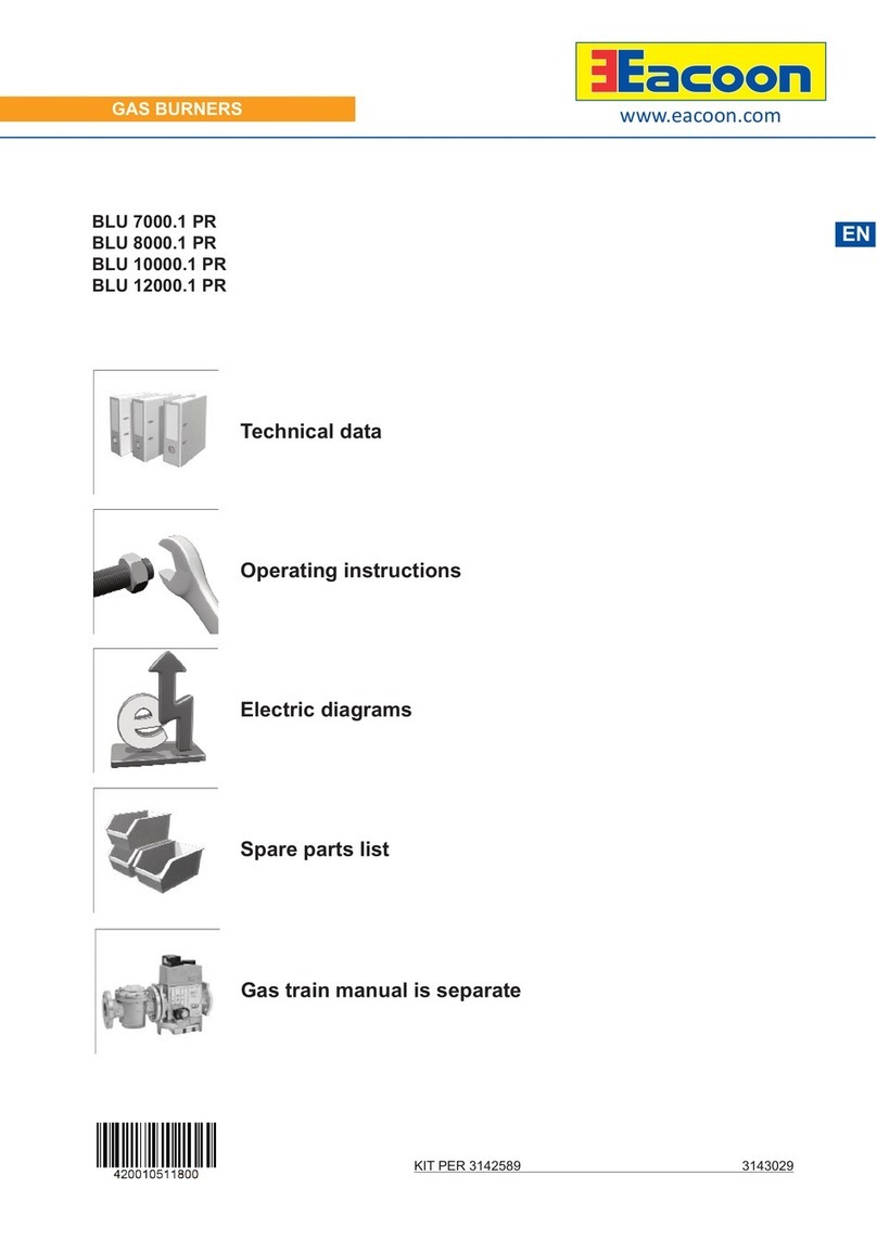
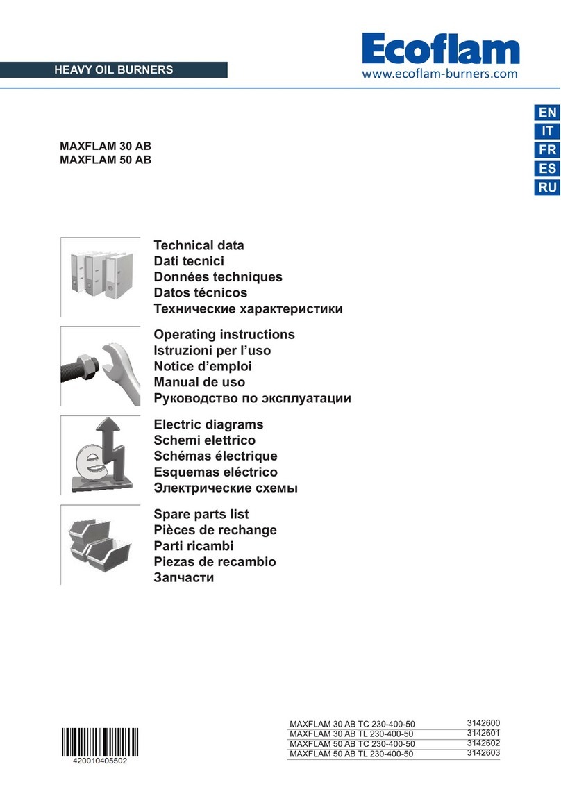
Technical data
Operating instructions
Electric diagrams
Spare parts list
www.ecoflamburners.com
LIGHT OIL BURNERS
EN
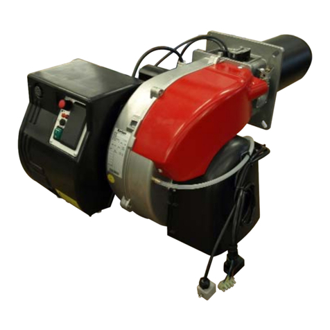
MAX 1
MAX 1 TC B10 230-50-60 TW 3142915
MAX 1 TL B10 230-50-60 TW
25-02-2021
www.ecoflam-burners.com
EN
420010518600
2
Conformity declaration EN 3
Technical data EN 4
Working diagram EN 5
Dimensions EN 6
Operating instructions for authorised specialists EN 7 - 18
Electric diagrams EN 19
Spare parts list EN 20 - 21
Overview - Index of contents
3
www.ecoflam-burners.com
EN
420010518600
Overview - Conformity declaration
4www.ecoflam-burners.com
EN
420010518600
Technical data MAX 1
Burner output
max/min kW - kcal/h
41,4 17,6
35604 15136
Oil throughput
max/min kg/h 3,5 1,5
Hydraulic system
1 stage 1
Regulating ratio 1:1
Fuel oil
Light oil (L.C.V. 10.200 kcal/kg max. visc 1,6÷6 mm2/s at 20°C)
(EL) Hu = 11,86 kWh/kg
Emission class Standard Class 2 - OIL EN267 (NOx < 185 mg/kWh)
Control box ARISTON E-BCU OIL
Air regulation
Air flap -
Flame monitor sensor
Ignition transformer danfoss / cofi
Fuel-oil pump danfoss / suntec
Electric motor
rpm - watt
2800 (3400) rpm
75 W
Voltage 230 V / 50 (60) Hz
Power consumption
(operation) 300 W
Weight 7 kg
Protection level IP40
Sound pressure
level dB(A) 60
Ambient temp. for storage -20°…+70° C
Temperature
for use -10°…+60° C
Overview - Technical data
5
www.ecoflam-burners.com
EN
420010518600
0
0,5
1
1,5
2
2,5
3
3,5
4
0 20 40 60 80 100 120 140
mbar
0 20 40 60 80 100 120
kW
kg/h
kcal/h*1000
0246810
Working diagram
The working diagram shows
burner output as a function of
combustion chamber pressure.
It corresponds to the maximum
values specified by EN 267
measured at the test fire tube.
The efficiency rating of the
boiler should be taken into
account when selecting a
burner.
Calculation of burner output:
QF = QN
ηK
QF = Burner output (kW)
QN = Rated boiler output (kW)
ηK= Boiler efficiency (%)
MAX 1
Overview - Working diagram
6www.ecoflam-burners.com
EN
420010518600
Overview - Dimensions
X
Y
Z
Packaging
MAX 1
Ø a
Ø b
Ø c
M
MAX 1
Model A B C D D1 E F G I L M
MAX 1 263 143 120 80 140 153 89 160 126,5 151,5 M8
Model Ø a Ø b Ø c
MAX 1 100 126,5 151,5
Model X Y Z Kg
MAX 1 310 400 320 7
Boiler plate drilling
A
BC
I
M
L
7
www.ecoflam-burners.com
EN
420010518600
Contents - Index - General warnings
Overview Conformity declaration 3
Technical data 4
Working diagram 5
Dimensions 6
Contents Index 7
General warnings 7
Conformity declaration 7
Burner description 8
Function General safety functions 9
E-BCU OIL control and safety unit 10
Oil burner pump 11
Installation Burner assembly 12
Electrical connection 13
Checks before commissioning 13
Oil feeding and suction line 14
Start up Setting data table - air regulation 15
Adjusting burner output 16
Oil pressure regulation 16
Service Maintenance 17
Troubleshooting 18
Overview Electrical diagrams 19
Spare parts list 20-21
Important notes
Ecoflam burners have been designed and
built in compliance with all current
regulations and directives.
All burners comply to the safety
and energy saving operation
regulations within the standard
of their respective performance
range.
The burner must not operate out-
side the working range.
The quality is guaranteed by a quality and
management system certified in
accordance with ISO 9001:2008.
MAX P burners are designed for the low-
pollutant combustion of light oil.
The burners comply with
standard EN267. Assembly and
commissioning must be carried
out only by authorised
specialists and all applicable
guidelines and directives must
be observed.
Burner description
MAX burners are one stage fully automatic
monoblock devices. Burner head is
designed to get the lowest emissions in
terms of NOx and unburnt particles in
order to maximize the heat generator
efficiency. Emissions can be different
respect to the ones recorded in the lab
because they depends a lot on the
generator on which the burner is fit.
The installer must comply with compulsory
rules. Avoid for instance dangerous
atmosphere or not ventilated rooms.
Packaging and handling
Move the burner still in its packaging using
a trolley or forklift, taking care not to drop it
and elevating it no more than 20cm from
ground level. After having removed the
packaging, check that the contents are in
WARNING
DANGER
WARNING
good condition and correspond with what
was ordered. If in doubt, contact the
manufacturer.
The burner must be installed by a
qualified individual.
If the weight and dimensions do not allow
for manual lifting, ask another operator for
help or use a forklift, harness the burner
using belts if no eyebolts are available.
Use the accessories provided
(flange, gasket, pins and nuts) to
install the burner onto the boiler,
taking care not to damage the
isolating gasket.
We can accept no warranty liability
whatsoever for loss, damage or injury
caused by any of the following:
- Inappropriate use.
- Incorrect assembly or repair by the
customer or any third party, including the
fitting of non-original parts.
- non authorised modifications made on
the burner.
Provision of the system and the
operating instructions
The firing system manufacturer must
supply the operator of the system with
operating and maintenance instructions on
or before final delivery. These instructions
should be displayed in a prominent
location at the point of installation of the
heat generator, and should include the
address and telephone number of the
nearest customer service centre.
Notes for the operator
The system should be inspected by a
specialist at least once a year. It is
advisable to take out a maintenance
contract to guarantee regular servicing.
WARNING
WARNING
BURNER SELECTION: Type of
operation and configuration must
be done by professional personnel
in order to grant correct working of
the burner. Installation, start-up and
maintenance must be carried out by
authorised specialists and all applicable
guidelines and regulations (including local
safety regulations and codes of practise)
must be observed.
Installation location
The burner must not be operated in rooms
containing aggressive vapours (e.g. spray,
perchloroethylene, hydrocarbon
tetrachloride, solvent, etc.) or tending to
heavy dust formation or high air humidity.
Adequate ventilation must be provided at
the place of installation of the furnace
system to ensure a reliable supply with
combustion air.
WARNING

8www.ecoflam-burners.com
EN
420010518600
A1 E-BCU OIL control box
M1 Electric motor for pump and
blower wheel
T1 Ignition transformer
Y Graduated rod
Y1 Solenoid valve
3 Air regulation in the burner head
5 Fastening screws for equipment plate
9 Wieland socket
15 Burner flange
16 Release knob
102 Fuel-oil pump
103B Air regulation
113 Air intake
3
113 103B
5
Y1
A1
M1 T1
15
16
102 9Y
Contents - Burner description
Scope of delivery
CB: COMPLETE BURNER
- 1 bag including :
- multilanguage technical manual.
- filter and hoses.
- wieland plug.
- nozzle and spanner.
- screws, nuts and washer.
KIT & ACS delivered separately
MAX 4 LN TC 230-50-60 TW
MAX Light oil
RANGE NAME BY FUEL TYPE
MAX 4 4 kg/h
MODEL SIZE (Gas: kW; Oil: kg/h)
1 stage
R 1 stage with preheather
OPERATION TYPE
MAX Low NOx Low NOx Class 3 yellow flame (<120 mg/kWh)
MAX Standard Class 2-OIL EN267 (<185 mg/kWh)
EMISSION COMBUSTION TYPE
TC Short head
TL Long head
HEAD TYPE
Light oil
KER Kerosene
BIODIESEL Biodiesel
B10 10 % Biodiesel
D Heavy oil: max visc. 50° E at 50°C
FUEL
230-50-60 230 Volt, 50-60 Hz
ELECTRICAL SUPPLY TO THE SYSTEM
CONFIGURATION ON REQUEST
HT High temperature version
TW Thermowatt
CONTROL BOX
15 14
9
www.ecoflam-burners.com
EN
420010518600
Function - General safety functions
Light oil pre-heating (version R)
If the system demands heat, the pre-
heater is switched on first.
When the oil preheating temperature is
reached, a thermostat in the pre-heater
activates the program sequence.
The heating time with cold start is
approximately 1 minutes.
Operating function
- If heat is requested by the boiler
regulator, the automatic oil combustion
control unit starts the program
sequence.
- The motor starts, the igniter is switched
on and the preventilation period of 15
seconds commences.
- During the preventilation period, the
furnace is monitored for flame signals.
- At the end of the preventilation period,
the fuel-oil solenoid valve opens and the
burner starts.
- The igniter remains switched off while
the burner is in operation.
Controlled shutdown
- Boiler thermostat interrupts heat
request.
- The fuel-oil solenoid valve closes and
the flame is extinguished.
- Burner motor switches off.
- Burner enters standby.
Safety function
A safety shutdown occurs:
- if a flame signal is present during
preventilation (parasitic flame
monitoring).
- if no flame is produced within 5 seconds
(safety time) of start-up (fuel
authorisation).
- if no flame is produced after an
unsuccessful restart attempt in the
event of flame failure during operation.
A safety shutdown is indicated by the
malfunction lamp lighting up and it is then
only possible to reenable the burner by
pressing the reset button after the cause
of the malfunction has been rectified.
For further information, see the
automatic combustion control unit
description.
M
M1
118
103
101
E4
T1
104
102
106
105
Y1
E4 Pre-heater (version R)
M1 Burner motor
T1 Ignition transformer
Y1 Solenoid valve
101 Blower / Fan
102 Oil pump
103 Air damper
104 Oil pressure regulator
105 Hoses
106 Filter
118 Nozzle
10 www.ecoflam-burners.com
EN
420010518600
The E-BCU OIL fuel oil control and safety
unit controls and monitors the forced
draught burner. The microprocessor-
controlled program sequence ensures
maximum stability of time periods,
regardless of fluctuations in the power
supply or ambient temperature. The
design of the automatic combustion
control unit protects it from the effects of
brownouts. Whenever the supply voltage
drops below its rated minimum level (170
V), the control unit shuts down - even in
the absence of a malfunction signal. The
control unit switches itself back on again
once the voltage has exceeded the 178 V.
R-Reset button + lock-out led.
RJ45 - Connector for PC interface
(diagnostic, separate item).
!Always disconnect the power supply before installing or removing the control unit.
Do not attempt to open or carry out repairs
on the control unit.
Function - E-BCU OIL control and safety unit
KIT E-BCU
DIAGNOSTIC TOOL
(not supplied)
1
< 400s17s 5s
5s
5s--- -< 1s
23 44’56 789
LINE
C
Locking and unlocking the system
The control unit can be locked (switched
to malfunction) and unlocked (malfunction
cleared) by pressing the R reset button,
provided the system is connected to the
mains power supply.
Symbol Designation
Waiting for heat request
Waits for pre-heater (for burner with pre-heater)
Burner motor on
Start of ignition
Flame present
R
RJ45
11
www.ecoflam-burners.com
EN
420010518600
Function - Oil burner pump
1 suction intake connection.
2 return connection.
3 pressure connection.
4 oil pressure gauge connection.
5 negative pressure gauge connection.
6 oil pressure regulator.
10 Solenoid valve electrical connection.
Y1 fuel-oil solenoid valve.
21
4
5
6
3
10
Y1
DANFOSS 
BFP 11 R3
The oil burner pump used is a self-priming
gear pump, which must be connected as
two-line pump via a bleed filter. There is an
intake filter and an oil pressure regulator
integrated in the pump. Pressure gauges
for pressure measurements and negative
pressure measurements must be
connected before the equipment is
commissioned.
NB: before starting the burner, check that
the return pipe is open. An eventual
obstraction could damage the pump
sealing device.
3
2
1
1
1 Hoses
2 Filter
3 Oil cock
4 Plug
One-pipe system
ONE PIPE SYSTEM: If the oil supply
circuit is one-pipe system, the pump
needs to be modified following intructions
in the picture.
3
2
1
Without horse-shoe�
-shaped washer.
1 - 2
Two-pipe system
With horse-shoe�
-shaped washer.
4
1- 2
12 www.ecoflam-burners.com
EN
420010518600
Installation - Burner assembly
Oil connection
The filter must be located in such a way
that the correct hose routing cannot be
impaired. The hoses must not kink.
Burner assembly
The burner is fixed by mean of connecting
flange and therefore to the boiler.
Installation:
• To fix the flange 3to the boiler with
the screws 4.
• Turn the burner slightly, guide it into
the flange and secure using screw 5.
Removal:
• Loosen screw 5.
• Turn the burner out and pull it out of
the flange.
Burner blast tube insertion depth and
brickwork
Unless otherwise specified by the boiler
manufacturer, heat generators without a
cooled front wall require brickwork or
insulation 5 as shown in the illustration.
The brickwork must not protrude beyond
the leading edge of the blast tube, and
should have a minimum conical angle of
60°. Gap 6 must be filled with an elastic,
non-combustible insulation material. For
boilers with reverse firing, the minimum
burner tube insertion depth A as specified
in the boiler manufacturer’s instructions
must be observed.
On boilers the blast tube insertion depth
should be observed as per the boiler
manufacturer's instructions.
Reverse flame boiler :
A = 50-100 mm.
Three pass boilers :
A1 = 50-100 mm.
Exhaust system
To avoid unfavourable noise emissions,
right-angled connectors should not be
used on the flue gas side of the boiler.
A
A1
1
3
4
2
–
+
3
5
13
www.ecoflam-burners.com
EN
420010518600
Installation - Electrical connection - Checks before commissioning
Electrical connection
The electrical installation and connection
work must only be carried out by an
authorised electrical specialist.
All applicable rules and regulations must
be observed.
The electrical installation should include a
type A circuit breaker.
The applicable guidelines and
directives must be observed, as well as
the electrical circuit diagram supplied
with the burner!
• Check to ensure that the power supply
voltage is as specified in the electric
diagram and in data plate.
• Burner fuse: 5 A.
Checks before commissioning
The following must be checked before
initial commissioning:
• That the burner is assembled in
accordance with the instructions given
here.
• That the burner is pre-set in accordance
with the values in the adjustment table.
• Setting the combustion components.
• The heat generator must be ready for
operation, and the operating regulations
for the heat generator must be observed.
• All electrical connections must be correct.
• The heat generator and heating system
must be filled with water and the
circulating pumps must be in operation.
• The thermostats, pressure regulator, low
water detectors and any other safety or
limiting devices that might be fitted must
be connected and operational.
• The exhaust gas duct must be
unobstructed and the secondary air
system, if available, must be operational.
• An adequate supply of fresh air must be
guaranteed.
• The heat request must be available.
• Fuel tanks must be full.
• The fuel supply lines must be
assembled correctly, checked for leaks
and bled.
• A standard-compliant measuring point
must be available, the exhaust gas duct
up to the measuring point must be free of
leaks to prevent anomalies in the
measurement results.
1
Electrical connection (plug-in)
It must be possible to disconnect the
burner from the mains using an
omnipolar shutdown device complying
with the standards in force. The burner
and heat generator (boiler) are connected
by a 7-pin connector (fig.1).
Position of electrodes
Note: Always check the position of
electrodes after having replaced the
nozzle (see illustration). A wrong position
could cause ignition troubles.
3mm
3/4mm
4mm
1
14 www.ecoflam-burners.com
EN
420010518600
H
H
(m) ø 6 mm ø 10 mm
0,5
1
1,5
2
2,5
3
3,5
15
13
11
9
7
5
-
100
99
84
68
53
37
22
H
(m) ø 6 mm ø 10 mm
0,5
1
1,5
2
2,5
3
3,5
19
21
23
25
27
29
31
ø 8 mm
47
41
34
28
22
15
9
ø 8 mm
60
66
72
79
85
91
98
100
100
100
100
100
100
100
y
H = x-y
x
Burner
lower
than
tank FEEDING
LINE
WITH
DANFOSS
BFP21
Burner higher than tank
N.B. = X < 20 m
Y must be kept as lower as possible in order to avoid cavitation. Anyway Y< 4 m.
Installation - Oil feeding and suction line
Burner lower than tank
Burner higher than tank Length pipe (m)
Length pipe (m)
FEEDING LINE WITH DANFOSS BFP11 R3
Correction of altitude
Pump in suction (H +) or charging (H -)
Altitude (m) Theoretical H (m)
0-500 0
501-800 0,5
801-1300 1,0
1301-1800 1,5
1801-2200 2,0
e.g.: altitude 1100m Theoretical H = 1m actual H 2m, Corrected H for suction 2 + 1 = 3m Corrected H for charging 2 - 1 = 1m.
Choose the Ø of the piping from the table, based on the length expanded between the tank and pump. If corrected H for suction
exceeds 4m; make provisions for a transfer pump (max. pressure 2 bar).
!The length of the tubes apply to
burners powered by 50 Hz mains
electricity; in case of 60 Hz power,
divide the relevant lengths by 1.5.
15
www.ecoflam-burners.com
EN
420010518600
A
+
-
Start up - Setting data table - Air regulation
The settings above are basic settings.
These adjustment values are normally
suitable for commissioning the burner.
These values have been determined in
our test labs and are useful for the first
switch-on as final setting must be done
using a combustion analyzer.
Favourable combustion values can be
achieved using the following nozzles:
DANFOSS H÷S 80°÷60°
DELAVAN W 60°
STEINEN S 60°
NOZZLE PUMP OUTPUT FIRING HEAD SETTING AIR DAMPER SETTING AIR SELECTOR
gph spry bar kg/h Pos. Pos. Pos.
0,55 80°S 10 1 3 -
MAX 1
Air damper setting (A).
To act on the screw in figure:
• to increase output, turn screwdriver
clockwise
• to reduce output, turn screwdriver
counterclockwise
Firing head setting (B).
To act on the screw in figure:
• turn Allen key till you reach the
requested value (index 0-4,5).
MAX 1
+
-
+
-
B
MAX 1
16 www.ecoflam-burners.com
EN
420010518600
Start up - Adjusting burner output - Oil pressure regulation
Burner start
Before starting the burner, draw oil in until
the filter is completely filled.
Then start the burner by switching on the
boiler regulator. Open the bleed screw on
the oil filter to allow the oil line to bleed
fully during the preventilation phase. The
negative pressure must not fall below 0.4
bar. Close the bleed screw when the filter
is completely filled with oil and oil is
flowing out without bubbles.
Burner output adjustment
Use the pressure regulator to adjust the oil
pressure in accordance with the burner
output desired. Monitor the combustion
values continuously as you do so (CO,
CO2, soot test). Adjust the airflow
gradually if necessary. 1 suction intake connection.
2 return connection.
3 pressure connection.
4 oil pressure gauge connection.
5 negative pressure gauge connection.
6 oil pressure regulator.
10 Solenoid valve electrical connection.
Y1 fuel-oil solenoid valve.
Optimising combustion values
If the combustion values are not
satisfactory modify the position of the
combustion head. By doing this the burner
ignition conditions and the combustion
values change. Compensate for the
change in airflow if necessary by adjusting
the air flap position.
Note: observe the minimum required
flue gas temperature specified by the
boiler manufacturer and the
requirements demanded of flue gas
ducts for avoiding condensation.
Oil pressure regulation
The oil pressure, and therefore burner
output, is adjusted using oil pressure
regulator 6in the pump.
Turn to
- right: to increase pressure
- left: to reduce pressure
Connect a pressure gauge at point 4(with
R1/8" thread).
Checking negative pressure
The vacuum meter for checking negative
pressure must be connected to point 5,
R1/8". Maximum permissible negative
pressure is 0.4 bar. At higher negative
pressures, the fuel oil gasifies, which
causes scraping noises in the pump and
ultimately leads to pump damage.
Cleaning the pump filter
The filter is located under the pump
cover(SUNTEC) or in appropriate
cartridge(DANFOSS). To be able to clean
the filter, it is necessary to loosen the
screws and remove the cover first
(SUNTEC) or to unscrew the screw
(DANFOSS).
• Check the pump cover seal and replace
the gasket if necessary.
Operating check
Flame monitoring must be checked for
safety as part of initial commissioning and
also after servicing or if the system has
been out of operation for any significant
period of time.
- Starting attempt with flame monitor unlit:
the automatic combustion control unit
must switch to malfunction at the end of
the safety time
- Start with flame monitor lit: the
automatic combustion control unit
must switch to malfunction after 10
seconds of preventilation
- Normal start-up: flame monitor goes out
when burner in operation; the automatic
combustion control unit must switch to
malfunction after the restart and end of
the safety time
!Risk of air blast!
Continuously check CO, CO2and soot emissions when adjusting the output of
the burner. Optimise combustion values in the event of CO formation. CO must
not exceed 50 ppm.
21
4
5
6
3
10
Y1
DANFOSS 
BFP 11 R3
17
www.ecoflam-burners.com
EN
420010518600
Service - Maintenance
Fan assembly
Observe the positioning diagram below
when replacing the motor and blower
wheel. The inside flange Aof the blower
wheel must be fitted at the same level as
the equipment plate B. Insert a straight
edge between the wing of the blower wheel
and set Aand Bto the same height, tighten
the set screw on the blower wheel
(maintenance position 1).
Burner and boiler servicing must only
be carried out by qualified personell.
The system operator is advised to take
out a service contract to guarantee
regular servicing.
Attention
• Disconnect the electrical supply before
carrying out any maintenance or
cleaning work.
• The blast tube and firing head may be
hot.
Checking the exhaust gas temperature
• Check the flue gas temperature at
regular intervals.
• Clean the boiler if the flue gas
temperature is more than 30°C above
the value measured at the time of
commissioning.
• To simplify the check, use a flue gas
temperature indicator.
Maintenance on the burner
Maintenance 1
• Clean fan and housing and check for
damage.
Maintenance 2
• Check and clean the combustion head.
• Replace oil nozzle.
• Check ignition electrodes, readjust or
replace as necessary.
• Fit combustion head. Observe
adjustment dimensions.
• Fit burner.
• Start burner, check flue gas data, correct
burner settings if necessary.
Maintenance 3
• Check oil supply components (tubes,
pumps, oil feed tube) and their
connections for leaks or signs of wear,
replace if necessary.
• Check electrical connections and
connection cables for damage, replace if
necessary.
• Check pump filter and clean if
necessary.
Nozzle and cleaning replacement
Use only the suitable box wrench provided
for this operation to remove the nozzle,
taking care to not damage the electrodes.
Fit the new nozzle by the same care.
Note: Always check the position of
electrodes after having replaced the
nozzle (see illustration). A wrong position
could cause ignition troubles.
Max 1
2
–
+
3
5
18 www.ecoflam-burners.com
EN
420010518600
Fault diagnosis and repair
In the event of a malfunction, first check
that the prerequisites for correct operation
are fulfilled:
1. is the system connected to the power
supply?
2. is there oil in the tank?
3. are all shut-off valves open?
4. are all control and safety devices,
such as the boiler thermostat, low-water
detector, limit switch, etc.
adjusted correctly?
If the malfunction persists, use the
following table.
It is not permitted to repair any
components relevant to safety. These
components must be replaced by parts
with the same order number.
Only use original spare parts.
NB: after each operation:
• under normal operating conditions
(doors closed, hood fitted, etc.), check
combustion and check the individual
lines for leaks.
• Record the results in the relevant
documents.
E-BCU display interface must be used
to read the faults by service personell.
Service - Troubleshooting
Symbol fault Fault Cause Remedy
No heat request Thermostats defective or
incorrectly adjusted Adjust the thermostats, replace if necessary.
Sullply voltage lower than
minimum allowed value
Drop in supply voltage or
power failure.
Control unit malfunction
Check the cause of the fall in voltage or the
power failure.
Replace the control unit.
Burner starts at switch-on
for very short period and
then shuts down and the red
LED lights up
The control unit has been
intentionally locked Reset control unit.
Burner starts and then
shuts down after
preventilation
Flaring during pre-ventilation or
pre-ignition
Check ignition sparks/adjust or replace
electrode
Check/replace fuel-oil solenoid valve
Burner starts and then shuts
down after the solenoid
valves have opened
No flame signal at end of
safety time
Check the oil level in the tank.
Top tank up as required.
Open the valves.
Check the oil pressure and the operation of
the pump, coupling, filter, solenoid valve.
Check ignition circuit, electrode adjustment.
Clean/replace electrodes.
Clean/replace flame monitor.
Replace the following items as required:
Ignition electrodes/ignition cables/ignition
transformer/nozzle/pump/solenoid valve/
automatic combustion control unit.
Flame extinguishing
during operation
Flame goes out during
operating phase
19
www.ecoflam-burners.com
EN
420010518600
Overview - Electric diagrams
20 www.ecoflam-burners.com
EN
420010518600
MAX 1
19
4
12
9
1011
8
33
2825
26
22
27
23
17
20
34
34
35
1516
13
21
29
30
2
3
1
5
6
18
24
14
14.1
Overview - Spare parts list

Other manuals for MAX 1

2

Other Ecoflam Burner manuals

Ecoflam BLU 500.1 PR User manual

Ecoflam

Ecoflam BLU 500.1 PR User manual

Ecoflam MAX GAS 70 PR User manual

Ecoflam

Ecoflam MAX GAS 70 PR User manual

Ecoflam MAX P 45 AB User manual

Ecoflam

Ecoflam MAX P 45 AB User manual

Ecoflam BLU 500.1 LN PR TC MET.SR 230/400/50 User manual

Ecoflam

Ecoflam BLU 500.1 LN PR TC MET.SR 230/400/50 User manual

Ecoflam Multicalor 170.1 P AB User manual

Ecoflam

Ecoflam Multicalor 170.1 P AB User manual

Ecoflam MAX P 35 AB User manual

Ecoflam

Ecoflam MAX P 35 AB User manual

Ecoflam MULTICALOR 70 PRE User manual

Ecoflam

Ecoflam MULTICALOR 70 PRE User manual

Ecoflam MAX GAS 350 PAB TC User manual

Ecoflam

Ecoflam MAX GAS 350 PAB TC User manual

Ecoflam MAIOR P 300 AB User manual

Ecoflam

Ecoflam MAIOR P 300 AB User manual

Ecoflam Multicalor 170.1 User manual

Ecoflam

Ecoflam Multicalor 170.1 User manual

Ecoflam MAX GAS 170 LN P TC SGT 230-50 TW User manual

Ecoflam

Ecoflam MAX GAS 170 LN P TC SGT 230-50 TW User manual

Ecoflam BLU 1500.1 PAB User manual

Ecoflam

Ecoflam BLU 1500.1 PAB User manual

Ecoflam Multicalor 700.1 MD User manual

Ecoflam

Ecoflam Multicalor 700.1 MD User manual

Ecoflam AZUR 40 User manual

Ecoflam

Ecoflam AZUR 40 User manual

Ecoflam Multiflam 700.1 PR User manual

Ecoflam

Ecoflam Multiflam 700.1 PR User manual

Ecoflam MAX 20 D HT User manual

Ecoflam

Ecoflam MAX 20 D HT User manual

Ecoflam BLU 1700.1 P AB User manual

Ecoflam

Ecoflam BLU 1700.1 P AB User manual

Ecoflam MAX 15 TC HT 230-50 TW VC User manual

Ecoflam

Ecoflam MAX 15 TC HT 230-50 TW VC User manual

Ecoflam Multicalor 45 User manual

Ecoflam

Ecoflam Multicalor 45 User manual

Ecoflam Multicalor 300.1 PR User manual

Ecoflam

Ecoflam Multicalor 300.1 PR User manual

Ecoflam MAIOR P 45 User manual

Ecoflam

Ecoflam MAIOR P 45 User manual

Ecoflam Maior P 150.1 PR User manual

Ecoflam

Ecoflam Maior P 150.1 PR User manual

Ecoflam BLU 15000.1 PR User manual

Ecoflam

Ecoflam BLU 15000.1 PR User manual

Ecoflam DUNGS SV-SVDLE User manual

Ecoflam

Ecoflam DUNGS SV-SVDLE User manual

Popular Burner manuals by other brands

Riello 40 FS20 Installation, use and maintenance instructions

Riello

Riello 40 FS20 Installation, use and maintenance instructions

Twin Heat COMPACT STOKER Cpi12 instructions

Twin Heat

Twin Heat COMPACT STOKER Cpi12 instructions

Riello 20072969 Installation, use and maintenance instructions

Riello

Riello 20072969 Installation, use and maintenance instructions

Honeywell Q349A Series instruction sheet

Honeywell

Honeywell Q349A Series instruction sheet

Beckett AFII user manual

Beckett

Beckett AFII user manual

Integra FIREBOY eco operating instructions

Integra

Integra FIREBOY eco operating instructions

Riello P 200 P/G Series Installation, use and maintenance instructions

Riello

Riello P 200 P/G Series Installation, use and maintenance instructions

Midco economite RE6700B Installation and service instructions

Midco

Midco economite RE6700B Installation and service instructions

Riello RDB2.2 BG1 BLU 16 kW Installation, use and maintenance instructions

Riello

Riello RDB2.2 BG1 BLU 16 kW Installation, use and maintenance instructions

baltur TBML 90P Instruction manual for installation, use and maintenance

baltur

baltur TBML 90P Instruction manual for installation, use and maintenance

Riello RS 28/M Installation, use and maintenance instructions

Riello

Riello RS 28/M Installation, use and maintenance instructions

Deni 16310 Use and care instructions

Deni

Deni 16310 Use and care instructions

Limpar WKB 750 operating manual

Limpar

Limpar WKB 750 operating manual

Pelltech PV 20a user manual

Pelltech

Pelltech PV 20a user manual

baltur BT 40 DSN 4T Instructions for use

baltur

baltur BT 40 DSN 4T Instructions for use

Riello GAS 6 Installation, use and maintenance instructions

Riello

Riello GAS 6 Installation, use and maintenance instructions

Riello RL 250 manual

Riello

Riello RL 250 manual

Dantherm RG3D manual

Dantherm

Dantherm RG3D manual

manuals.online logo
manuals.online logoBrands
  • About & Mission
  • Contact us
  • Privacy Policy
  • Terms and Conditions

Copyright 2025 Manuals.Online. All Rights Reserved.