Andover Controls RoamIO User manual

RoamIO
User’s Guide

2003, Andover Controls Corporation
All Rights Reserved
No part of this publication may be reproduced, read or stored in a retrieval
system, or transmitted, in any form or by any means, electronic, mechanical,
photocopying, recording, or otherwise, without prior written permission of
Andover Controls Corporation.
Produced in the United States of America.
Infinity, Continuum and CyberStation are trademarks of Andover Controls Corporation.
All other trademarks are the property of their respective owners.
RoamIO User’s Guide, Version: A January, 2003
Andover Controls part number: 30-3001-845
The information in this book is furnished for informational purposes only, is
subject to change without notice, and should not be construed as a commitment
by Andover Controls Corporation. Andover Controls Corporation, assumes no
liability for any errors or inaccuracies that may appear in this document.
Andover Controls Corporation
300 Brickstone Square
Andover, MA 01810
(978) 470-0555
fax: (978) 470-0946

RoamIO User’s Guide III
Radio Interference
This equipment has been tested and found to comply with the limits for a Class A digital device,
pursuant to FCC CFR47 Part 15, EN55022, AS/NZS3548 and VCCI requirements. These limits
are designed to provide reasonable protection against harmful interference when the equipment is
operated in a commercial environment. This equipment generates, uses, and can radiate radio
frequency energy and, if not installed and used in accordance with the instructions in this manual,
may cause harmful interference to radio communications. Operation of this equipment in a
residential area is likely to cause harmful interference in which case the user will be required to
correct the interference at his own expense.
Note
This digital apparatus does not exceed the Class A limits for radio noise emissions from digital
apparatus set out in the Radio Interference Regulations of the Canadian Department of
Communications.
Avis
Le présent appareil numérique n’émet pas de bruitsradioélectriques dépassant les limites
applicables aux appareilsnumériques de la classe A prescrites dans le Règlement sur le brouillage
radioélectrique édicté par le ministère des Communications du Canada.

iv Andover Controls Corporation

RoamIO User’s Guide v
Contents
System Overview....................................................................................... 1
Before You Get Started ............................................................................. 2
Hardware and Software Requirements...................................................... 2
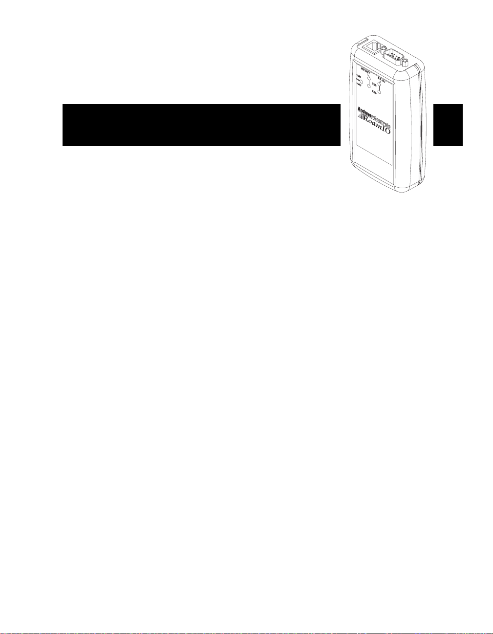
RoamIO Hardware..................................................................................... 3
Batteries and Power....................................................................................3
Connectors and Indicators ..........................................................................4
DB-9 Connector Pinout ...............................................................................4
Connecting to Controllers/Sensors..............................................................5
RoamIO Software Installation .................................................................... 6
Connect P/PC and RoamIO to the Infinet Controller.................................10
Using RoamIO ..........................................................................................11
Logging On/Preferences ...........................................................................11
Using the RoamIO Explorer Tree ..............................................................15
Editing Controllers ............................................................................16
CX Controller ............................................................................................. 17
Infinet Controller......................................................................................... 20
About Points .............................................................................................22
Types of Points .........................................................................................22
Hardware-Defined Points ..........................................................................22
Input Points................................................................................................ 22
Output Points ............................................................................................. 23
Viewing a Point List.................................................................................... 23
Input and Output Points.............................................................................. 24
Log Tab-All Points...................................................................................... 30
Xdriver Tab-All Points................................................................................. 33
Software-Defined Points............................................................................34
Numeric Points........................................................................................... 35
Date Time Points........................................................................................ 38
String Points............................................................................................... 40
Updating i2 Firmware................................................................................41
Overview...................................................................................................41
I2 Update Procedure.................................................................................41
Logging Off ...............................................................................................46

vi Andover Controls Corporation

RoamIO User’s Guide 1
RoamIO
Hand-Held Service Tool
This manual describes the installation, care and use of the RoamIO Hand-Held Service
Tool Interface.
System Overview
The RoamIO Hand-Held Service Tool (hereafter referred to as RoamIO) is a small,
battery-powered portable device that connects a laptop PC or Pocket PC (hereafter
referred to as P/PC) to the service port of any Infinet controller. A P/PC running the
RoamIO software application has the following features and capabilities:
• Equivalent DBSync functionality to the LSX280
• Firmware upgrading for i2 controllers.
• Point editors for editing:
o Controllers
o Inputs
o Outputs
o Numerics
o DateTime
o Strings
o System Variables
o Comm Ports
Note: Each RoamIO connected to the Infinet bus (up to a maximum of four at any given
time, including any LSX 280’s that may be connected) is assigned an InfinetID between
251 and 254.

2 Andover Controls Corporation
Before You Get Started
Before you get started, ensure that you have all of the following items:
• RoamIO and interface cables
• P/PC with serial cable and docking cradle
• Desktop PC or Laptop PC
• RoamIO software application
Hardware & Software Requirements
Before installing the RoamIO application, ensure that your P/PC and desktop or laptop
PC meet the following requirements:
Desktop or Laptop PC Hardware Requirements
Minimum Recommended
Any Hardware that is compatible with
ActiveSync 3.5
Any Hardware that is compatible with
ActiveSync 3.5
CD ROM Drive or access to
installation over a network
CD ROM Drive or access to
installation over a network
Available 9-pin or 25-pin
communications port, OR USB port
Available 9-pin communications port,
OR USB port
Desktop or Laptop PC Software Requirements
Minimum Recommended
ActiveSync 3.5 ActiveSync 3.5
Any Operating System that is
compatible with ActiveSync
Any Operating System that is
compatible with ActiveSync
P/PC Requirements
Minimum Recommended
PocketPC2002 Operating System PocketPC2002 Operating System
32 MB RAM 64 MB RAM
9-pin RS 232 serial cable to comm
port on P/PC.
9-pin RS 232 serial cable to comm
port on P/PC.
Note: The ActiveSync software is included as part of the P/PC package and is part of the
installation & configuration of the P/PC itself. Refer to the documentation supplied with
your P/PC for requirements, installation and operation of the ActiveSync program.

RoamIO User’s Guide 3
RoamIO Hardware
The RoamIO serves as an interface between the Infinet bus and the P/PC. It consists of
a battery powered hand-held unit and a set of cables. The RoamIO connects between the
serial port of the P/PC and the service port of the Infinet controller.
Batteries and Power
Power is supplied via two AA type batteries (included). Recommended batteries are
Eveready X91 1.5V AA alkaline or equivalent. The battery compartment is located on the
back of the unit. To avoid damaging the unit, slide the power switch to the OFF position
before installing or removing batteries. During installation, be sure to observe correct
polarity when inserting batteries. Align the + and – symbols printed on the batteries with
the symbols indicated inside the battery compartment.
To apply power to the unit, slide the power switch to the ON position. The Power indicator
illuminates indicating that the batteries are fully operational. A new set of alkaline
batteries provides up to 50 hours of continuous use depending on the battery
manufacturer. To prolong battery life the RoamIO is designed to draw power from the i2
controller (once connected) instead of continuing to draw power from the batteries.
To further prolong battery life, the RoamIO goes into “Sleep Mode” after five minutes of
inactivity. Sleep mode is when some of the RoamIO internal circuitry powers down and
awaits the receipt of data from the P/PC to bring the RoamIO out of sleep mode and back
to normal operation. The power status LED briefly flashes every two seconds while in
sleep mode.
When the batteries are within 5% of their original voltage, the Power indicator (PWR)
flashes to indicate the batteries need to be replaced.
Battery
Compartment
Power
Switch

4 Andover Controls Corporation
Connectors and Indicators
The following diagram illustrates the connector and indicator areas of the interface unit.
DB-9 Connector Pinout
The following table shows the DB-9 connector pinout on the RoamIO.
Pin Signal
2 RXD (Received Data)
3 TXD (Transmitted Data)
5 GND (Ground)
Pin 9 Pin 6
Pin 5 Pin 1

RoamIO User’s Guide 5
Connecting To Controllers/Sensors
There are three different styles of service port connectors found on Andover Control’s
Infinet controllers. The cable set that is supplied with the RoamIO product is designed to
accommodate all styles.
The following diagram depicts the use of the cable set for interfacing to the controller.
Part Number
01-0100-315
01-0100-435
01-0100-476

6 Andover Controls Corporation
RoamIO Software Installation
This section describes how to install the RoamIO software application onto a P/PC. To
install the RoamIO application onto your P/PC, perform the following steps:
1. Place the P/PC in the docking cradle that is connected to your laptop or desktop PC.
(Refer to the documentation supplied with your P/PC for operation and detailed
information)
2. Once the desktop PC and the P/PC are properly synchronized, run the RoamIO
setup from the installation CD.
3. When the e-Pocket Setup Wizard screen appears, click Next to proceed.

RoamIO User’s Guide 7
4. Read the information on the License Agreement screen. After accepting the
agreement, click Next to continue.
5. Select a directory and start menu folder on your desktop PC to install the RoamIO to
and click Next.

8 Andover Controls Corporation
6. Verify the Destination directory and Start Menu folder are correct. Click Install to
begin the installation.
7. During the installation, a verification dialog appears. Click Yes to install the RoamIO
software application onto the PocketPC.

RoamIO User’s Guide 9
8. Once the application finishes installing onto the PocketPC, click Finish.

10 Andover Controls Corporation
Connecting P/PC and RoamIO to the Infinet Controller
Once the RoamIO software application is installed onto the P/PC, the next step is
connecting to the Infinet controller. Connect the serial port of the PocketPC to the
RoamIO using an RS-232 adapter. The connector on the RoamIO is a standard DB-9
male connection. Using an appropriate combination of cables and adapters (actual
connections and cable usage is explained in the hardware section of this document),
connect the RoamIO to any Infinet controller’s service port.
RoamIO
Adapter cable
connected to an
Infinet controller’s
service port (see
page 5).
Pocket PC
(P/PC)
DB-9
Connector
(see page 4)
RJ-11
Connector
Infinet Bus
i2 Controller
i2 Controller
Infinet
Controller
Infinet
Controller
Stylus

RoamIO User’s Guide 11
Using RoamIO
Once the P/PC and RoamIO are connected to the Infinet controller and the RoamIO is
powered on, the RoamIO software application can communicate with the Infinet
controller. The next section introduces you to the following features of the RoamIO
software application:
• Logging on
• Using the RoamIO explorer tree
• About points
• i2 firmware upgrade
• Logging off
Logging on/Preferences
To logon to the Infinet controller, perform the following steps:
1. Using your stylus, open the Start menu on your P/PC and select RoamIO.

12 Andover Controls Corporation
2. The RoamIO splash screen appears. Tap the screen with your stylus to close the
splash screen and enter the program.
3. The RoamIO menu bar appears at the bottom of the PocketPC screen. With the
stylus, tap Tools to bring up the tools menu.
Preferences Displays a configuration window that determines the
P/PC COMM port, what to display in the explorer tree
and how to display it.
UpRev I2
Controllers
Initiates the process for updating the firmware on i2
controllers as described on page 41.

RoamIO User’s Guide 13
4. From the Tools menu, use your stylus to tap Preferences.
Use the options on the preferences dialog to configure the RoamIO as follows:
RoamIO Commport The PocketPC Commport (COM1 through COM5) the
RoamIO will communicate with.
Note: The commport must be selected before trying to
connect.
Filter: Show only… Select individual objects to display: Inputs, Outputs,
Numerics, Infinet Controllers, Date Time, Strings,
ComPorts, and System Vars objects are available.
Select None to remove all check marks or select All to
put check marks next to all objects.
Automatically fill
folders
Places latest data points into applicable folders on the
explorer tree (page 15).
Open folders while
filing
Displays all folders in an open condition on the explorer
tree. Only available with “Automatically fill folders”
selection (above).
Put Infinet Ctrls in
a folder
Places any Infinet controllers in a folder labeled “Infinet
Controllers” on the explorer tree.
Restore Refreshes the screen with the values currently stored in
the PocketPC. This button will be grayed out until
changes are made.
OK Closes the window after changing the preferences.
Cancel Closes the window without changing the preferences.

14 Andover Controls Corporation
5. Tap OK to return to the main menu.
6. Using your stylus tap File to open the connect menu.
7. With your stylus tap Connect to establish communications between the PocketPC
and the Infinet bus through the Infinet controller.
8. The Logon dialog appears. Enter your username and password and tap OK to
logon.
Once logged in, the Connect selection on the File menu is replaced with a Disconnect
selection. Use it to disconnect and logon as a different user.
Table of contents