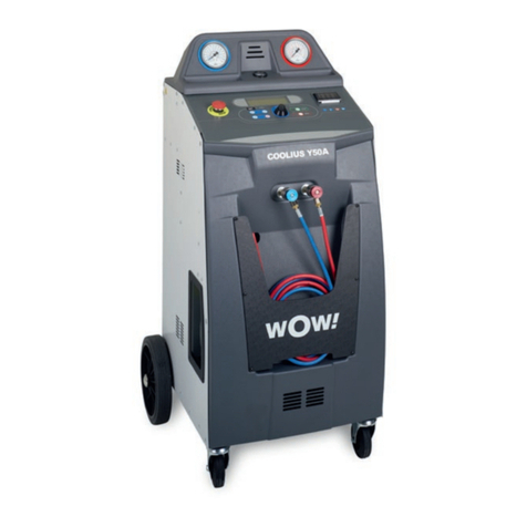
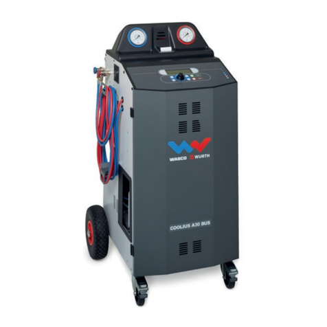
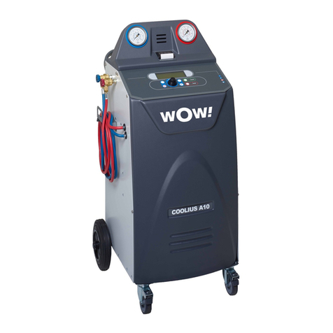
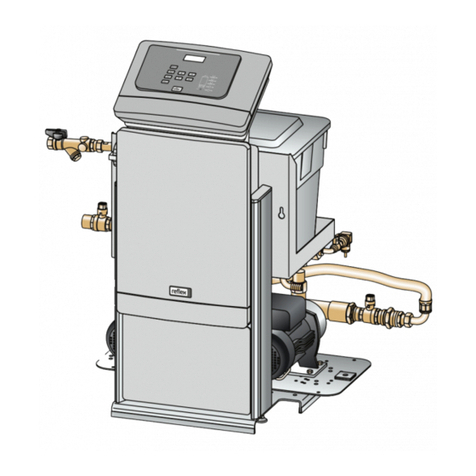
COOLIUS Y50A Product guide

Original Manual
Service book
Y50A
A/C Service-Unit for refrigerant R1234yf
with integrated refrigerant analyzer
Doc.No.: 225802_Rev.03.01

2COOLIUS Y50A

3COOLIUS Y50A
Contents
1 Flow diagram ..................................................................................................................................................................................4
1.1 Flow diagram without Refrigerant analyzer circuit ......................................................................................................4
1.1 Flow diagram - SPARE PARTS LIST...............................................................................................................................5
1.2 Refrigerant analyzer circuit..................................................................................................................................................6
1.2 Refrigerant analyzer circuit - SPARE PARTS LIST.....................................................................................................7
2 Electric diagram ............................................................................................................................................................................8
2.1 Electric diagram - SPARE PARTS LIST..........................................................................................................................9
3 Machine .......................................................................................................................................................................................... 10
3.1 Machine - SPARE PARTS LIST.......................................................................................................................................11
3.2 Manifold - SPARE PARTS LIST...................................................................................................................................... 12
3.3 Other parts - SPARE PARTS LIST................................................................................................................................. 13
3.4 Accessories - SPARE PARTS LIST............................................................................................................................... 13
4 Refrigerant analyzer................................................................................................................................................................. 14
4.1 Refrigerant analyzer - SPARE PARTS LIST............................................................................................................... 15
4.2 Refrigerant analyzer error codes.................................................................................................................................... 16
4.3 Filter replacement................................................................................................................................................................. 17
4.3.1 Externalwhitelterreplacement............................................................................................................................. 17
4.3.2 Coalescentlterreplacement................................................................................................................................... 17
4.3.3 Refrigerantanalyzerlter/owrestrictorreplacement(NEUTRONICSoriginalspareparts)......... 19
4.4 Air sensor replacement ...................................................................................................................................................... 20
Removing the Air sensor ........................................................................................................................................ 20
Replacing the Air sensor......................................................................................................................................... 20
5 Maintenance................................................................................................................................................................................. 21
5.1 Filter and vacuum pump oil replacement .................................................................................................................... 21
5.1.1 Replacingthelter........................................................................................................................................................ 21
5.1.2 Replacing the vacuum pump oil .............................................................................................................................. 22
5.2 Counterreset(UNLOCKCODErequired) .................................................................................................................. 23
6 Calibration..................................................................................................................................................................................... 24
6.1 Refrigerant weight scale .................................................................................................................................................... 24
6.2 Usedoilweightscale .......................................................................................................................................................... 25
6.3 Pressure transducer............................................................................................................................................................ 26
7 Mainboard test ............................................................................................................................................................................ 27
7.1 Analysis of the displayed values..................................................................................................................................... 28
7.2 Output test............................................................................................................................................................................... 29
7.3 Phase/Neutralwirespinout ............................................................................................................................................ 31
8 Other passwords ....................................................................................................................................................................... 32
Service Passwords ................................................................................................................................................... 32
Service Report Passwords .................................................................................................................................... 32
OperatorCode(OPC)ManagingPassword.................................................................................................... 32
Refrigerant analyzer Password............................................................................................................................ 32
9 Contact and support.............................................................................................................................................................. 33
9.1 ServicePortalCOOLIUS-AC.COM .............................................................................................................................. 33

4COOLIUS Y50A
1 Flow diagram
1.1 Flow diagram without Refrigerant analyzer circuit

5COOLIUS Y50A
1.1 Flow diagram - SPARE PARTS LIST
N° DESCRIPTION CODE
01 HPSERVICECOUPLING(Y50/Y50AR1234yf) 0605512006
02 LPSERVICECOUPLING(Y50/Y50AR1234yf) 0605512001
03 HPGAUGE(A50/Y50/Y50AR134a/R1234yf) 0710175085
04 LPGAUGE(A50/Y50/Y50AR134a/R1234yf) 0710145085
05 3mSERVICEHOSEHP(Y50/Y50AR1234yf) 0603019030
06 3mSERVICEHOSELP(Y50/Y50AR1234yf) 0603013030
07 MANIFOLD(Y50/Y50AR1234yf) 0510006013
08 ELECTRONICPRESSURETRANSDUCER 0712350007
09 INTERNALVESSELPRESSUREGAUGE 0710040250
10 VACUUMPUMP128L 0420023137
11 CHARGEHOSE7/16UNFO-RING(Y50/Y50A R1234yf) 0603511041
12 RECOVERYHOSE7/16UNFO-RING(Y50/Y50A R1234yf) 0603400235
20 COMPRESSOR5/8HP 0416190027
21 CAPILLARY 0602099420
22 COMPRESSOR COPPER PIPE 0602005020
23 OILDISTILLERGROUP(Y50/Y50AR1234yf) 0611013057
24 MAIN FILTER 0607350344
25 HIGHPRESSURESWITCH 0703014019
26 COMPRESSORFAN(D172230V-LONGCABLEFAN) 0408172053
27 ELECTRICVALVEGROUP“1A”
(LP/XP/RF/A1*/A2/EO/EO2/A3/GA**/BP**/E3**)0500142050
28 CHECKVALVE-RECOVERY(G1/8FM) 0501086063
29 CHECKVALVE-OILDISTILLER(7/16UNFO-RingMM) 0501071605
30 LIQUIDRECEIVER20LGROUP(Y50/Y50A R1234yf) 0612020059
31 HEATBELT 0404550058
32 OVERPRESSUREVALVE 0503016045
33 SAFETYVALVE(Y50/Y50A R1234yf) 0503144024
34 INTERNALVESSELADAPTERGROUP(Y50/Y50A R1234yf) 0612511050
38 MANIFOLDFORPRESSURETEST 0512200005
39 CHECKVALVE-NITROGENTEST(G1/8FF) 0501086062
40 NEWOILBOTTLE250ml(YELLOWPIPE) 0819015250
41 UVTRACERBOTTLE100ml 0819015100
42 POEOILBOTTLE250ml(GREENPIPE) 0819015255
43 USEDOILSEALEDBOTTLE250ml 0815015250
45 EXPANSIONVALVEGROUP NOTAVAILABLE
(*) Applies to R1234yf models only (Y50 / Y50A).
(**) Applies to Y50A only.

6COOLIUS Y50A
1.2 Refrigerant analyzer circuit

7COOLIUS Y50A
1.2 Refrigerant analyzer circuit - SPARE PARTS LIST
N° DESCRIPTION CODE
50 ELECTRICVALVEGROUP“1A”
(LP/XP/RF/A1*/A2/EO/EO2/A3/GA**/BP**/E3**)0500142050
51 COALESCENT FILTER 0607999054
52 EXTERNALWHITEFILTER(5pcs) 0617999120
EXTERNALTRANSPARENTBOWL 0607999015
53 FLOWRESTRICTOR 0607799022
54 ELECTRICVALVEGROUP“1A”
(LP/XP/RF/A1*/A2/EO/EO2/A3/GA**/BP**/E3**)0500142050
55 COMPLETEELECTRICVALVEGROUP“E3” 0510006027
ELECTRICVALVEGROUP“1A”
(LP/XP/RF/A1*/A2/EO/EO2/A3/GA**/BP**/E3**)0500142050
PISTONFOR“1A”ELECTRICVALVE
(LP/XP/RF/A1*/A2/EO/EO2/A3/GA**/BP**/E3**)0500142150
56 REFRIGERANTANALYZER(R1234yf) 0400705234
FILTERFORREFRIGERANTANALYZER 0607799011
-- ANALYZERMAINTENANCEKIT 7500100051
(*) Applies to R1234yf models only (Y50 / Y50A).
(**) Applies to Y50A only.

8COOLIUS Y50A
2 Electric diagram

9COOLIUS Y50A
2.1 Electric diagram - SPARE PARTS LIST
N° DESCRIPTION CODE
01 MAINSWITCH 0404230022
02 EMERGENCYSAFETYSWITCH(R1234yf ONLY) 0414020005
03 MAINFAN(D172230V-LONGCABLEFAN) 0408172053
04 COMPRESSORFAN(D172230V-LONGCABLEFAN) 0408172053
05 COMPRESSOR5/8HP 0416190027
06 VACUUMPUMP128L 0420023137
07 HEATBELT 0404550058
8a ELECTRICVALVEGROUP“1A”
(LP/XP/RF/A1*/A2/EO/EO2/A3/GA**/BP**/E3**)0500142050
PISTONFOR“1A”ELECTRICVALVE
(LP/XP/RF/A1*/A2/EO/EO2/A3/GA**/BP**/E3**)0500142150
8b ELECTRICVALVEGROUP“1B”
(NO/UV/HO/VP) 0500142075
PISTONFOR“1B”ELECTRICVALVE
(NO/UV/HO/VP) 0500142175
10 HIGHPRESSURESWITCH 0703014019
(*) Applies to R1234yf models only (Y50 / Y50A).
(**) Applies to Y50A only.

10 COOLIUS Y50A
3 Machine

11COOLIUS Y50A
3.1 Machine - SPARE PARTS LIST
N° DESCRIPTION CODE
01 HPSERVICECOUPLING(Y50/Y50AR1234yf) 0605512006
02 LPSERVICECOUPLING(Y50/Y50AR1234yf) 0605512001
03 HPGAUGE(A50/Y50/Y50AR134a/R1234yf) 0710175085
04 LPGAUGE(A50/Y50/Y50AR134a/R1234yf) 0710145085
05 3mSERVICEHOSEHP(Y50/Y50AR1234yf) 0603019030
06 3mSERVICEHOSELP(Y50/Y50AR1234yf) 0603013030
07 BY-PASSKIT(Y50/Y50A R1234yf) 0612401055
08 INTERNALVESSELPRESSUREGAUGE 0710040250
10 TOPCOVER40/50SERIES 0800700515
11 FRONTPANEL40/50SERIES 0800700500
12 Y50A STICKER 0807005018
13 FRONTPOCKETwith“WOW!”LOGO 0810411085
FRONTPOCKETwith“WABCOWÜRTH”LOGO 0810411089
FRONTPOCKETwith“WÜRTH”LOGO 0810411093
14 Y50A “PAG/UV/POE”ANALYZERPLASTICFRAME 0810411055
15 STARGRIPSCREWforTRANSPORTLOCK 0208002047
16 EMERGENCYSAFETYSWITCH(R1234yf ONLY) 0414020005
20 REARWHEELD250 0206001251
21 FRONTWHEELWITHBRAKED100 0206001100
22 MAINFAN(D172230V-LONGCABLEFAN) 0408172053
23 MAINSWITCH 0404230022
24 COMPRESSORFAN(D172230V-LONGCABLEFAN) 0408172053
25 PRINTERKIT 0413002025
30 NEWOILBOTTLE250ml(YELLOWPIPE) 0819015250
31 POEOILBOTTLE250ml(GREENPIPE) 0819015255
32 UVTRACERBOTTLE100ml 0819015100
33 USEDOILSEALEDBOTTLE250ml 0815015250

12 COOLIUS Y50A
3.2 Manifold - SPARE PARTS LIST
N° DESCRIPTION CODE
01 MANIFOLD(Y50/Y50A R1234yf) 0510006013
1A ELECTRICVALVEGROUP“1A”
(LP/XP/RF/A1*/A2/EO/EO2/A3/GA**/BP**/E3**)0500142050
PISTONFOR“1A”ELECTRICVALVE
(LP/XP/RF/A1*/A2/EO/EO2/A3/GA**/BP**/E3**)0500142150
1B ELECTRICVALVEGROUP“1B”
(NO/UV/HO/VP) 0500142075
PISTONFOR“1B”ELECTRICVALVE
(NO/UV/HO/VP) 0500142175
(*) Applies to R1234yf models only (Y50 / Y50A).
(**) Applies to Y50A only.

13COOLIUS Y50A
3.3 Other parts - SPARE PARTS LIST
N° DESCRIPTION CODE
INTERNALSUPPORTBUSHINGfor4/6TUBE 0102107704
BRASSOGIVEfor2/4TUBE 0102137404
INTERNALSUPPORTBUSHING for2/4TUBE 0104999105
O-RING4,48x1,78for1/4COPPERPIPE 0106178448
O-RING29,00x2,00 forTRANSPARENTBOWL 0106200029
O-RING4,42x2,62for100L/128LVACUUMPUMP 0106262442
RILSANPA11SRHLNEUTRALPIPE4/6 0107000164
RILSANPA11NEUTRALPIPE4/6 0107004006
RILSANGREENPIPE2/4 0107202004
RILSANPA11BLUEPIPE2/4 0107402004
RILSANBLUEPIPE6/8 0107406008
RILSANPA11REDPIPE2/4 0107502004
YELLOWPUPIPE4/6 0107834006
BLUEPUPIPE4/6 0107844006
CRISTALPIPE4/6 0107904006
USBDUSTPROTECTIONCAP 0400009013
MAINBOARD“A”(PWR)for40/50SERIES 0402014051
MAINBOARD“A”(PWR)for40/50SERIES - PROTECTED 0402037053
MAINBOARD“B”(DISPLAY)-EUROPEANVERSION 0402014005
MAINBOARD“B”(DISPLAY)-CYRILLICVERSION 0402014007
PRINTER PAPER ROLL 0403005840
POWERCORD3m(CEE7) 0405270005
CONTROLKNOB(COOLIUSSELECT) 0411210009
LOADCELL15KG 0714211019
LOADCELL60KG 0714110065
RED/BLUERINGSforGAUGES 0800101168
KEYBOARD(POLYESTERPANEL)forEUR/CYRDISPLAY 0805045052
MAINTENANCEKIT(FILTER+VACUUMPUMPOIL+GASKETS) 7500100010
3.4 Accessories - SPARE PARTS LIST
N° DESCRIPTION CODE
ADAPTERFORREFRIGERANTDISPOSAL(Y50AR1234yf) 2500150051
SERVICEHOSESEXTENSIONKIT-ADDITIONAL3m(R134a) 2501003134
SERVICEHOSESEXTENSIONKIT-ADDITIONAL3m(R1234yf) 2501005133
NITROGENTESTBRACKETKIT 7500270229

14 COOLIUS Y50A
4 Refrigerant analyzer
VERSIONPRODUCEDUNTILENDOF2018(SNUPTOAD510132 INCLUDED):
VERSIONPRODUCEDFROM2019ONWARDS(SNFROMAD510133 INCLUDED):

15COOLIUS Y50A
4.1 Refrigerant analyzer - SPARE PARTS LIST
N° DESCRIPTION CODE
01 EXTERNALWHITEFILTER(5pcs) 0617999120
02 EXTERNALTRANSPARENTBOWL 0607999015
O-RING29,00x2,00 forTRANSPARENTBOWL 0106200029
03 REFRIGERANTANALYZER 0400705234
AIRSENSORforREFRIGERANTANALYZER 0705001012
04 FILTERFORREFRIGERANTANALYZER 0607799011
--
ANALYZERMAINTENANCEKIT
-EXTERNALWHITEFILTER(1pc)
-COALESCENTFILTER(1pc)
-FLOWRESTRICTOR(1pc)
- O-RING29,00x2,00(1pc)
7500100051

16 COOLIUS Y50A
4.2 Refrigerant analyzer error codes
No Error message Description
0
ERROR 0
Contact
SERVICE CENTER
The analyzer is not working. Possible causes:
• The analyser cable is not connected: check the con-
nectionsontheanalyserandonthemainboardA(power
board);
• The analyser is faulty: connect a new analyser to check if
theanalyserisfaulty;
•ThemainboardA(powerboard)isfaulty:replacethepow-
er mainboard..
1
ERROR 1
Perform the test
again?
Unstableairorgasreadings.PressSTART to try to perform
thetestagain.Ifthemessageappearsagain,pleasemove
the machine to another area then try again.
2
ERROR 2
Perform the test
again?
Excessively high air or gas readings. Press START to try
toperformthetestagain.Ifthemessageappearsagain,
please move the machine to another area then try again.
3
ERROR 3
Perform the test
again?
Air calibration failed. Press START to try to perform the
testagain.Ifthemessageappearsagain,pleasemovethe
machine to another area then try again.
4
ERROR 4
Temperature
condition out of
range!
Environmental conditions out of the analyzer operating
range. Please move the machine to another area then try
again.
5
ERROR 5
Excess of air or
low refrigerant
flow.
Largeamountofairinthegassampleornorefrigerantow.
Check that the external tank valve is open.
Iftheerrorpersists,replacetheanalyzerlterandtheow
restrictor.
6
ERROR 6
Air sensor expired!
Contact
SERVICE CENTER
The air sensor is expired.
Replace the air sensor.
7
ERROR 7
Perform the test
again or contact
SERVICE CENTER
The gas pressure is out of range.
Verify that the sample exhaust port on the analyzer is not
obstructed.
17
ERROR 17
Contact
SERVICE CENTER
Refrigerant analyzer not working.
Replace the analyzer.
Not enough pressure
for Refrigerant
Quality Test
Not enough refrigerant to perform the test.
Please check the LP and HP gauges.

17COOLIUS Y50A
4.3 Filter replacement
4.3.1 External white lter replacement
NOTE: Always use goggles and gloves!
Contact with the refrigerant can cause blindness and other physical injury to
the user!
Beforedismountingthelter,startarecoveryprocesstoreducetheinternalpressure!
IMPORTANT: Disconnect the plug from the power supply!
Useacompasswrenchtounscrewandremovethetransparentbowl.
Unscrewandremovethelterholder.
Openthelterholderandreplacethewhitelter.
IMPORTANT: Dispose according to local regulations.
CheckthepositionoftheO-ringintheseatofthelterholder.
Reassemblethelterholderandthetransparentbowl.
4.3.2 Coalescent lter replacement
NOTE: Always use goggles and gloves!
Contact with the refrigerant can cause blindness and other physical injury to
the user!
Beforedismountingthelter,startarecoveryprocesstoreducetheinternalpressure!
IMPORTANT: Disconnect the plug from the power supply!
Removetheelectricvalvegroupbydisconnectingtheautomaticquickcouplingasshowning.001“Electric
valvegroupconnected” and g.002“Electricvalvegroupdisconnected”.

18 COOLIUS Y50A
Unscrewandthenremovethetransparentbowlasshowning.003“Transparentbowlunscrewed”.
g.003 Transparent bowl unscrewed
Replacethecoalescentlterandreassemblethecomponents.
IMPORTANT: Dispose according to local regulations.
g.001 Electric valve group connected g.002 Electric valve group disconnected

19COOLIUS Y50A
4.3.3 Refrigerant analyzer lter / ow restrictor replacement (NEUTRONICS original spare parts)
NOTE: Always use goggles and gloves!
Contact with the refrigerant can cause blindness and other physical injury to
the user!
IMPORTANT: Disconnect the plug from the power supply!
AccordingtoNeutronicsspecication:
Wheninspectingthesamplelter,lookcompletelyaroundtheentireoutsidediameterofthewhitelterele-
ment located inside of the clear plastic housing.
Look for red spots or the beginnings of discoloration on the white outside diameter of the element. Do not
look into the round ends of the white element for red spots or discoloration.
Theroundendsoftheltermayalwaysappearred.Ifredspotsordiscolorationsarediscovered,thesample
lterrequiresreplacementtopreventtheinuxofparticulateandoilmistsintotheinstrument.
Removetheexistinglterfromtheretainingclipoftheinstrumentbypullingstraightupandout.
Carefullyremovetheexible,blackrubbertubingconnectionsfrombothendsoftheexistinglter.
Do not allow the tubes to slip back into the internal portion of the case.
Installthetubeendsontothebarbsofthereplacementlter,takingnotetoaligntheowarrowofthelter
withtheowarrowonthemountingbezeloftheanalyzer.
Carefullyslidethetubingbackintotheinternalportionoftheinstrumentandseatthenewlterintothe
retaining clip.
Removetheowrestrictorbyunscrewingthebrassele-
ment highlighted in g.004“Flowrestrictorconnection”
and then disconnect the other side of the transparent
hose from the port on the one way manifold.
Install the free end of the transparent hose and the
brasselementofthereplacementowrestrictoras
shown in the picture. Check the connection of the trans-
parent tube end in order to prevent it from sliding out.
Inspect the transparent hose that connects the one way
manifoldtotheanalyzer.IfevidencesofoilorUVtracer
arefoundinsidethetube,thenitisnecessarytoreplace
it. Check the connection of the transparent tube end in
order to prevent it from sliding out.
IMPORTANT: Dispose according to local
regulations.
g.004 Flow restrictor connection

20 COOLIUS Y50A
4.4 Air sensor replacement
NOTE: Always use goggles and gloves!
Contact with the refrigerant can cause blindness and other physical injury to
the user!
IMPORTANT:Disconnect the plug from the power supply!
Removing the Air sensor
1. Carefullyprytheoxygensensorcapfromthehousing.Gentlypullonthecapandwiresuntiltheconnec-
tor exits the housing.
CAUTION: The wire connected to the cap is connected internally to the identier. To prevent equipment
damage, do NOT pull on this wire.
2. Disconnect the wire harness at the connector by
pressing on the center tab. Pull the connectors
apart. See g.005“Airsensorwireharness”.
3. Move the cap and harness aside. Hold the lead
fromthesensor,anduseaat-bladescrewdriverto
unthread and remove the oxygen sensor. See g.
006“Airsensordetail”.
Replacing the Air sensor
1. Removethepinkprotectivelmfromthethreadedendofthenewoxygensensor.
2. Installthenewoxygensensor,usingthescrewdrivertothreaditintoplace.Tightenthesensorto4in.
lbs.
3. Reconnecttheleadattheconnector,andtuckthewiresintotheopening.
4. Replacethecapandpushuntilit“clicks”intoplace.
5. Installidentierbackintotherecoverymachine.
IMPORTANT: Dispose according to local regulations.
g.005 Air sensor wire harness
g.006 Air sensor detail
Other manuals for Y50A
1
Table of contents
Other COOLIUS Service Equipment manuals