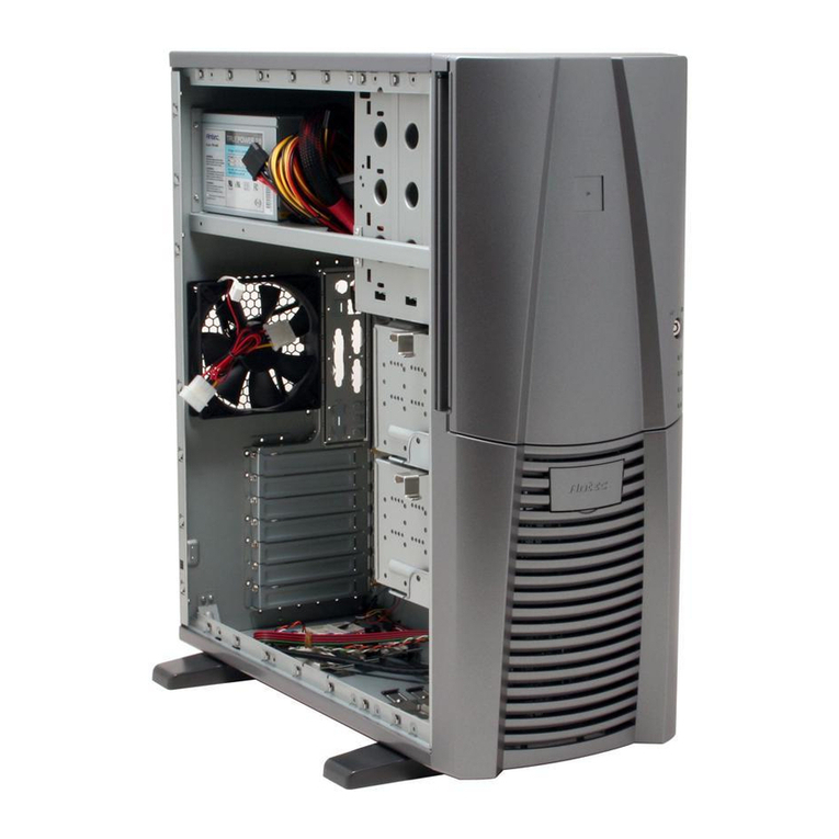
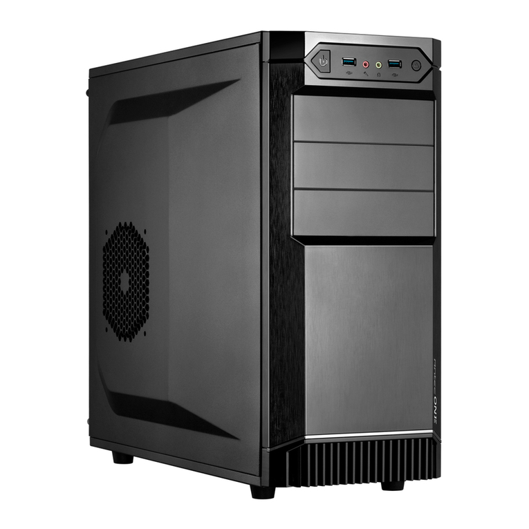
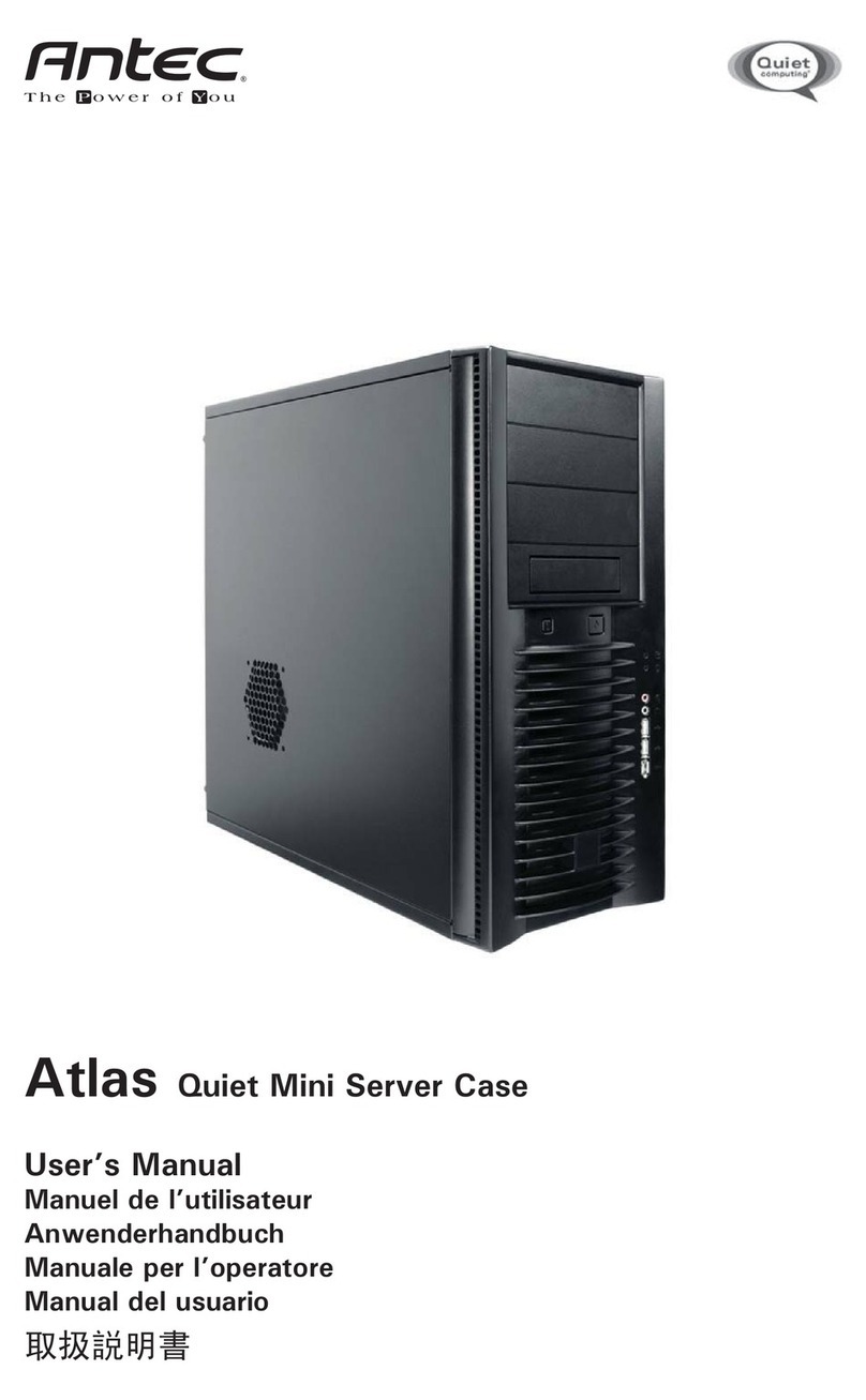
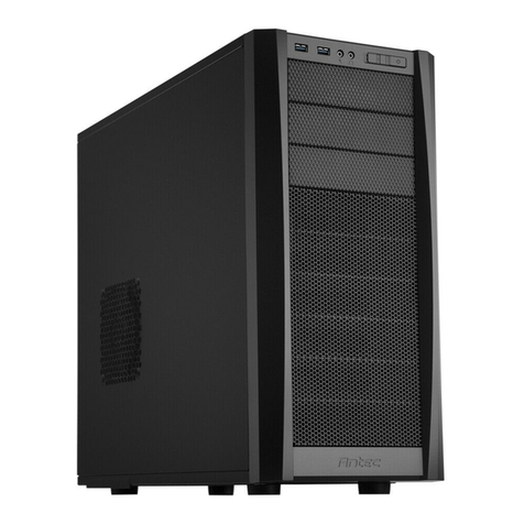
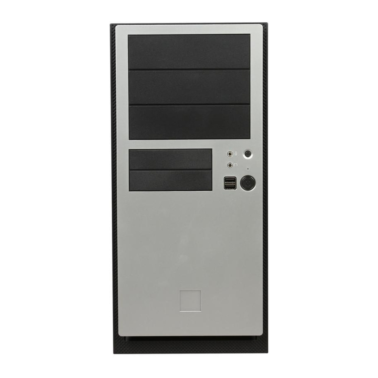
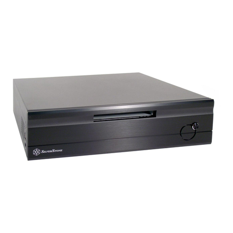
Antec New Solution NSK 3400 User manual

New Solution Series
NSK 3400
User’s Manual
Manuel de l’utilisateur
Anwenderhandbuch
Manuale per l’operatore
Manual del usuario
পᡅ䂀ᯢ

Table of Contents
Table des matières / Inhaltsverzeichnis
Indice / Índice /
• English --------------------------- 1
• Français ------------------------- 7
• Deutsch ----------------------- 14
• Italiano ------------------------- 20
• Español ----------------------- 27
• ------------------------- 34
• Illustration -------------------- 40

1
At Antec, we continually refine and improve our products to ensure the highest
quality. So it’s possible that the new case may differ slightly from the descriptions
in this manual. This isn’t a problem; it’s simply an improvement. As of the date of
publication, all features, descriptions, and illustrations in this manual are correct.
New Solution Series User’s Manual
NSK 3400
Quiet Micro ATX Case
The Power Supply
NSK 3400 comes with a 380 Watt universal input, active PFC, single 80mm fan
cooled power supply which meets the ATX 12V v2.01 specification. It is a high
efficiency power supply that delivers cleaner and environmentally friendlier power
to the system. This includes dual 12V output rails that deliver safer and more
reliable output to the system’s components, as well as higher energy efficiency
which reduces power consumption by up to 25%, saving you money on your
electricity bill. In addition we’ve included a variety of industrial-grade protective
circuitry: OPP (over power protection), OVP (over voltage protection), UVP (under
voltage protection), and SCP (short circuit protection).
This power supply is backwards compatible with previous ATX 12V form factor
power supplies. To make sure you connect the power supply properly, please refer
to the user manuals supplied with the motherboard and peripherals before connect-
ing any of them to the power supply.
The power supply comes with a main power switch. Make sure to turn the switch
to the ON ( I ) position before you boot up the computer for the first time.
Normally, you won’t need to switch to the OFF (O) position, since the power
supply includes a soft on/off feature. This lets you turn the computer on and off
by using the soft switch on the computer case. If the computer crashes and you
can’t shut it down using the soft switch, you can switch the main power to the
OFF (O) position, to clear the fault, then reboot.
This power supply features Power Factor Correction (PFC) circuitry in accordance
with European standard regulation code EN61000-3-2. By altering the input
current wave shape, PFC improves the power factor of the power supply. This
results in increased energy efficiency, reduced heat loss, prolonged life for power
distribution and consumption equipment, and improved output voltage stability.
Together with the high efficiency design and the quiet 80mm fan, the power
supply delivers not only a cleaner but also a quieter operating environment.
Disclaimer
This manual is intended only as a guide for Antec’s Computer Enclosures.
For more comprehensive instructions on installing the motherboard and peripherals,
please refer to the user’s manuals which come with the components and drives.

2
The Dual Chamber Structure
The case is divided into two chambers — the motherboard chamber and the power
supply chamber to separate heat and noise from each section for maximum quiet
and cool operation.
Set Up
1. Take the case out of the box. Remove the biodegradable carton and plastic bag.
2. Place the case upright with the power supply fan at the back facing you on a
stable flat surface.
3. Remove the two thumbscrews fastening to the top cover of the case. These
are the only screws you need to remove to open the case. Set these screws
aside and keep them separate from the other screws.
4. Slide the top panel toward the rear of the case and lift it up.
5. At the top of the each side panel, in front of the power supply, there is a tab.
Using this, lift and pull the side panels out to remove.
6. Inside the case you should see the power supply, some wiring (LED’s, etc.), an
installed I/O panel, a power cord and a plastic bag containing more hardware
(screws, brass standoff, plastic stands, etc.).
Motherboard Installation
This manual is not designed to cover CPU, RAM, or expansion card installation.
Please consult the motherboard manual for specific mounting instructions and
troubleshooting.
1. Lay the case down so that the open side is up. You should be able to see the
drive cage and power supply.
2. Make sure you have the appropriate I/O panel for the motherboard. If the panel
provided is not suitable for the motherboard, please contact the motherboard
manufacturer for the correct I/O panel.
3. Line up the motherboard with the standoff holes, and determine which ones
line up and remember where they are. Not all motherboards will match with all
of the provided screw holes, and this is not necessary for proper functionality.
Some standoffs may be pre-installed for your convenience.
4. Lift up and remove the motherboard.
5. Screw in the brass standoffs to the threaded holes that line up with the
motherboard.
6. Place the motherboard on the brass standoffs.
7. Screw in the motherboard to the standoffs with the provided Phillips-head
screws.
8. The motherboard is now installed.
Connecting the Power and LED
The power supply conforms to the ATX 12V v2.01 standard. Before you connect
the power supply to any of the devices, please consult the appropriate user
manuals for the motherboard and other peripherals.
1. Connect the 24-pin Main Power Connector and the
4-pin to the motherboard as needed. If the moth-
erboard uses a 20-pin connector; detach the 4-pin
attachment on the 24-pin power
connector (see pictures 1 and 2).
Picture 1 Picture 2
For 24-pin
motherboards
For 20-pin
motherboards

3
2. Connect the Reset switch (labeled RESET SW) to the motherboard at the RST
connector. Make sure the label always faces the front of the case.
3. Power LED (labeled POWER LED) connector is located behind the Reset
connector.
4. Power Switch (labeled POWER SW) connects to the PWR connector on the
motherboard.
5. Hard Drive LED (labeled H.D.D. LED) connects to the IDE connector.
USB Connection
You will find a single 10-pin connector on a cable attached to the front USB ports.
This is an Intel standard connector, which is keyed so that it can’t be accidentally,
reversed as long as it is connected to a proper Intel standard motherboard header.
Connect the 10-pin connector to the motherboard headers so that the blocked pin
fits over the missing header pin.
Note: Please check the motherboard manual for the USB header pin layout and
make sure it matches the attached table. If it does not match this Intel standard,
please call Antec customer support at (800) 22ANTEC (North America) or at
+31 (0) 10 462-2060 (Europe) to buy a USB adapter. This adapter will allow you
to connect the front USB to the motherboard on a pin-by-pin basis.
Motherboard Pin Layout
Connecting the IEEE 1394 (FireWire®, i.Link®) Port
You will find a single 10-pin connector on a cable attached to the front IEEE 1394
connection. This is an Intel standard connector, which is keyed so that it can’t be
accidentally reversed as long as it is connected to a proper Intel standard
motherboard header. Connect the 10-pin connector to the motherboard header so
that the blocked pin fits over the missing header pin.
Note: Please check the motherboard manual for the IEEE 1394 header pin layout
and make sure it matches the attached table. If you intend to connect the front
FireWire® port to an IEEE 1394 add-on card that comes with an external-type IEEE
1394 connector, please call Antec customer service at (800) 22ANTEC
(North America) or +31 (0) 10 462-2060 (Europe) to buy an adapter. This adapter
will allow you to connect the front IEEE 1394 port to the external-type connector.
Pin Signal Names Pin Signal Names
1USB Power 1 2USB Power 2
3Negative Signal 1 4Negative Signal 2
5Positive Signal 1 6Positive Signal 2
7Ground 1 8Ground 2
9Key (No Connection) 10 Empty Pin
12
109

4
Pin Assignment for Front Panel IEEE 1394 Connector
Connecting the Audio Ports
There is an Intel standard 10-pin connector (with 7 individual wires with
connectors) coming out from the front panel speaker and microphone connection.
If the motherboard supports Intel’s standard onboard audio connector, you can
plug in the 10-pin connector directly onto the board. For non-Intel standard audio
connection, you need to plug the 7 individual connectors to the motherboard.
See instruction below:
Locate the internal audio connectors from the motherboard or sound card.
Consult the motherboard or sound card manual for the pin-out positions.
1. Microphone Signal Pin: Connect the MIC connector to this pin.
2. Microphone Power: Connect the MIC-BIAS connector to this pin.
3. Ground Pin: Connect the AUD GND connector to this pin.
4. Front Right Speaker Out Pin: Connect the FPOUT-R connector to this pin.
5. Front Left Speaker Out Pin: Connect the FPOUT-L connector to this pin.
6. Rear Right Speaker Out Pin: Connect the RET-R connector to this pin.
7. Rear Left Speaker Out Pin: Connect RET-L connector to this pin.
3.5” Device Installation
There is one external 3.5” drive bay under the 5.25” drive bay.
1. Carefully remove the 3.5” drive bay cover from the bezel. Load the drives from
the front, lining them up to the front of the drive cage.
2. With one hand supporting the drive, fasten the drive with the screws provided.
3. Find a small 4-pin connector on the power supply and connect it to the male
4-pin connector on the floppy drive.
There are two internal 3.5” drive bays for the hard disk. One is inside the lower
5.25” drive bay and the other is at the bottom of the case. Both use a HDD tray
with soft silicone grommets to mount the HDD.
1. Remove the screw fastening the HDD tray to the case and slide the tray out of
the case.
2. Mount the hard drive into the drive tray through the bottom silicone grommets
with the special screws provided. Note: Don’t over-tighten the screws.
Over-tightening the screws will reduce the vibration and noise-dampening
ability of the silicone grommets.
3. Slide and fasten the tray back into the case.
4. Repeat the same procedure for the other as necessary.
Pin Signal Names Pin Signal Names
1 TPA+ 2 TPA–
3 Ground 4 Ground
5 TPB+ 6 TPB–
7 +12V (Fused) 8 +12V (Fused)
9 Key (No Pin) 10 Ground
12
109

5
Note: We recommend using the lower drive tray (the one at the bottom of the case
) as it will provide better cooling and cable management. Using the HDD bay at the
bottom of the case may result in being unable to use the 4th PCI slot depending
on the length of the card used.
5. Find a 4-pin Molex connector on the power supply and connect it to the male
4-pin connector on the device.
5.25” Device Installation
There are two external 5.25” drive bays (with one HDD tray inside the lower
5.25” bay). Note: If you choose to use the lower drive bay for the HDD, you can
only install one 5.25” device to the case.
1. Looking from the rear of the case you can see some metal grilles covering the
5.25” drive bays. Carefully push a screwdriver through the metal grille and
gently push the plastic drive bay cover outwards until it comes off.
2. Use your hands to twist the metal plate back and forth until it breaks off.
Be careful of the newly exposed metal where the grille was attached, as these
areas are likely to be sharp. Note: Don’t break off the metal grilles covering the
drive bays that you are not using now
3. Slide the 5.25” device into the bay from the front.
4. Fasten the 5.25” device into the drive bay with screws provided.
5. Repeat the same procedure for other devices.
6. Connect a 4-pin large white connector from the power supply to the male 4-pin
connector on each of the devices.
Cooling System
The Rear Exhaust TriCool™ fan:
The NSK 3400 comes with one 120mm TriCool™ fan preinstalled. This fan has a
three-speed switch that lets you choose between quiet, performance, or maximum
cooling. (See specifications below.) The fan is installed so that the air is blowing
out of the case. Connect a large 4-pin connector from the power supply to the
male 4-pin connector on the fan. Note: The default setting of the fan is Low. We
recommend this speed to maximize quiet computing.
Note regarding fan speed controllers: The minimum voltage to start the fan is 5V.
We recommend setting the fan speed to High if the fan will be connected to a fan
control device or to the Fan-Only connector found on some of Antec’s power
supplies. A fan-control device regulates the fan speed by varying the voltage to it.
The voltage may start as low as 4.5V to 5V. Connecting a TriCool™ set on
Medium or Low to a fan-control device may result in the fan not being able to
start. The already lowered voltage from the fan control device will be further
reduced by the TriCool™ circuitry below 5V.

6
Specifications:
Size: 120 x 120 x 25.4mm
Rated Voltage: DC 12V
Operating Voltage: 10.2V ~ 13.8V
The Front 92mm Fans
This case comes with two optional 92mm fan mounts in the front of the case.
The front fan should be installed so that the air is blowing into the case from the
front. We recommend using Antec TriCool™ 92mm fans and setting the speed to
LOW.
1. There are four special fan screws in the toolbox. Use these to fasten the fan to
the case from the inside.
2. Connect the fan to the power supply or onto the motherboard.
Speed Input
Current
Air Flow Static
Pressure
Acoustical
Noise
Input
Power
High
2000 RPM
0.24A
(Max.)
2.24 m³ / min
(79 CFM)
2.54 mm-H2O
(0.10 inch-H2O)
30 dBA 2.9 W
Medium
1600 RPM
0.2A 1.59 m³ / min
(56 CFM)
1.53 mm-H2O
(0.06 inch-H2O)
28 dBA 2.4 W
Low
1200 RPM
0.13A 1.1 m³ / min
(39 CFM)
0.92 mm-H2O
(0.04 inch-H2O)
25 dBA 1.6 W

7
Chez Antec, nous améliorons constamment nos produits pour garantir la plus
haute qualité. Il est donc possible que votre nouveau boîtier diffère légèrement des
descriptions fournies dans ce manuel. Ceci n’est pas un problème, seulement une
amélioration. A la mise sous presse, toutes les caractéristiques, descriptions et
illustrations de ce manuel sont correctes.
Guide de l’utilisateur de la nouvelle série Solution
NSK 3400
Boîtier Micro ATX silencieux
Bloc d’alimentation
Le NSK 3400 est fourni un un bloc d’alimentation avec correction du facteur de
puissance (PFC) active à entrée universelle 380 W refroidi par un ventilateur de
80mm conforme aux spécifications ATX 12V v2.01. C’est un bloc d’alimentation
à haut rendement énergétique qui délivre une alimentation plus propre et plus
respectueuse de l’environnement au système. Il inclut des rails de sortie 12V
double qui délivrent une alimentation plus sûre et fiable aux composants du
système, de même qu’un rendement énergétique supérieur, ce qui peut réduire
la consommation d’électricité de 25% et vous faire économiser de l’argent sur
vos quittances d’électricité. En outre, nous avons inclus une variété de circuits de
protection de niveau industriel : OPP (protection contre les surpuissances), OVP
(protection contre les surtensions) UVP (protection contre les baisses de tension)
et SCP (protection par court-circuit).
Ce bloc d’alimentation est rétro-compatible avec les précédents blocs
d’alimentation de facteur de forme ATX 12V. Pour être sûr de connecter correcte-
ment votre bloc d’alimentation, veuillez consulter les manuels d’utilisation fournis
avec votre carte mère et vos périphériques avant de brancher l’un d’entre eux sur
le bloc d’alimentation.
Ce bloc d’alimentation inclut un interrupteur d’alimentation général. Assurez-vous
de mettre l’interrupteur en position ON (I) avant de démarrer votre ordinateur pour
la première fois. En règle générale, il n’est pas nécessaire de mettre l’interrupteur
en position OFF (O), car le bloc d’alimentation est muni d’un dispositif de marche/
arrêt logiciel qui allume et éteint votre ordinateur au moyen d’un interrupteur situé
sur le boîtier de l’ordinateur. Si votre ordinateur plante et que vous ne pouvez pas
l’arrêter via l’interrupteur logiciel, vous pouvez mettre l’interrupteur d’alimentation
en position OFF (O) pour éliminer l’erreur, puis réinitialiser.
Ce bloc d’alimentation inclut un circuit de correction du facteur de puissance (PFC)
conforme au code de réglementation des normes européennes EN61000-3-2. En
modifiant la courbe d’entrée de courant, la fonction PFC améliore le facteur de
Avis de non-responsabilité
Ce manuel sert uniquement de guide à l’utilisation des boîtiers d’ordinateur
Antec. Pour des instructions détaillées sur l’installation de la carte mère et des
périphériques,consultez les guides d’utilisateur accompagnant ces composants
et lecteurs.

8
puissance de l’alimentation. Ceci se traduit par une hausse du rendement
énergétique, une baisse de la perte calorifique, une plus longue durée de vie pour
le matériel de distribution et de consommation d’alimentation et une plus grande
stabilité de la tension de sortie. Grâce à son haut rendement énergétique et son
ventilateur de 80mm silencieux, le bloc d’alimentation donne un environnement
non seulement plus propre, mais aussi plus silencieux.
Structure à deux compartiments
Ce boîtier a deux compartiments — le compartiment de la carte mère et le
compartiment du bloc d’alimentation pour isoler bruit et chaleur de chaque
compartiment et produire un fonctionnement frais et silencieux au maximum.
Installation
1. Retirez le boîtier de son emballage. Ôtez la mousse de la cartouche et le sac en
plastique.
2. Placez le boîtier à la verticale avec le ventilateur du bloc d’alimentation à
l’arrière tourné vers vous sur une surface plate stable.
3. Retirez les deux vis à oreilles qui fixent le capot supérieur du boîtier. Ce sont
les seules vis qui doivent être retirées pour ouvrir le boîtier. Mettez ces vis de
côté et maintenez-les à l’écart des autres vis.
4. Glissez le panneau supérieur vers l’arrière du boîtier et soulevez-le.
5. En haut de chaque panneau latéral, devant le bloc d’alimentation, se trouve une
patte. Soulevez cette patte et tirez les panneaux latéraux vers l’extérieur pour
les retirer.
6. A l’intérieur du boîtier, vous trouverez le bloc d’alimentation, des câbles
(voyants, etc.), un panneau E/S installé, un cordon d’alimentation et un sachet
en plastique contenant de la quincaillerie supplémentaire (vis, entretoise en
laiton, supports en plastique, etc.).
Installation de la carte mère
Ce manuel n’aborde pas l’installation de l’UC, de la mémoire vive ni de la carte
d’extension. Pour des instructions de montage et de dépannage détaillées,
consultez le manuel accompagnant la carte mère.
1. Couchez le boîtier en tournant le côté ouvert vers le haut. Vous devriez pouvoir
voir le panier de lecteurs et le bloc d’alimentation.
2. Assurez-vous que le panneau E/S est adapté à la carte mère. Si le panneau
fourni n’est pas adapté à votre carte mère, contactez le fabricant de la carte
mère pour vous procurer le panneau E/S adéquat.
3. Alignez la carte mère sur les trous des espaceurs, déterminez lesquels sont
alignés et mémorisez leur emplacement. Les cartes mères ne correspondent pas
toutes aux trous de vis fournis ; ceci est normal et sera sans conséquence sur
la fonctionnalité. Il est possible que des espaceurs soient préinstallés pour une
plus grande commodité.
4. Soulevez et retirez la carte mère.
5. Vissez les espaceurs en laiton aux trous taraudés qui s’alignent avec la carte
mère.
6. Placez la carte mère sur les espaceurs en laiton.
7. Vissez la carte mère aux espaceurs avec les vis cruciformes fournies.
8. La carte mère est à présent installée.
9
Raccordement des prises d’alimentation/voyants DEL
Le bloc d’alimentation est conforme au standard ATX 12V v2.01. Avant de
brancher le bloc d’alimentation sur l’un de vos périphériques, consultez les manu-
els d’utilisation appropriés pour votre carte mère et autres périphériques.
1. Branchez le connecteur d’alimentation secteur à 24
broches et le connecteur à 4, au besoin, sur votre carte
mère. Si votre carte mère utilise un connecteur à 20
broches, détachez l’accessoire à 4 broches du con-
necteur d’alimentation à 24 broches
(cf. figures 1 et 2).
2. Branchez l’interrupteur de réinitialisation (libellé RESET
SW) sur la carte mère via le connecteur RST. Veillez à
ce que l’étiquette soit toujours face à l’avant du boîtier.
3. Le connecteur du voyant d’alimentation (libellé POWER LED) se situe derrière le
connecteur de réinitialisation.
4. L’interrupteur de tension (libellé POWER SW) se branche sur le connecteur
PWR de la carte mère.
5. Le voyant du disque dur (libellé H.D.D LED) se branche sur le connecteur IDE.
Connexion USB
Vous trouverez un connecteur simple à 10 broches sur un câble fixé aux ports
USB avant. Il s’agit d’un connecteur Intel standard, possèdant un détrompeur pour
empêcher son inversion accidentelle, à condition qu’il soit raccordé à une barrette
de contact de carte mère Intel standard. Branchez le connecteur à 10 broches
sur les barrettes de contact de la carte mère afin que la broche avec détrompeur
s’ajuste correctement à la broche de barrette de contact manquante.
Remarque : Consultez le guide de la carte mère pour connaître la disposition des
broches de barrette de contact USB et assurez-vous qu’elle correspond au tableau
ci-joint. Si elle ne satisfait pas à cette norme Intel, contactez le service clientèle
d’Antec au (800) 22ANTEC (Amérique du Nord) ou au
+31 (0) 10 462-2060 (Europe) pour acheter un adaptateur USB. Cet adaptateur
vous permettra de brancher, broche par broche, le port avant USB à la carte mère.
Disposition des broches de la carte mère
Pour cartes
mères à 24
broches
Pour cartes
mères à 20
broches
Figure 1 Figure 2
Broche Nom du signal Broche Nom du signal
1Alimentation USB 1 2Alimentation USB 2
3Signal négatif 1 4Signal négatif 2
5Signal positif 1 6Signal positif 2
7Masse 1 8Masse 2
9Détrompeur (aucun
contact)
10 Broche vide
12
109

10
Branchement du port IEEE 1394 (FireWire®, i.Link®)
Vous trouverez un connecteur simple à 10 broches sur un câble fixé au raccord
avant IEEE 1394. Il s’agit d’un connecteur Intel standard, possédant un dé-
trompeur pour empêcher son inversion accidentelle, à condition qu’il soit raccordé
à une barrette de contact de carte mère Intel standard adéquate. Branchez le
connecteur à 10 broches sur la barrette de contact de la carte mère afin que la
broche avec détrompeur s’ajuste correctement à la broche de barrette de contact
manquante.
Remarque : Consultez le guide de la carte mère pour connaître la disposition des
broches de barrette de contact IEEE 1394 et assurez-vous qu’elle correspond
au tableau ci-joint. Si vous envisagez de brancher le port avant FireWire® sur
une carte externe IEEE 1394 munie d’un connecteur IEEE 1394 de type externe,
contactez le service clientèle d’Antec aux numéros de téléphone suivants : (800)
22ANTEC (Amérique du Nord) ou +31 (0) 10 462-2060 (Europe) pour acheter un
adaptateur. Cet adaptateur vous permettra de brancher le port avant IEEE 1394 au
connecteur de type externe.
Affectation des broches pour le connecteur IEEE 1394 du panneau avant
Branchement des ports audio
Un connecteur standard 10 broches Intel (doté de 7 fils individuels munis de
connecteurs) est issu d’un connecteur de haut-parleur avant et de microphone.
Si votre carte mère prend en charge le connecteur audio intégré standard d’Intel,
vous pouvez brancher le connecteur 10 broches directement à la carte. Pour une
connexion audio standard d’un autre fabricant, vous devez brancher les 7
connecteurs individuels à la carte mère. Voir les instructions ci-dessous :
Localisez les connecteurs audio internes de votre carte mère ou carte son.
Consultez les positions des broches dans le manuel de votre carte mère ou de
votre carte son.
1. Broche de signal du microphone : raccordez le connecteur MIC à cette broche.
2. Alimentation du microphone : raccordez le connecteur MIC-BIAS à cette
broche.
3. Broche de terre : raccordez le connecteur AUD GND à cette broche.
4. Broche de sortie du haut-parleur avant droit : raccordez le connecteur FPOUT-R
à cette broche.
5. Broche de sortie du haut-parleur avant gauche : Branchez le connecteur
FPOUT-L sur cette broche.
Broche Nom du signal Broche Nom du signal
1 TPA+ 2 TPA–
3 Masse 4 Masse
5 TPB+ 6 TPB–
7 +12V (à fusibles) 8 +12V (à fusibles)
9 Verrou (aucune
broche)
10 Masse
12
109

11
6. Broche de sortie du haut-parleur arrière droit : Branchez le connecteur RET-R
sur cette broche.
7. Broche de sortie du haut-parleur arrière gauche : Branchez le connecteur RET-L
sur cette broche.
Installation d’un périphérique de 3,5 pouces
Une baie de lecteur externe de 3,5 pouces se trouve juste en dessous de la baie de
5,25 pouces.
1. Retirez avec précaution la baie de lecteur de 3,5 pouces de la collerette
d’encastrement. Installez les lecteurs par l’avant, en les alignant sur l’avant du
panier de lecteurs.
2. En soutenant le lecteur d’une main, fixez le panier avec les vis fournies.
3. Branchez un petit connecteur à 4 broches du bloc d’alimentation sur le con-
necteur mâle à 4 broches du lecteur de disquette.
Il existe deux baies de lecteur internes de 3,5 pouces pour disques durs. L’une se
trouve à l’intérieur de la baie de lecteur de 5,25 pouces inférieure et l’autre en bas
du boîtier. Les deux utilisent un plateau de disque dur comportant des œillets en
silicone molle pour l’installation du disque dur.
1. Retirez la vis qui fixe le plateau de disque dur sur le boîtier et sortez le plateau
du boîtier.
2. Installez l’unité de disque dur dans le plateau en enfilant les vis spéciales
fournies à travers les œillets en caoutchouc. Remarque : Ne serrez pas trop les
vis Le serrage excessif des vis diminuera la capacité de réduction des vibrations
et du bruit des œillets en silicone.
3. Glissez et fixez à nouveau le plateau dans le boîtier.
4. Répétez la procédure pour l’autre, si nécessaire.
Remarque : Nous vous recommandons d’utiliser le plateau de disque dur
inférieure (celui qui est en bas du boîtier) dans la mesure où il fournira un
refroidissement supérieur et une meilleure gestion des câbles. L’utilisation de
la baie de disque dur en bas du boîtier risque de se solder par l’impossibilité
d’utilisation du 4ème logement PCI, selon la longueur de la carte utilisée.
5. Trouvez un connecteur Molex 4 broches sur le bloc d’alimentation et
branchez-le sur le connecteur mâle 4 broches du périphérique.
Installation d’un périphérique de 5,25 pouces
Vous trouverez deux baies de lecteur de 5,25 pouces externes (avec un plateau de
disque dur dans la baie de 5,25 pouces inférieure). Remarque : Si vous choisissez
d’utiliser la baie de lecteur inférieure pour le disque dur, vous ne pourrez installer
qu’un seul lecteur de 5,25 pouces dans le boîtier.
1. En regardant par l’arrière du boîtier, vous pouvez voir des grilles métalliques sur
les baies de lecteur de 5,25 pouces. Insérez doucement un tournevis à travers
la grille métallique et poussez avec précaution le couvercle en plastique de la
baie jusqu’à ce qu’il se dégage.
2. Servez-vous de vos mains pour imprimer un mouvement de va-et-vient à la
plaque métallique jusqu’à ce qu’elle se détache. Faites attention au métal qui
sera exposé, à l’endroit où la grille était attachée, dans la mesure où ces zones
seront probablement coupantes. Remarque : Ne détachez pas les grilles
métalliques qui recouvrent les baies que vous n’envisagez pas d’utiliser tout de
suite.
3. Glissez le périphérique de 5,25 pouces dans la baie, par l’avant.

12
4. A l’aide des vis fournies, fixez votre unité de 5,25 pouces dans la baie d’unité.
5. Reprenez la procédure pour les autres périphériques.
6. Branchez un grand connecteur blanc à 4 broches du bloc d’alimentation sur le
connecteur mâle à 4 broches de chacun des périphériques.
Système de refroidissement
Le ventilateur d’évacuation arrière TriCool™
Le NSK 3400 est fourni avec un ventilateur TriCool™ de 120mm préinstallé.
Ce ventilateur comporte un interrupteur à trois vitesses vous permettant de choisir
entre un refroidissement silencieux, performant ou maximal (Reportez-vous aux
spécifications ci-dessous.) Le ventilateur est installé de manière que l’air soit
évacué hors du boîtier. Branchez un gros connecteur à 4 broches du bloc
d’alimentation sur le connecteur mâle à 4 broches du ventilateur.
Remarque : Par défaut, le ventilateur est réglé sur basse vitesse. Nous vous
recommandons cette vitesse pour un fonctionnement silencieux maximum.
Remarque au sujet des régulateurs de vitesse des ventilateurs :
La tension minimale pour démarrer le ventilateur est de 5 V. Nous vous
recommandons l’utilisation du réglage High (vitesse élevée) si le ventilateur est
branché sur un dispositif de commande de ventilateur ou sur le connecteur
« Fan-Only », rencontré sur certains blocs d’alimentation Antec. Un dispositif de
commande du ventilateur régule la vitesse du ventilateur en variant la tension
qui l’alimente. La tension peut démarrer à un niveau aussi faible que 4,5-5V. Le
branchement d’un ventilateur TriCool™ réglé à une vitesse moyenne ou faible sur
un dispositif de commande de ventilateur peut empêcher le ventilateur de
démarrer. La tension déjà faible du dispositif de commande sera davantage réduite
par le circuit du TriCool™ en dessous de 5V.
Caractéristiques techniques :
Dimensions : 120 x 120 x 25.4mm
Tension nominale : Courant continu 12V
Tension de fonctionnement : 10,2V ~ 13,8V
Vitesse Courant
d’entrée
Circulation
d’air
Pression
statique
Niveau
acoustique
Puissance
d’entrée
Elevée
2000
tr/min.
0,24A
(Max.)
2,24 m³
/ min (79
CFM)
2,54 mm de
H2O(0,10
pouce de H2O)
30 dBA 2,9 W
Moyenne
1600
tr/min.
0,2A 1,59 m³
/ min (56
CFM)
1,53 mm de
H2O(0,06
pouce de H2O)
28 dBA 2,4 W
Basse
1200
tr/min.
0,13A 1,1 m³ / min
(39 CFM)
0,92 mm de
H2O(0,04
pouce de H2O)
25 dBA 1,6 W

13
Ventilateurs avant de 92mm
Ce boîtier est fourni avec deux montants de ventilateur 92mm en option sur
l’avant du boîtier. Le ventilateur avant doit être installé de sorte à ce que l’air soit
expulsé par l’avant. Nous vous recommandons d’utiliser des ventilateurs Antec
TriCool™ de 92mm et de sélectionner le réglage basse vitesse.
1. Vous trouverez quatre vis de ventilateur spéciales dans le sachet de visserie.
Utilisez ces vis pour fixer le ventilateur au boîtier par l’intérieur.
2. Branchez le ventilateur sur le bloc d’alimentation ou sur la carte mère.

14
Die hohe Qualität der Produkte von Antec wird durch ständige Optimierung und
Weiterentwicklung sichergestellt. Daher ist es möglich, dass Ihr neues Gehäuse
in einigen Details nicht genau mit den Beschreibungen in dieser Bedienungsanlei-
tung übereinstimmt. Dabei handelt es sich nicht um ein Problem, sondern vielmehr
um eine Verbesserung. Alle in dieser Bedienungsanleitung genannten technischen
Leistungsmerkmale, Beschreibungen und Abbildungen sind zum Zeitpunkt der
Veröffentlichung korrekt.
Benutzerhandbuch für die neue Solution Serie
NSK 3400
Leises Micro ATX Gehäuse
Das Netzteil
Das NSK 3400, das der neuesten ATX 12V v2.01 Spezifikation entspricht, ist
mit einem 380 Watt starken Netzteil mit Universaleingang sowie einem einzelnen
80ºmm Lüfter mit Active PFC Kühlung ausgestattet. Dieses Netzteil bietet höchste
Leistung für einen noch umweltfreundlicheren Betrieb. Darin eingeschlossen zwei
+12V-Ausgangsschienen, die eine sicherere und zuverlässigere Stromversorgung
der Systemkomponenten gewährleisten. Dies ermöglicht eine Senkung des
Stromverbrauchs um bis zu 25 %, was sich positiv auf der Stromrechnung
bemerkbar macht. Dazu kommt eine Reihe von Schutzschaltkreisen in
Industriequalität: OPP (Over Power Protection - Überlastungsschutz), UVP (Under
Voltage Protection - Unterspannungsschutz) und SCP (Short Circuit Protection
- Schutz vor Kurzschlüssen).
Dieses Netzteil ist mit den älteren ATX 12V Formfaktor Netzteilen abwärts kom-
patibel. Um eine korrekte Installation zu gewährleisten, lesen Sie vor dem An-
schließen des Netzteils an ihre Geräte die Benutzerhandbücher für Motherboard
und Peripheriegeräte durch.
Dieses Netzteil verfügt über einen Hauptnetzschalter. Bringen Sie diesen bitte in
die Stellung ON (I), bevor Sie den PC zum ersten Mal booten. In der Regel muss er
nicht ausgeschaltet werden (OFF - O), da das Netzteil über einen Softschalter zum
Ein- und Ausschalten verfügt. Dies bedeutet, dass Sie Ihren PC über die Softtaste
des PC-Gehäuses ein- und ausschalten können. Wenn der PC abstürzt und Sie ihn
nicht über die Softtaste ausschalten können, bringen Sie den Netzschalter in die
Position OFF (0) und führen Sie einen Neustart durch.
Dieses Netzteil verfügt gemäß der Europäischen Norm EN61000-3-2 über
Schaltkreise für eine so genannte Blindstromkompensation (Power Factor
Correction), bei der durch eine Änderung der Eingangswellenform der
Leistungsfaktor des Netzteils und die Energieeffizienz erhöht, der Wärmeverlust
gemindert, die Lebensdauer von Stromverteilung und Verbrauchskomponenten
Haftungsausschluss
Dieses Handbuch dient ausschließlich als Anleitung für PC-Gehäuse von Antec.
Genauere Anleitungen zur Installation des Motherboards und anderer Geräte
finden Sie in den Benutzerhandbüchern dieser Komponenten und Laufwerke.

15
sowie die Stabilität der Ausgangsspannung verbessert werden. Zusammen mit dem
höchst effizienten Design und dem kaum hörbaren 80mm Lüfter bietet das Netzteil
nicht nur eine umweltfreundlichere, sondern auch eine extrem leise
Betriebsumgebung.
Das Doppelkammersystem
Das Gehäuse ist in zwei Kammern für Motherboard und Netzteil unterteilt, die
sie gegen Hitze und Geräusche isolieren und so einen kühlen und leisen Betrieb
ermöglichen.
Vorbereitung & Installation
1. Nehmen Sie das Gehäuse aus der Verpackung. Entfernen Sie Pappschachtel
und Plastikhülle.
2. Platzieren Sie es aufrecht auf einer ebenen Oberfläche, so dass die Rückseite
mit dem Netzteillüfter zu Ihnen zeigt.
3. Lösen Sie die beiden Rändelschrauben, mit denen die obere Abdeckung am
Gehäuse befestigt ist. Dies sind die einzigen Schrauben, die Sie lösen müssen,
um an das Gehäuseinnere zu gelangen. Legen Sie die Schrauben beiseite und
achten Sie darauf, sie nicht mit den anderen zu verwechseln.
4. Schieben Sie die obere Abdeckung nach hinten und heben Sie sie nach oben ab.
5. An jeder der seitlichen Abdeckungen befindet sich oben in Höhe des Netzteils
eine Plastikzunge. Ziehen Sie an diesen, um die Abdeckungen herauszuheben.
6. Im Inneren des Gehäuses sollten sich das Netzteil, verschiedene Kabel (LEDs
etc.), eine installierte E/A-Platine, ein Netzkabel und eine Plastiktüte mit weit-
erer Hardware (Schrauben, Messing-Abstandshalter, Plastikfüße etc.) befinden.
Installation des Motherboards
Die Installation von CPU, RAM-Speicher oder Erweiterungskarten wird in diesem
Handbuch nicht beschrieben. Anweisungen zum Einbau und zur Fehlersuche finden
Sie im Handbuch Ihres Motherboards.
1. Legen Sie das Gehäuse so, dass die offene Seite nach oben weist.
Laufwerkkäfig und Netzteil sollten zu sehen sein.
2. Vergewissern Sie sich, dass Sie die richtige E/A-Platine für Ihr Motherboard
haben. Falls nicht, wenden Sie sich zwecks Bestellung der korrekten Platine an
den Motherboard-Hersteller.
3. Richten Sie Ihr Motherboard mit den Abstandslöchern aus und merken Sie sich
die Anordnung. Nicht alle Motherboards passen zu allen vorhandenen Löchern.
Dies stellt allerdings kein Problem dar und beeinträchtigt auch nicht die
Funktionstüchtigkeit. Es ist möglich, dass manche Abstandshalter bereits
vorinstalliert sind.
4. Heben Sie das Motherboard aus dem Gehäuse.
5. Schrauben Sie die Messing-Abstandshalter in die Gewindelöcher, die mit dem
Motherboard ausgerichtet sind.
6. Setzen Sie Ihr Motherboard auf die Messingabstandshalter auf.
7. Befestigen Sie es mit den mitgelieferten Kreuzschlitzschrauben an den
Abstandshaltern.
8. Damit ist Ihr Motherboard installiert.

16
Anschluss von Stromversorgung und LED
Das Netzteil entspricht dem ATX 12V v2.01 Standard. Bevor Sie das Netzteil an
eines der anderen Geräte anschließen, konsultieren Sie die entsprechenden
Handbücher für Motherboard und andere Peripheriegeräte.
1. Verbinden Sie ggf. den 24-poligen
Hauptstromanschluss und den 4+12V Anschluss
mit Ihrem Motherboard. Wenn Ihr Motherboard
über einen 20-poligen Anschluss verfügt, nehmen
Sie den 4-poligen Aufsatz vom 24-poligen
Stromanschluss ab (siehe Abb 1 und 2).
2. Schließen Sie den Reset-Schalter (mit RESET SW
gekennzeichnet) an den RST-Stecker Ihres Motherboards an. Bitte sicherstellen,
dass das Etikett stirnseitig zur Gehäusevorderseite weist.
3. Der LED-Stecker (mit POWER LED gekennzeichnet) befindet sich hinter dem
Reset-Stecker.
4. Der Netzschalter (mit POWER SW gekennzeichnet) wird an den PWR-Anschluss
des Motherboards angeschlossen.
5. Die Festplatten-LED (mit H.D.D. LED gekennzeichnet) wird an den IDE-Stecker
angeschlossen.
USB-Anschluss
An einem der Kabel der vorderen USB-Anschlüsse befindet sich ein einzelner
10-poliger Stecker. Dies ist ein Intel-Standardstecker, der getastet ist, damit er
nicht versehentlich umgeschaltet werden kann, solange er an einen
standardgemäßen Intel-Motherboard-Header angeschlossen ist. Verbinden Sie den
10-poligen Stecker mit den Motherboard-Headern, so dass der blockierte Pin auf
den fehlenden Header-Pin passt.
Hinweis: Bitte überprüfen Sie die USB-Header-Pinbelegung im Handbuch Ihres
Motherboards und vergewissern Sie sich, dass sie mit der Tabelle unten
übereinstimmt. Wenn diese nicht dem Intel-Standard entspricht, fordern Sie beim
Antec Kundendienst unter (800) 22ANTEC (Nordamerika) oder unter
+31 (0) 10.462-2060 (Europa) einen USB-Adapter an. Mit diesem Adapter können
Sie den vorderen USB-Anschluss Pin für Pin mit Ihrem Motherboard verbinden.
Pinbelegung des Motherboards
Für Motheboards
mit 24-Poligen
Für Motheboards
mit 20-Poligen
Abb 1 Abb 2
Pin Signalbezeichnungen Pin Signalbezeichnungen
1USB Strom 1 2USB Strom 2
3Negatives Signal 1 4Negatives Signal 2
5Positives Signal 1 6Positives Signal 2
7Masse 1 8Masse 2
9Fest (Kein Pin) 10 Unbelegter Pin
12
109

17
Anschluss des IEEE 1394 (FireWire®, i.Link®) Ports
An einem Kabel des vorderen IEEE 1394-Anschlusses befindet sich ein
einzelner 10-poliger Stecker. Dies ist ein Intel-Standardstecker, der getastet ist,
damit er nicht versehentlich umgeschaltet werden kann, solange er an einen
standardgemäßen Intel-Motherboard-Header angeschlossen ist. Verbinden Sie den
10-poligen Stecker mit dem Motherboard-Header, so dass der blockierte Pin über
den fehlenden Header-Pin passt.
Hinweis: Bitte überprüfen Sie die IEEE 1394-Header-Pinbelegung im Handbuch
Ihres Motherboards und vergewissern Sie sich, dass sie mit der Tabelle unten
übereinstimmt. Wenn Sie beabsichtigen, den vorderen FireWire®-Port an eine mit
einem externen IEEE 1394-Stecker ausgestattete IEEE 1394-Zusatzkarte
anzuschließen, fordern Sie bitte beim Antec-Kundendienst (800) 22ANTEC
(Nordamerika) oder +31 (0) 10.462-2060 (Europa) einen Adapter an. Mit diesem
Adapter können Sie den vorderen IEEE 1394-Port an den externen Stecker
anschließen.
Pinbelegung für vorderen IEEE 1394-Stecker
Anschluss der Audio-Ports
Am vorderen Lautsprecher- und Mikrofonanschluss befindet sich ein 10-poliger
Intel-Standardstecker (7 einzelne Drähte mit Steckverbindungen). Wenn Ihr
Motherboard den Onboard-Audiostecker nach Intel-Standard unterstützt, können
Sie den 10-poligen Stecker direkt ans Board anschließen. Für andere als
Intel-Standardanschlüsse müssen die 7 einzelnen Steckverbindungen am
Motherboard angebracht werden. Siehe dazu folgende Anleitung:
Suchen Sie die internen Audiosteckverbindungen Ihres Motherboards oder Ihrer
Soundkarte. Sehen Sie die Pinanordnung bitte im Handbuch Ihres Motherboards
oder Ihrer Soundkarte nach.
1. Mikrofon-Signalpin: Den MIC-Stecker an diesen Pin anschließen.
2. Mikrofon-Netzstrom: Den MIC-BIAS-Stecker an diesen Pin anschließen.
3. Masse-Pin: Den AUD GND-Stecker an diesen Pin anschließen.
4. Pin für Lautsprecherausgabe vorne rechts: Den FPOUT-R-Stecker an diesen Pin
anschließen.
5. Pin für Lautsprecherausgabe vorne links: Den FPOUT-L-Stecker an diesen Pin
anschließen.
6. Pin für Lautsprecherausgabe hinten rechts: Den RET-R-Stecker an diesen Pin
anschließen.
Pin Signalbezeichnungen Pin Signalbezeichnungen
1 TPA+ 2 TPA–
3 Masse 4 Masse
5 TPB+ 6 TPB–
7 +12V
(Mit Sicherung)
8 +12V
(Mit Sicherung)
9 Fest (Kein Pin) 10 Masse
12
109

18
7. Pin für Lautsprecherausgabe hinten links: Den RET-L-Stecker an diesen Pin
anschließen.
Installation von 3,5“ Geräten
Unter dem 5,25” Laufwerkeinschub befindet sich ein externer 3,5” Schacht.
1. Entfernen Sie vorsichtig die Abdeckung des 3,5” Schachts vom Frontrahmen.
Schieben Sie die Laufwerke von vorne in die Einschübe, bis sie mit der
Käfigvorderseite bündig sind.
2. Halten Sie die Laufwerke mit einer Hand, während Sie mit der anderen die
Schrauben festziehen.
3. Suchen Sie einen kleinen 4-poligen Stecker am Netzteil und verbinden Sie ihn
mit dem 4-poligen Stecker des Floppy-Laufwerks.
Die Festplatte können Sie in einem der 3,5” Einschübe installieren. Einer befindet
sich im unteren 5,25” Einschub und ein weiterer unten im Gehäuse. Beide verfü-
gen über einen HDD-Schlitten mit Silikonunterlagen.
1. Entfernen Sie die Schraube, mit der der HDD-Schlitten befestigt ist und ziehen
Sie in aus dem Gehäuse.
2. Installieren Sie Ihre Festplatte im Laufwerkkäfig, indem Sie die
Spezialschrauben durch die Silikonunterlagen führen. Hinweis: Schrauben nicht
zu fest anziehen. Zu fest angezogene Schrauben beeinträchtigen die
vibrations- und geräuschreduzierende Wirkung der Silikonunterlagen.
3. Schieben Sie den Schlitten wieder ins Gehäuse und befestigen Sie ihn.
4. Wiederholen Sie diesen Vorgang gg. für eine weitere Festplatte.
Hinweis: Wir empfehlen die Verwendung des unteren Laufwerkeinschubs (un-
ten im Gehäuse), da er eine bessere Kühlung und einfachere
Verkabelung bietet. Wenn Sie den HDD-Einschub unten im Gehäuse
verwenden, kann es sein, dass der vierte PCI-Steckplatz für längere Karten
nicht mehr zugänglich ist.
5. Suchen Sie einen 4-poligen Molexstecker am Netzteil und verbinden Sie ihn mit
dem 4-poligen Stecker des Gerätes.
Installation von 5,25“ Geräten
Das Gehäuse verfügt über zwei externe 5,25” Laufwerkeinschübe (mit einem HDD-
Schlitten im unteren 5,25” Schacht). Hinweis: Wenn Sie für Ihre Festplatte den
unteren Laufwerkeinschub verwenden, können Sie nur ein 5,25” Gerät installieren.
1. Von der Rückseite des Gehäuses aus sieht man, dass sich vor den 5,25”
Laufwerkschächten Metallgitter befinden. Führen Sie einen Schraubendreher
durch das Gitter und drücken Sie vorsichtig die Plastikabdeckung des Schachts
nach außen, bis sie sich löst.
2. Biegen Sie das Blech vorsichtig nach oben und unten, bis es abbricht. Achten
Sie auf die Abbruchstellen, da diese scharfkantig sind und zu Verletzungen
führen können. Hinweis: Entfernen Sie nicht die Metallbleche der
Laufwerkschächte, die Sie nicht verwenden.
3. Schieben Sie das 5,25” Gerät von vorne in den Schacht.
4. Befestigen Sie das 5,25” Gerät mit den beiliegenden Schrauben.
5. Wiederholen Sie dieses Verfahren für andere Geräte.
6. Schließen Sie je einen großen weißen 4-poligen Anschluss des Netzteils an die
4-poligen Stecker der anderen Geräte an.
Table of contents
Languages:
Other Antec Computer Accessories manuals

Antec
Antec SX1000II Series User manual

Antec
Antec Atlas User manual

Antec
Antec Nine Hundred User manual

Antec
Antec NSK 6580 User manual

Antec
Antec KS-188 User manual

Antec
Antec Perfomance PLUS600 Series User manual

Antec
Antec Twelve Hundred User manual

Antec
Antec Sonata III User manual

Antec
Antec P160W User manual

Antec
Antec Plus1000 Series User manual

Antec
Antec Six Hundred User manual

Antec
Antec Nine Hundred User manual

Antec
Antec VSK-2000 User manual

Antec
Antec KS-388 User manual

Antec
Antec NSK 4400 User manual

Antec
Antec Solo User manual

Antec
Antec P100 User manual

Antec
Antec Dark Fleet DF-35 User manual

Antec
Antec VSK-2000 User manual

Antec
Antec Nine Hundred User manual