Antec TWO HUNDRED User manual

TWO HUNDRED
U
SER
’
S
M
ANUAL

1
T
ABLE OF
C
ONTENTS
I
NTRODUCTION
1.1 Case Specifications.…..…………………………………………………………………………………..
1.2 Diagram…………………………………………………………………….………………………………….
H
ARDWARE
I
NSTALLATION
G
UIDE
2.1 Setting Up….…………………………………………………………………………………………………. 4
2.2 Power Supply Installation……………………………………………………………………………… 4
2. Cable Management………………………………………………………………………………………. 5
2.4 Motherboard Installation..……………………………………………………………………………. 5
2.5 Internal .5” Device Installation……………………………………………………………………. 6
2.6 Front-Loaded Hot Swap SATA Hard Drive Caddy…………………………………………… 6
2.7 External 5.25” Device Installation…………………………………………………………………. 7
2.8 Internal 2.5” Device Installation………………………………………………………………….. 7
C
ONNECTING THE
F
RONT
I/O
P
ORTS
.1 USB 2.0 Ports………………………………………………….……………………………………………. 8
.2 AC’97 / HD Audio Ports……………………….……………………………………………………….. 8
. Switch and LED Connectors…………………………………………………………………………… 9
.4 Rewiring Motherboard Header Connections………………………………………………… 9
C
OOLING
S
YSTEM
4.1 TwoCool™ Fans ……………………………………………………………………………………………. 10
4.2 Optional Fans.………………………………………………………………………………………………. 11
4. Washable Air Filters………………………………………..……………………………………………. 12

2
T
WO
H
UNDRED
U
SER
’
S
M
ANUAL
At Antec, we continually refine and improve our products to ensure the highest quality. It’s possible that
your new case will differ slightly from the descriptions in this manual. This isn’t a problem; it’s simply an
improvement. As of the date of publication, all features, descriptions, and illustrations in this manual are
correct.
Disclaimer
This manual is intended only as a guide for Antec’s computer enclosures. For more comprehensive
instructions on installing the motherboard and peripherals, please refer to the user’s manuals that come
with those components.
The Two Hundred does not come with a power supply unit (PSU). Make sure you choose a power supply
that is compatible with your computer components and has a long enough power harness to reach your
motherboard and peripheral devices. We recommend our TruePower or Earthwatts power supplies for
the latest ATX specification compliance, broad compatibility, and energy-saving capability.
Although care has been taken to prevent sharp edges in your Antec case, we strongly recommend taking
the appropriate time and care when working with it. Avoid hurried or careless motions. Please use
reasonable precaution.
This manual is not designed to cover CPU, RAM, or expansion card installation. Please consult the
motherboard manual for specific mounting instructions and troubleshooting. Before proceeding, check
the manual for your CPU cooler to find out if there are steps you must take before installing the
motherboard. While installing hardware, keep your case on a flat, stable surface.

1.1 C
ASE
S
PECIFICATIONS
Case Type
Gaming Mid Tower
Color
Black
Dimensions
450mm (H) x 200mm (W) x 470mm (D)
17.7” (H) x 7.9” (W) x 18.5” (D)
Weight
1 .9 lbs / 6. kg
Cooling
1 x Rear 120mm T
wo
Cool
™
f
an
1 x Top special 140mm TwoCool™ fan
2 x Front 120mm fan mounts (optional)
1 x Side 120mm fan mount (optional)
Drive Bays
1
0
Drive Bays:
- x External 5.25” drive bays
-1 x External front-loaded hot swap 2.5” SATA hard drive caddy
-6 x Internal .5” drive bays
-1 x Internal 2.5” SSD drive bay
Expansion Slots 8
Motherboard Size
Mini-ITX, microATX, Standard ATX
Front I/O Panel
2 x USB 2.0
AC’97 / HD Audio In and Out
1.
D
IAGRAM
1. 120mm rear TwoCool™ fan
2. 140mm top TwoCool™ fan
. 120mm front fans (optional)
4. Washable air filters
5. Motherboard mount
6. Power supply mount
7. 5.25” drive bays
8. .5” drive bays
9. 2.5” hot-swap SATA drive bay
10. CPU cutout
11. Front I/O panel

4
H
ARDWARE
I
NSTALLATION
G
UIDE
.1
S
ETTING
U
P
1. Place the case upright on a flat, stable surface with the
rear of the case facing you.
2. Remove the side panels by first removing the
thumbscrews at the rear of the case. Then, grip each
panel at the top and bottom and slide it toward the rear
of the case until it detaches from the chassis.
. To remove the front bezel, locate the three plastic tabs
on the left side of the bezel. They fasten the front bezel
to the metal chassis. Release the tabs from the top down
to release the bezel. Swing the bezel open to about 45°
and gently lift the bezel upward, and it will come off
easily. Set the bezel in a safe place.
Note: Do not use your fingernails to pry or lift the panels.
.
P
OWER
S
UPPLY
I
NSTALLATION
1. With the case upright, place the power supply on the
bottom of the case.
Note: Power supplies with fans on the bottom of the
power supply will need to be mounted so that the
fan is facing the top of the case. The Two Hundred
provides mounting holes for power supplies with
standard mounting layouts to be installed upside
up or upside down.
2. Push the power supply to the back of the case and align
the mounting holes.
. Attach the power supply to the case with the screws
provided.

5
.3
C
ABLE
M
ANAGEMENT
There is a cable management compartment behind the .5” drive cage.
You can tuck or route excess cables in this compartment.
1. Open the right side panel as described in section 2.1.
2. Locate the cable management compartment with cable ties located
behind the walls of the .5” drive cage.
. Tuck or route your excess cables to the compartment. This will keep
the cables from interfering with airflow in your case and help with
cooling.
4. Use the cable ties provided to hold them in place.
.4
M
OTHERBOARD
I
NSTALLATION
1. Lay the case down, with the open side facing up.
The drive cages and power supply should be visible.
2. Make sure you have the correct I/O panel for your
motherboard. If the panel provided with the case
isn’t suitable, please contact your motherboard
manufacturer for the correct I/O panel.
. Align your motherboard with the standoff holes and
remember which holes are lined up. Not all
motherboards will match with all the provided
holes; this is normal and won’t affect its
functionality.
4. Remove your motherboard by lifting it up.
5. Install standoffs as needed and put the
motherboard back in.
6. Screw in your motherboard to the standoffs with
the provided Phillips-head screws.
Note: The Two Hundred comes with a CPU cutout on the motherboard tray, which will allow you to
change your CPU heatsink without removing the motherboard.

6
.5
I
NTERNAL
3.5”
D
EVICE
I
NSTALLATION
The Two Hundred provides space for up to six .5” hard
drives. Before you begin, remove the side panels and
front bezel of the case as described in section 2.1. Behind
the front bezel there is a fan cage which provides space
for up to two fans at the front of the case.
1. Open the fan cage by pressing both clips to release
it, then swing it open and detach it from the chassis.
2. Insert your .5” device into the .5” drive cage from
the front of the case until the mounting holes align
with the screw holes in the cage.
. Fasten the device in place with the provided screws.
4. Mount any other .5” HDD devices accordingly.
5. Connect the appropriate power and data cables to
the device(s).
6. Replace the fan cage.
.6 F
RONT
-L
OADED
H
OT
S
WAP
SATA
H
ARD
D
RIVE
C
ADDY
This case comes with a built-in, externally accessible .5” SATA
drive bay where you can load/unload your drive without shutting
down your computer.
Note: Before you can use the hot swap feature, you must
install all related drivers that come with your
motherboard and turn on the “AHCI” function in the
BIOS to activate the hot swap feature.
Loading:
1. Align your SATA HDD with the drive bay with the connector
facing the case.
2. Push the HDD all the way into the bay until it locks into
position.
Unloading:
1. Ensure that your HDD is not in use.
2.
Push the release button on the left-hand side of the drive bay
and pull the HDD free.

7
.7
E
XTERNAL
5. 5”
D
EVICE
I
NSTALLATION
There are three externally accessible 5.25” drive bays. Before you begin,
remove both side panels and front bezel as detailed in section 2.1.
1. Remove the drive bay faceplate by applying pressure to the inside
of the plate until it pops free of the bezel.
2. Slide your 5.25” device into the bay from the front of the case.
. Secure the drive into position in the drive cage using the provided
screws.
4. Mount any other 5.25” devices accordingly.
5. Connect the appropriate power and data cables to your device(s).
.8
I
NTERNAL
.5”
D
EVICE
I
NSTALLATION
At the bottom of your case, there are mounting holes designed to support one 2.5” SSD device. Before
you begin, remove both side panels and front bezel as detailed in section 2.1.
1. Remove four silicon grommets from the tool box. Install
them in the four holes at the base of the case at the
bottom of the drive bay area. You should install them
with the thick part of the grommets facing the inside of
the case.
2. Rest your 2.5” device on the grommets, making sure that
the screw holes on the device are aligned with the
grommets.
. Secure the device to the case with the screws provided.
4. Connect the appropriate power and data cables to your
device
Note: Do not torque or over-tighten the .5” internal
drive tray screws. Compressing the screws against
the silicone grommets will reduce their lifespan
and will lessen or negate their vibration-insulating
effect. Tighten the screws until you feel
resistance, then stop.

8
Pin
Signal
Names
Pin
Signal
Names
1
USB
Power
1
2
USB
Power
2
3
Negative
Signal
1
4
Negative
Signal
2
5
Positive
Signal
1
6
Positive
Signal
2
7
Ground
1
8
Ground
2
9
Key
(No
Connection)
10
Empty
Pin
Pin
Signal
Names
(HDA)
Pin
Signal
Names
(AC’97)
1
MIC2
L
1
MIC
In
2
AGND
2
GND
MIC2
R
MIC
Power
4
AVCC
4
N
C
5
FRO-R
5
Line
Out
(R)
6
MIC2_JD
6
Line
Out
(R)
7
F_IO_SEN
7
N
C
8
Key
(no
pin)
8
Key
(no
pin)
9
FRO-L
9
Line
Out
(L)
10
LINE2_JD
10
Line
Out
(L)
C
ONNECTING THE
F
RONT
I/O
P
ORTS
3.1
USB
.0
Connect the front I/O panel USB cable to the USB header pin on your motherboard. Check the
motherboard user’s manual to ensure that it matches the table below:
3.
AC’97
/
HD
A
UDIO
P
ORTS
There is an Intel® standard 10-pin AC’97 connector and an Intel® 10-pin HDA (High Definition Audio)
connector linked to the front panel of the case.
10
6
4
2
9
7
5
1
You can connect either the AC’97 or the HDA connector, depending on your motherboard. Locate the
internal audio connectors from your motherboard or sound card and connect the corresponding audio
cable. Consult your motherboard or sound card manual for the pin-out positions. Even if your system
supports both standards, only use one connector.
1 2
9 10
9
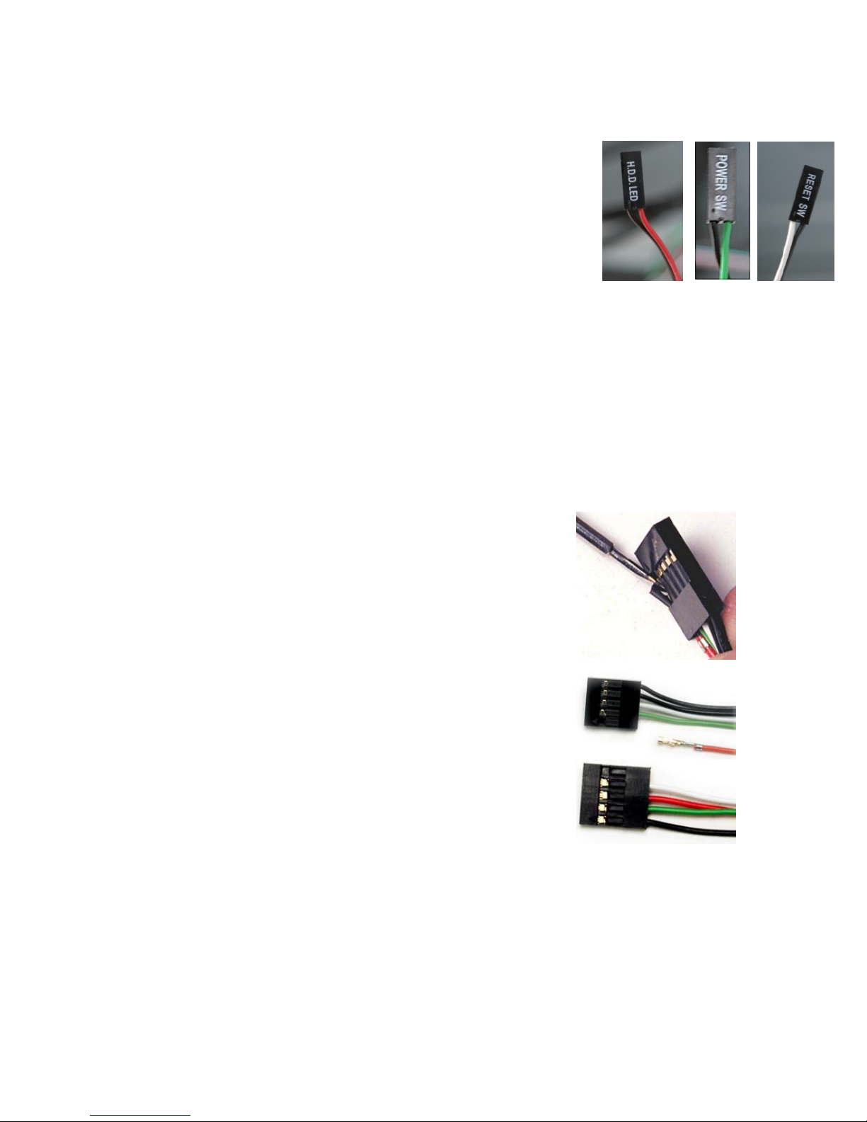
3.3
P
OWER
S
WITCH
/
R
ESET
S
WITCH
/
H
ARD
D
ISK
D
RIVE
LED
C
ONNECTORS
Connected to your front panel are LED and switch leads for power, reset, and
HDD LED activity. Attach these to the corresponding connectors on your
motherboard. Consult your motherboard manual for specific pin header
locations. For LEDs, colored wires are positive ( + ). White or black wires are
negative ( – ). If the LED does not light up when the system is powered on, try
reversing the connection. For more information on connecting LEDs to your
motherboard, see your motherboard user’s manual.
Note: Polarity (positive and negative) does not matter for switches.
3.4
R
EWIRING
M
OTHERBOARD
H
EADER
C
ONNECTIONS
There may come a time when you need to reconfigure the pin-out of a motherboard header connector.
Examples could be for your USB header, audio input header, or some other front panel connector such
as the Power Button connector.
Before performing any work, please refer to your motherboard user’s manual or your motherboard
manufacturer's website to be sure of the pin-out needed for your connector. We strongly recommend
making a notated drawing before beginning work so that you can recover if your work gets disturbed.
1. Determine which wires you need to remove in order to rewire your
plug to match the USB pin-outs on your motherboard (refer to your
motherboard user’s manual). Working on one connector at a time,
use a very small flathead screwdriver or similar tool to lift up on
the black tab located beside the gold posts (squares). This will
allow you to easily slide out the pins from the USB plug.
2. Working carefully so as not to damage the wires, connectors, or
pins, slowly remove the pin from the connector. Repeat these
steps for each wire you need to change.
. Working carefully so as not to damage the wires, connectors or
pins, slowly reinsert the pin into the correct slot of the connector
then snap closed the black tab that was lifted in step 1. Repeat
these steps for each wire you need to change.
Other manuals for TWO HUNDRED
1
Table of contents
Other Antec Computer Accessories manuals

Antec
Antec KS 282 User manual

Antec
Antec VSK-2000 User manual

Antec
Antec TITAN 550 550 User manual

Antec
Antec P180B Fan User manual

Antec
Antec ISK 300-150 User manual

Antec
Antec Nineteen Hundred User manual

Antec
Antec NSK 4400 User manual

Antec
Antec TWO HUNDRED User manual

Antec
Antec NSK 4000 User manual

Antec
Antec Twelve Hundred User manual

Antec
Antec NSK 6580 User manual

Antec
Antec Sonata III User manual

Antec
Antec Minuet 350 User manual

Antec
Antec P100 User manual

Antec
Antec NSK 4480 User manual

Antec
Antec SLK3700-BQE User manual

Antec
Antec Solo User manual

Antec
Antec SX830 User manual

Antec
Antec Six Hundred User manual

Antec
Antec Nine Hundred User manual


