4
H
ARDWARE
I
NSTALLATION
G
UIDE
.1
S
ETTING
U
P
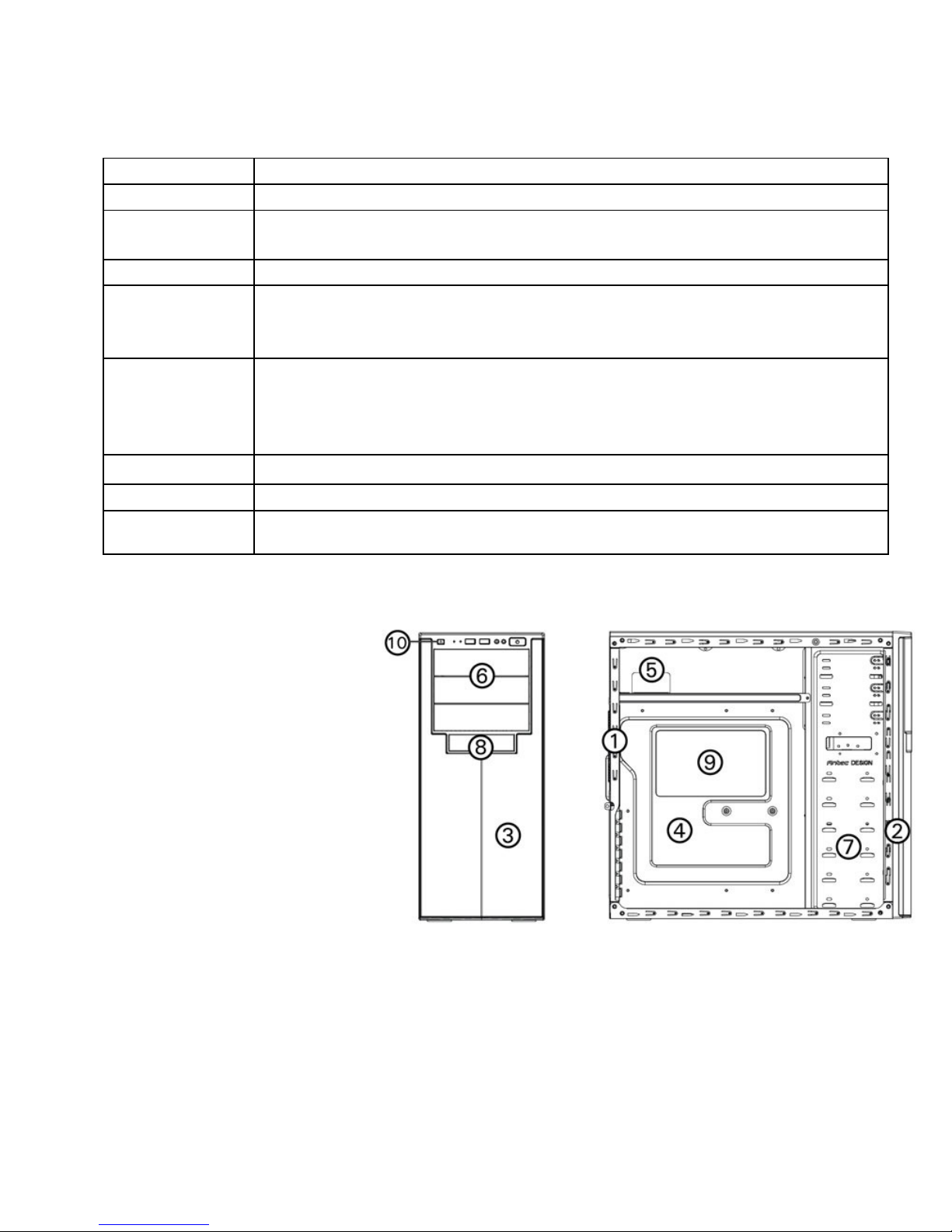
1.
Place the case upright o a flat, stable surface with the
rear of the case faci g you.
2. Remove the side pa els by first removi g the
thumbscrews at the rear of the case. The , grip each
pa el at the top a d bottom a d slide it toward the rear
of the case u til it detaches from the chassis.
3. To remove the fro t bezel, locate the three plastic tabs
o the left side of the bezel. They faste the fro t bezel
to the metal chassis. Release the tabs from the top dow
to release the bezel. Swi g the bezel ope to about 45°
a d ge tly lift the bezel upward, a d it will come off
easily. Set the bezel i a safe place.
Note
: Do ot use your fi ger ails to pry or lift the pa els.
.
P
OWER
S
UPPLY
I
NSTALLATION
1. With the case o its side, alig your power supply with
the power supply mou ti g locatio ear the top pa el
of the case.
Note:
Power supplies with fa s o the bottom of the
power supply will eed to be mou ted so that the
fa is faci g the bottom of the case.
2. Attach the power supply to the case with the screws
provided.
.3
C
ABLE
M
ANAGEMENT
There is a cable ma ageme t compartme t behi d the 3.5” drive cage.
You ca tuck or route excess cables i this compartme t.
1.
Ope the right side pa el as described i sectio 2.1.
2. Locate the cable ma ageme t compartme t with cable ties
located behi d the walls of the 3.5” drive cage.
3. Tuck or route your excess cables to the compartme t. This will
keep the cables from i terferi g with airflow i your case a d help
with cooli g.
4. Use the cable ties provided to hold them i place.