AP&T AP-AB1602A User manual

Explosion-proof Ion Bar Series
AP-AB1602A
Explosion-proof Ion Bar Series
AP&T
R
Shanghai Anping Static Technology Co.,Ltd
AP&T

Suitable for coating, printing, film and other industries with
flammable working conditions
E f f e c t i v e l y s o l v e t h e p r o b l e m s c a u s e d b y
s t a t i c e l e c t r i c i t y
Static Removal Prevent uneven scattering
Control ink splashing
Prevent adhesion of objects Prevent blockage of adhesion

产品适用于涂布、印刷、薄膜等有易燃工况的行业
This product can be used in flammable and explosive working places
corresponding to ⅡB or lower level with this safe explosion-proof function.
Can be used safely in flammable and explosive
environments
Explosion-proof certificate No.:GYB21.3386X Explosion-proof mark:Ex sc Ⅱ B T4 Gc

Ion bar adopts power frequency AC high voltage and
acts on the dedicated emitter electrode through
impedance coupling devices to ionize air molecules
to generate positive and negative high voltage ions
and transport them to the surface of the object to be
eliminated to neutralize positive and negative
electrostatic charges to achieve efficient and reliable
static elimination.
AC
High voltage power supply
Power frequency AC
T
Positive voltage working time
Negative voltage working time
+HV
(Positive high pressure)
-HV
(Negative high pressure)
-150 0 150
600
550
500
450
400
350
300
0.9
1.4
2.0
2.5
3.0
3.6
4.1
4.6
5.2
5.7
6.2
-150 0 150
600
550
500
450
400
350
300
33.6
37.2
40.7
44.3
47.8
51.4
55.0
58.5
62.1
65.6
69.2
Z(mm)
Y(mm)
-150 150
Discharge ability
Working way
High Efficiency Static Removal
Keep a clean production environment and stay
away from static electricity
Test Height Z (mm)
Test Height Z (mm)
Test Width Y (mm)Test Width Y (mm)
Discharge Time(s)
Ion Balance(V)
Discharge time distribution diagram of AP-AB1602A
with 1000mm bar length at 0.4MPa air pressure
Ion balance voltage distribution diagram of AP-AB1602A
with 1000mm bar length at 0.4MPa air pressure
Test bearing chart
Trek 150*150mm
plate tester
Vertical test distance
Horizontal test distance
front and back
Test standard:ANSI/ESD.STM3.1,SJ/T 11446—2013
Test instrument:Trek charge plate tester
Test voltage:±1000V → ±100V attenuation
Test environment:humidity 50±5%;temperature 23±3℃

Product model: AP-AB1602A
Power: 7KV 1 capacitor Test instrument: TREK158 Ion bar length:100cm
Test distance(mm)Air pressure
(MPa)1*
Discharge performance
Vertical Horizontal Positive discharge
time (S)
Negative discharge
time (S) MIN Balance voltage
AVE(V)MAX
300
-150
0.2
7.461 6.049 -59.4 35.35 130.1
0 1.525 1.397 -56.7 40.7 138.1
150 4.127 4.773 -65.8 40.3 146.4
-150
0.4
4.697 5.487 -34.6 54.6 143.8
0 0.888 0.778 -20.6 66.1 152.8
150 6.225 4.253 -98.9 33.65 166.2
-150
0.6
4.439 3.527 -21.4 69.3 160
0 0.706 0.571 -10 77.5 165
150 7.514 4.231 -78.8 51.65 182.1
500
-150
0.2
6.783 6.225 -36.7 28.85 94.4
0 2.785 2.487 3.4 52.35 101.3
150 5.16 4.349 -31.3 37.15 105.6
-150
0.4
3.295 3.46 28.1 69.15 110.2
0 1.683 1.408 13.9 66.4 118.9
150 3.213 2.911 -1.7 56.1 113.9
-150
0.6
3.164 2.785 29.1 77.3 125.5
0 1.506 0.98 44.7 92.05 139.4
150 3.646 2.324 24 78.55 133.1
600
-150
0.2
7.988 6.336 -14.7 35.35 85.4
0 3.128 2.794 -4.2 44.95 94.1
150 6.431 6.559 6.6 47.75 88.9
-150
0.4
4.254 3.215 11.4 56.35 101.3
0 2.178 1.814 24 65.45 106.9
150 3.498 2.733 0.7 51.8 102.9
-150
0.6
2.886 2.468 37.6 79.35 121.1
0 1.931 1.285 58.6 96 133.4
150 3.191 2.504 33.7 80.15 126.6
with air source
AP-AB1602A
150mm 150mm
300mm
0.7s 7.5s4.4s
500mm
1.5s 6.5s3.1s
600mm
1.9s 3.1s2.8s
150mm*150mm plate tester
Other test data

No.1
No.2
No.3
Easy installation
Hexagonal bolts are provided and put the
slider nut into the special strip notch on the
back of the bar body which are removable
to left or right and can be easily installed in
different environments.
CE certification
It can effectively avoid external
electromagnetic interference affecting
the normal operation of the ion bar
which is a high-security and high-
reliability static eliminator.
Features
Safe / Easy to use / Durable
Electroshock-proof
Protection against human electro-shock.

Model AP-AB1602A
Explosion-proof mark Ex sc Ⅱ B T4 Gc
Explosion-proof certificate No. GYB21.3386X
Working voltage Power frequency≤ AC7000V
Power 20W
Ion emission Power frequency AC
Emitter electrode SUS
Discharge structure Resistance coupling
Electrode high voltage ≤ 7000V
Electrode needle combined capacitance < 3.5pF
Discharge range (L*W*H) (110mm → 3000mm)*300mm*600mm
Installation distance 100 - 600mm
Air pressure ≤ 0.6MPa
Compressed air connector Φ8-G1/8 white
Ion balance ≤ |±50V|
Discharge speed ≤ 2.5S(Test data may vary with test conditions)
Working temperature 0℃ – 50℃
Working humidity < 70%
Bar material Flame retardant PVC、AL
Dimensions (L*W*H) (110mm → 3000mm)*28.6mm*38.7mm
Packaging accessories Hex bolt M5*20
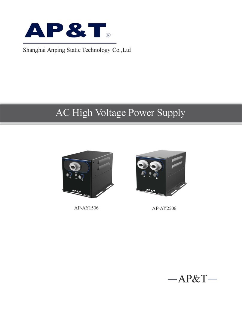
Power supply AP-AY1604/2604
Power cord 2.5m(Customizable upon request. Maximum 8m)
Warranty 1Year
Certification CE
Product specifications
Product details / Product specifications / Product size

Unit:mm
Stomata
Discharge electrode
High voltage plug
Sliding mounting bolt(M5×20 )
Shielded high voltage wire
Air source connector with throttle
Product size
Product details
Sliding mounting bolt(M5*20)
Discharge electrode
Stomata
Ground terminal
High voltage plug
Shielded high voltage wire
Air source connector with throttle
Ground terminal

① P lace the ion bar in the working area where static electricity is to be eliminated. The AP-AB1602A ion bar should be about 100~ 300mm
away from the surface of discharged object and the installation angle should be perpendicular to the surface of the charged body.
②The surface of ion bar is not allowed to be covered by other objects.
③Two AP-AB1602A ion bars should be installed side by side with an interval of more than 300mm and should be staggered by more than 300mm
if installed face-to-face.
④ More than 200mm away from obstacles such as walls.
⑤ Ion bar should be at least 30mm away from the metal conductor and metal grounding body around the electrode. And the bar body must be
reliably connected to the AC equipment grounding wire and the grounding resistance should be less than 1 ohms.
Warning It is necessary to ensure that the air is dry and clean when using a compressed air source to enter the ion bar to avoid the moisture,
grease, and dust in the air source from contaminating electrode needles causing high-voltage insulation failure which affects normal use.
Installation distance
Discharged object
≥ 300mm
≥ 300mm
Step of use
Installation position
Galvanized Hexagon Bolt 1LML05000 M5
Hex nuts 1SL00520X M5*20
Packing accessories
Products Use
Step of use/Installation position/Packing accessories
①Select the best static discharge position and install the bar body and the supporting
power supply firmly.
②Insert the high-voltage plug of the bar body into the high-voltage output connecting
seat of the supporting high-voltage power supply.
③Connect the grounding terminal of the bar body to the grounding stud of the high
voltage power supply.
④Connect the air source connector on bar body(air source type) to the air source
generating device and turn on the air source switch.
⑤Turn on the power switch and indicator light on shows the power work. Adjust
the proper air source pressure to generate positive and negative ions at the
electrode needles to neutralize the surface static electricity of the object.
WALL
WALL
WALL
WALL
Metal conductor
Metal conductor
Metal conductor
Metal conductor
Part name Picture Part No. Specification

Special conditions for the safe use of products
The suffix “X” of the explosion-proof certificate No. indicates that the product has special conditions for safe use. The specific contents are as
follows:
•The product cannot be used in places where conductive objects may adhere to the static elimination electrodes (Static eliminating
electrodes may not work when attached to conductive materials such as carbon and metal foil).
•It should be more than 20mm away from the static elimination object when the static elimination electrode is installed.
•The distance between the static elimination electrode and the mechanical frame should be more than 10mm.
•Keep the static-eliminating electrode clean and it is strictly forbidden to dry-clean the static-eliminating electrode support.
•The power supply unit which does not have an explosion-proof structure must be installed in a non-hazardous location.
•The maximum length of high-voltage cable is 8m.
•It is strictly forbidden to open the cover.
•It is strictly forbidden to rub the surface of the product shell to prevent the risk of static electricity ignition.
Precautions for product use
•The environment range of products allowed to use:
Temperature:(0 ~ +50)℃Relative humidity::35% ~ 75%
Altitude:not more than 1000m
•The product is equipped with a grounding terminal, users should ground it reliably during installation and use.
•The principle of “No opening with power on” must be observed during on-site use and maintenance of the product.
•Users are not allowed to replace parts or components of this product by themselves and should work with the product
manufacturer to solve the faults in operation to prevent damage.
•The electrical parameters of the eliminator are as follows:
Discharge device Static elimination electrode Power supply unit
Model Voltage(V) Frequency (Hz) Needle binding capacity(pF/ group) Primary voltage(V) Secondary voltage (V) Frequency (Hz) Capacity (VA) Insulation class
AP-AB1602A ≤ 7000 50 3.5
100
≤ 7000 50 25 E110
220
Warning
Warning
•The installation, use and maintenance of the product should also abide by the product manual and the requirements of the following related
standards and specifications:
GB 3836.13–2013 Explosive environment Part 13: Repair, overhaul, repair and modification of equipment
GB 3836.15–2000 Electrical equipment for explosive gas atmospheres Part 15: Electrical installations in hazardous locations (except coal mines)
GB 3836.16–2006 Electrical equipment for explosive gas atmospheres Part 16: Inspection and maintenance of electrical devices (except coal mines)
GB 50257-2014 Explosion and fire hazard environment of electrical equipment installation engineering construction and acceptance specification for electrical equipment
GB 3836.18–2010 Explosive environment Part 18: Intrinsically safe system
•Read the operating instruction carefully before installing and using the device.
•The whole equipment must be reliably connected to the ground of the AC equipment and the grounding resistance is less than 1 ohms
during use; Otherwise, it is easy to cause abnormal or even damage of ion bar.
•It is strictly forbidden to disassemble products without authorization. Internal maintenance and repair must be carried out by professional
personnel.
•The product is strictly prohibited to touch liquid during use, otherwise there will be abnormal, resulting in electric shock or fire.
•Power must be turned off during inspecting or replacing the product, otherwise it may cause electric shock or fire.
•The product is specially designed for removing static electricity and is strictly prohibited for other purposes. Any abnormal use may
cause machine failure, electric shock, fire and other hidden dangers.
•It is strictly forbidden to touch the electrode needles when power is on, otherwise it is easy to cause fault and electric shock accident.
•Discharge needle is a sharp metal object, please use it with care.
•Please check the specifications of the power supply before powering on the product. Any power supply that does not meet the
specifications may cause damage or even failure to the product.
•Check the power cord regularly. If it is damaged, replace it immediately; otherwise, leakage and abnormal operation may occur.
Operation guide
Trouble shooting
Maintenance
After-sales service
1.Select the best static discharge position and install the bar body and the supporting power supply firmly.
2.Insert the high-voltage plug of the bar body into the high-voltage output connecting seat of the supporting high-voltage power supply.
3.Connect the grounding terminal of the bar body to the grounding stud of the high voltage power supply.
4.Connect the air source connector on bar body(air source type) to the air source generating device and turn on the air source switch. (The
compressed air source must be equipped with a filter to ensure that the air is dry and clean to avoid the moisture, grease in the flow
affecting the insulation performance of the ion bar. )
5.Turn on the power switch and indicator light on shows the power work. Adjust the proper air source pressure(air pressure ≤ 0.6MPa) to
generate positive and negative ions at the electrode needles to neutralize the surface static electricity of the object.
1、Do not disassemble the equipment.
2、Do not short-circuit the high-voltage power cable to avoid permanent damage to the power supply.
3、Please check the product power cable regularly, and replace it immediately if it is damaged, otherwise it is easy to cause problems such as
electric leakage and abnormal work.
4、The power supply should be stored in a cool and dry environment.
5、Stop using immediately and send the power supply to Anping Company for processing if abnormalities or problems are found during use.
NO Problems Reasons Solutions Remark
1
The discharge electrode
ignites the ground electrode
on the side of the bar body
Dust accumulation on bar
body causes a decrease in the
surface insulation resistance
The carbon deposits on the
discharge electrode and bar
body should be cleaned and
maintained regularly with
electrostatic brush, dust-free
cotton swab, dust-free cloth
dipped in anhydrous alcohol
according to the use
environment and the required
electrostatic protection
requirements in order to
ensure the good performance
of the product
2
The discharge electrode
ignites other metal
grounding bodies
The bar body is installed
too close to other metal
grounding bodies
Power off and clean bar body
Move the installation position of the bar
body and keep it more than 50mm away
from other metal grounding bodies to
ensure safe use and discharge performance
3
The electrostatic
removal performance
is obviously reduced
Discharge needle is
polluted and damaged Clean or replace the ion bar
Bearing set of ion bar
is improper Confirm the best bearing set
4The electrostatic
removal performance
is reduced
There are conductors or
other ion bars around Remove conductors or other ion bars
5Unable to discharge
High-voltage connecting
wire is damaged Return to factory for maintenance
Ion bar insulation is damaged Return to factory for maintenance
Poor grounding/no grounding Check the electrical grounding of ion
bar and plant equipment
6Product burnout Ion bar insulation is damaged Return to factory for maintenance
1. AP-ABAP-AB1602A explosion-proof ion bar has undergone rigorous testing and aging treatment before ex-work. Its performance
has completely reached the relevant indicators marked in the usage instruction.
2. AP&T makes a commitment to the customer that any defective parts inspected by AP&T will be repaired or replaced free of charge
within one year from the date of purchase. However, this commitment does not apply to:
(1) The device is incorrectly used or installed.
(2) Damage caused by negligence or accident during use.
(3) Modified, disassembled or repaired by other service departments not authorized by Anping Company.
3. AP&T shall not be liable for any incorrect use of the products except for repair or replacement of parts as specified above.

专业创造价值
AP&T
Professional electrostatic intelligent monitoring/analysis
and elimination solution provider
Speciality Creates Value
AP&T
Shanghai Anping Static Technology Co.,Ltd
Tel : +86-21-64517676
Fax : +86-21-64517673
Postcode : 200233
Website : www.ap-static.com
Address : 3/F,Building 27,No.69,Guiqing Road,Shanghai,China
Table of contents
Other AP&T Power Supply manuals

AP&T
AP&T AP-DC7201 User manual

AP&T
AP&T AP-AB1208 User manual

AP&T
AP&T AP-DY6702 User manual

AP&T
AP&T AP-AB1208 User manual

AP&T
AP&T AP-AY1505 User manual

AP&T
AP&T AP-AC2455 Series User manual

AP&T
AP&T AP-DY7221 Specification sheet

AP&T
AP&T AP-AB1216 User manual

AP&T
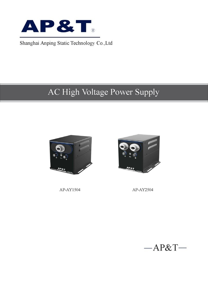
AP&T AP-AY1504 User manual

AP&T
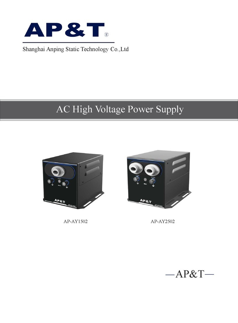
AP&T AP-AY1502 User manual