Aplex ACS-2110 User manual

ACS-2110 User Manual
1
ACS-2110 Box PC
User Manual
Release Date Revision
Nov 2011 V1.0
Jun 2013 V1.1
® 2011 Aplex Technology, Inc. All Rights Reserved. Published in Taiwan
Aplex Technology, Inc.
15F-1, No.186, Jian Yi Road, Zhonghe District, New Taipei City 235, Taiwan
Tel: 886-2-82262881 Fax: 886-2-82262883 E-mail: aplex@aplex.com.tw URL: www.aplex.com.tw

ACS-2110 User Manual
2
Warning!_______________________________
This equipment generates, uses and can radiate radio frequency energy and if not installed and
used in accordance with the instructions manual, it may cause interference to radio
communications.
It has been tested and found to comply with the limits for a Class A computing device pursuant to
FCC Rules, which are designed to provide reasonable protection against such interference when
operated in a commercial environment. Operation of this equipment in a residential area is likely
to cause interference in which case the user at his own expense will be required to take whatever
measures may be required to correct the interference.
Disclaimer
This information in this document is subject to change without notice. In no event shall Aplex
Technology Inc. be liable for damages of any kind, whether incidental or consequential, arising
from either the use or misuse of information in this document or in any related materials.
Electric Shock Hazard –Do not operate the machine with its back cover removed. There are
dangerous high voltages inside.

ACS-2110 User Manual
3
Packing List
Accessories (as ticked) included in this package are:
□AC power cable
□Driver & manual CD disc
□Other.___________________(please specify)
Safety Precautions
Follow the messages below to avoid your systems from damage:
◆Avoid your system from static electricity on all occasions.
◆Prevent electric shock. Don‘t touch any components of this card when the card is
power-on. Always disconnect power when the system is not in use.
◆Disconnect power when you change any hardware devices. For instance, when you
connect a jumper or install any cards, a surge of power may damage the electronic
components or the whole system.

ACS-2110 User Manual
4
Table of Contents______________________
Warning!…………………………………………………………………………….……..….2
Disclaimer………………………………………………………………….…………………2
Chapter 1 Getting Started
1.1 Features…....………………….………………………….…………..…...…6
1.2 Specifications………………………………………….………….……...…..6
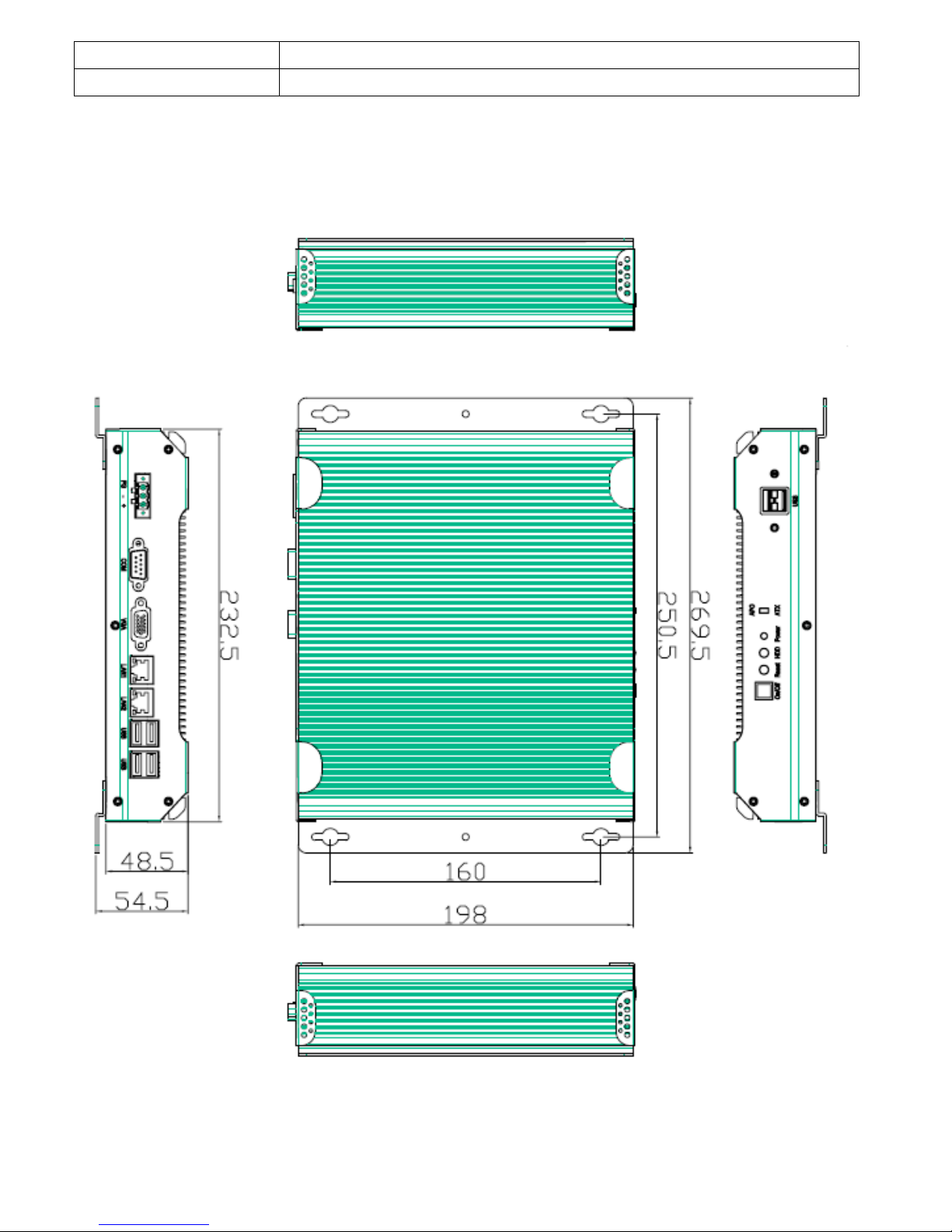
1.3 Dimensions…………………………………...……………….…………......7
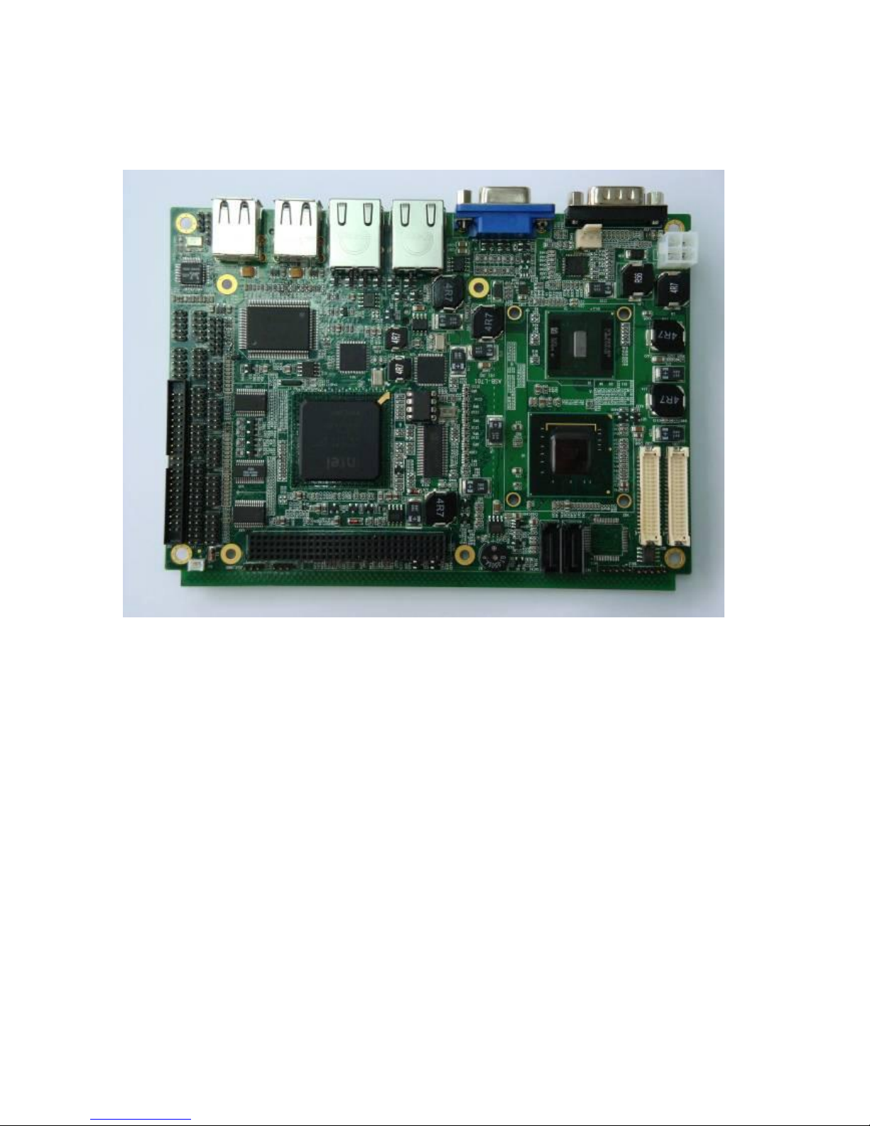
1.4 Brief Description of ACS-2110………..………………….…………………8
Chapter 2 Hardware Installation
2.1 Mainboard Specifications………………………..…………….……………9
2.2 Installations…………………………………………………….……………15
2.3 Onboard Jumpers and Port Pin outs………….…………….……………16
Chapter 3 BIOS Setup
3.1 Operations after POST Screen.............................................................26
3.2 Standard CMOS Features....................................................................28
3.3 Advanced BIOS Features.....................................................................31
3.4 Advanced Chipset Features Setup...................................................... 34
3.5 Integrated Peripherals......................................................................... 38
3.6 Power Management Setup.................................................................. 44
3.7 PnP/PCI Configurations Setup............................................................ 47
3.8 PC Health Status................................................................................. 49
3.9 Load Fail-Safe/Optimized Defaults.......................................................50
3.10 Set Administrator/User Password.......................................................52
3.11 Save & Exit Setup...............................................................................53
3.12 Exit Without Saving.............................................................................54

ACS-2110 User Manual
5
Chapter 4 Installation of Drivers
4.1 Intel Chipset Driver.…………………………...……………………………56
4.2 Intel Graphics Media Accelerator Driver...…....………………….......…..59
4.3 Realtek GbE & FE Ethernet PCI-E NIC Driver……...................……….63
4.4 Realtek HD Audio Driver Installation…….…………..…………………66
Figures
Figure 1.1: Dimensions of the ACS-2110 ……..……………………………...7
Figure 1.2: Front View of ACS-2110………………….....……………………...8
Figure 1.3: Rear View of ACS-2110…..……………………...………………...8
Figure 2.1: Mainboard Overview……………………………………………..…9
Figure 2.2: Mainboard Dimensions……………………………………………10
Figure 2.3: Connector and Jumper Locations…………………………..……12
Figure 2.4: Installation of Memory Module……………………………………15

ACS-2110 User Manual
6
Chapter 1________________Getting Started
1.1 Features
Fanless design
Slim size
Selectable AT/ATX mode power switch
All solid capacitor motherboard
Wide range DC 11~32V power input for option
1.2 Specifications
Model No.
Specs
ACS-2110
CPU
Intel Atom N270 1.6GHz processor FSB 533MHz
Chipset
Intel 945GSE + ICH7M chipset
System Memory
1 x 200 Pin SO-DIMM socket, support 533MHz up to 2GB SDRAM
Storage support
1 x 2 .5" SATA HDD Space
1 x CF slot On board (internal)
External I/O Port
Rear I/O
4 x USB 2.0 connector
2 x RJ-45 LAN connector
1 x DB-9 RS232(COM1)
1 x DB-15 VGA
1 x 3-Pin DC Terminal by TB-323
Front I/O
1 x Switch Board by TB-2000
1 x DB9 RS232(COM2, RS232/422/485 select, Default RS232)
1 x DB9 RS232
Expansion Slots
None
Power Input
12V DC, optional 11~32V DC
OS support
Windows XP, Windows XP Pro, XP Embedded, Windows Embedded
Standard 7
Construction
Aluminum Molding Heat sink + Heavy Duty steel Chassis
Color
Black
Mounting
Wall Mount
Dimensions (WxHxD)
232.5(W)x198(H)x48.5(D) mm
Net Weight
2kgs
Operating Temperature
0~50 ゚C
Storage Temperature
-20~60 ゚C

ACS-2110 User Manual
7
Storage Humidity
10~90% @40 ゚C non-condensing
Certificate
CE/FCC Class A
1.3 Dimensions
Figure 1.1: Dimensions of the ACS-2110

ACS-2110 User Manual
8
1.4 Brief Description of the ACS-2110
The ACS-2110 is a Fan-less High-efficiency Thermal Solution and ultra-compact standalone Box PC,
powered by an Intel Atom N270 1.6GHz and supporting 6 x USB 2.0 ports, 1 x COM Port, 1 x VGA, 1 x
SATA HDD, 1 x internal CF slot etc. It is ideal for kiosks, POS systems, airport terminal controllers,
digital entertainments, etc. and running factory operations from small visual interface and maintenance
applications to large control process applications. The ACS-2110 works very well along with any of our
Display Monitor series. It absolutely can provide an easy way to perform control and field maintenance.
It comes with a DC11~32V wide-ranging power input for option.
Figure 1.2: Front View of ACS-2110

ACS-2110 User Manual
9
Figure 1.3: Rear View of ACS-2110
Chapter 2__________Hardware Installation
2.1 Mainboard Specifications
Figure 2.1: Mainboard Overview

ACS-2110 User Manual
10
Figure 2.2: Mainboard Dimensions

ACS-2110 User Manual
11

ACS-2110 User Manual
12
Figure 2.3: Connector and Jumper Locations

ACS-2110 User Manual
13
Mainboard Specifications
Board Size
165 x 115mm
CPU Support
Intel Atom N270 1.6 GHz with 533MHz FSB
Chipset
Intel 945GSE + Intel ICH7M
Memory Support
1x200pin 533/400MHz DDR2 SO-DIMM support, up to 2GB
SDRAM
Graphics
Intel Graphics Media Accelerator 950VGA integrated in Intel
945GSE
18-bit dual-channel LVDS integrated in Intel 945GSE
18/24 bit dual-channel LVDS support by Chrontel CH7308B
1 x DB15 Female connector for external
Super I/O
Winbond W83627UHG
BIOS
Award BIOS
Storage
2 x SATA Connector
1 x Compact Flash II Slot
1 x 44-pin IDE Connector
Network
2 x Gigabit Ethernet Port by RJ45 with LED indicators - Ethernet
controller :
2 x PCIe by one bus Realtek 8111D
USB
4 x USB 2.0 stack port for external
2 x USB 2.0 header for internal
Serial
1 x RS232 port, DB9 connector for external (COM1),
pin 9 w/5V/12V/Ring select
1 x RS232/422/485 (Full-duplex) select header for internal
(COM2), default RS232
4 x RS232 header for internal (COM3 –COM6)
Digital I/O
8-bit digital I/O by header
4-bit digital Input
4-bit digital Output
Battery
Support CR2477 battery by 2-pin header
Audio
Support Audio via Realtek ALC662 HD audio decoder
Support Line-in, Line-out, MIC by 2x5-pin header
Printer
1x LPT port by 2x13-pin header
Keyboard
/Mouse
1x PS2 keyboard/mouse by 1x6 -pin wafer connector

ACS-2110 User Manual
14
Expansion Bus
1x PC 104+ connector (PCI master 4, jumper for +3.3V & 5V
select)
1x PCIe ( PCI-e 1x +SMBUS+USB2. 0 ) mini card
Power
Management
DC12V input
1 x 2x2-pin power input connector
Front I/O
by 2x5-pin header
Power on/off switch
Reset switch
Power LED status
HDD LED status
Buzzer
Watchdog Timer
Software programmable 1 –255 second by Super I/O
External I/O port
1 x COM Port (COM1)
4 x USB 2.0 Ports (stack)
2 x RJ45 GbE Port (10/100/1000Mbps)
1 x VGA Port
Temperature
Operating: 0 –60 degree C
Storage: -20 –80 degree C
Humidity
5% - 95%, non-condensing, operating
Power
Consumption
12V @1.4 5A (Intel N270 processor with 1GB DDR2 DRAM)
EMI/EMS
CE/FCC class A

ACS-2110 User Manual
15
2.2 Installations
2.2.1 SO-DIMM Installation
To install a SO-DIMM into a SO-DIMM socket, please follow the steps below and refer to picture.
Figure 2.4: Installation of Memory Module
Step 1:
Locate the SO-DIMM socket. Place the NANO-945GSE2 on an anti-static pad with the solder side
facing up.
Step 2:
Align the SO-DIMM with the socket. The SO-DIMM must be oriented in such away that the notch in
the middle of the SO-DIMM must be aligned with the plastic bridge in the socket.
Step 3:
Insert the SO-DIMM. Push the SO-DIMM chip into the socket at an angle. (See Figure 2.3)
Step 4:
Open the SO-DIMM socket arms. Gently pull the arms of the SO-DIMM socket out and push the rear
of the SO-DIMM down

ACS-2110 User Manual
16
2.3 Onboard Jumpers and Port Pin outs
1. JVCCIO (2.0MM 1X3) PC104+ port voltage selection jumper: select voltage for
PC104+ device
JVCCIO
PC104+ VCCIO Voltage
CLOSE 1-2
+3.3V (default)
CLOSE 2-3
+5V
2. JCLR_CMOS (2.0MM 1X3) CMOS clear jumper: CMOS clear operation will
permanently reset old BIOS settings to factory defaults.
JCLR_CMOS
CMOS
CLOSE 1-2
NORMAL (default)
CLOSE 2-3
CLEAR CMOS
Procedures of CMOS clear:
1. Turn off the system and unplug the power cord from the power outlet;
2. To clear the CMOS settings, use the jumper cap to close pins 2 and 3 for about 3 seconds
then reinstall the jumper clip back to pins 1 and 2.
3. Power on the system again;
4. When entering the POST screen, press the <DEL> key to enter CMOS Setup Utility to load
optimal defaults;
5. After the above operations, save changes and exit BIOS Setup.
3. BAT (1.25.0MM 1X2) Battery port: a 3.3V battery is embedded to provide power for
CMOS.
PIN#
Signal Name
PIN1
VBAT
PIN2
Ground

ACS-2110 User Manual
17
4.COM2-COM6 (2.0MM 2X5)COM2~COM6 port: up to 5 standard RS232 ports are
provided. They can be used directly via COM adapter cable connection.
Signal Name
Pin#
Pin#
Signal Name
DCD
1
2
RXD
TXD
3
4
DTR
Ground
5
6
DSR
RTS
7
8
CTS
RI
9
10
NC
Note: COM2 port is controlled by pins No.8~10 of JCOM. For details, please refer to
description of JCOM.
5.KB/MS (2.0MM 1X6) PS/2 keyboard/mouse port: the port can be connected to PS/2
keyboard or mouse via a dedicated adapter cable for direct use.
Pin#
Signal Name
1
KBDATA
2
MSDATA
3
Ground
4
+5V
5
KBCLK
6
MSCLK
6. LPT (2.0MM 2X13)Parallel port: a standard 26 pin parallel port is provided to connect
parallel peripherals as required.
Signal Name
Pin#
Pin#
Signal Name
PSTB#
1
2
PD0
PD1
3
4
DP2
DP3
5
6
DP4
DP5
7
8
DP6
DP7
9
10
ACK#

ACS-2110 User Manual
18
BUSY
11
12
PE
SLCT
13
14
AFD#
ERR#
15
16
INIT#
SLIN#
17
18
Ground
Ground
19
20
Ground
Ground
21
22
Ground
Ground
23
24
Ground
Ground
25
26
Ground
7. GPIO (2.0MM 2X5) General-purpose input/output port: it provides a group of
self-programming interfaces to customers for flexible use.
Signal Name
Pin#
Pin#
Signal Name
GPIO20
1
2
GPIO60
GPIO21
3
4
GPIO61
GPIO22
5
6
GPIO62
GPIO23
7
8
GPIO63
Ground
9
10
+5V
8. COM22 (2.0MM 2X5): it provides selectable RS422/485 serial signal output.
Signal Name
Pin#
Pin#
Signal Name
A
1
2
Terminal
Resistance
B
3
4
Terminal
Resistance
Z
5
6
NC
Y
7
8
NC
Ground
9
10
NC
9. USB4 (2.0MM 2X5) Front USB connector: it provides two USB ports via a dedicated
USB adapter cable.
Signal Name
Pin#
Pin#
Signal Name
+5V
1
2
+5V
USB_P6_DN
3
4
USB_P7_DN
USB_P6_DP
5
6
USB_P7_DP
Ground
7
8
Ground

ACS-2110 User Manual
19
NC
9
10
Ground
Note:
Before connection, make sure that pin out of the USB adapter is in accordance with that of the
said tables. Any inconformity may cause system down and even hardware damages.
10. JCOM (2.0MM 2X6) COM1/2 setup jumper: pin 1~6 are used to select signal out of pin
9 of COM1 port; pin 7~12 are used to select output type for COM2 port (RS232 or RS422/485
Full-Duplex).
JCOM
Function
CLOSE 1-2
COM1 Pin9=RI (default)
CLOSE 3-4
COM1 Pin9=+5V
CLOSE 5-6
COM1 Pin9=+12V
CLOSE 7-9
CLOSE 8-10
COM2 FOR RS232 FROM COM2
(default)
CLOSE 9-11
CLOSE 10-12
COM2 FOR RS485/RS422 FROM
COM22
Note:
1. As determined by its hardware design, the board features full-duplex RS485 communication.
Like RS422, a four-wire connection is necessary.
2. Since COM2 and COM22 use the same address, they cannot work at the same time.
11. IDE (2.0MM 2X22) IDE connector: the motherboard provides a 44-pin IDE connector for
connection of 2.5' IDE hard disk drivers and supports up to 2 IDE devices.
Signal Name
Pin#
Pin#
Signal Name
RESET
1
2
Ground
IDE_PDD7
3
4
IDE_PDD8
IDE_PDD6
5
6
IDE_PDD9
IDE_PDD5
7
8
IDE_PDD10
IDE_PDD4
9
10
IDE_PDD11
IDE_PDD3
11
12
IDE_PDD12
IDE_PDD2
13
14
IDE_PDD13
IDE_PDD1
15
16
IDE_PDD14
IDE_PDD0
17
18
IDE_PDD15
Ground
19
20
NC
DREQ
21
22
Ground

ACS-2110 User Manual
20
IOW#
23
24
Ground
IOR#
25
26
Ground
IOCHRDY
27
28
Ground
DACK#
29
30
Ground
IRQ14
31
32
NC
Address 1
33
34
IDE_PDIAG
Address 0
35
36
Address 2
Chip select 0
37
38
Chip select 1
Activity
39
40
Ground
+5V
41
42
+5V
Ground
43
44
NC
Note:
If two IDE devices are connected, CF card connection cannot be realized.
12. F_PANEL (2.0MM 2X5) Front panel connector
Signal Name
Pin#
Pin#
Signal Name
HD LED+
1
2
POWER
LED+
HD LED-
3
4
POWER LED-
Ground
5
6
PWRBTN
RESET
7
8
Ground
BUZZER+
9
10
BUZZER-
PIN1&3: They are used to connect hard disk activity LED. The LED blinks when the hard disk is
reading or writing data.
PIN2&4: They are used to connect power LED. When the system is powered on or under S0/S1
state, the LED is normally on; when the system is under S4/S5 state, the LED is off.
PIN5&6: They are used to connect power switch button. The two pins are disconnected under
normal condition. You may short them temporarily to realize system startup & shutdown or
awaken the system from sleep state.
PIN7&8: They are used to connect reset button. The two pins are disconnected under normal
condition. You may short them temporarily to realize system reset.
PIN9&10: They are used to connect an external buzzer.
Note:
When connecting LEDs and buzzer, pay special attention to the signal polarity.
Make sure that the connector pins have a one-to-one correspondence with chassis wiring, or it
may cause boot up failure.
Table of contents
Other Aplex Desktop manuals

Aplex
Aplex ViTAM-915P User manual

Aplex
Aplex ACS-2645 User manual

Aplex
Aplex ARMPAC-6 Series User manual

Aplex
Aplex ACS-2320 User manual

Aplex
Aplex APC-3X95P_R User manual

Aplex
Aplex ACS-2310 User manual

Aplex
Aplex APC-3X18 User manual

Aplex
Aplex ACS-2170 User manual

Aplex
Aplex ACS-2675C Box PC User manual

Aplex
Aplex ACS-2630 User manual

Aplex
Aplex ACS-2120 User manual

Aplex
Aplex ACS-2210A User manual

Aplex
Aplex ACS-2685 User manual

Aplex
Aplex VIPAC-915 P User manual

Aplex
Aplex APC-3514 User manual

Aplex
Aplex APC-3784A/85A User manual

Aplex
Aplex ACS-2695A User manual

Aplex
Aplex AHM-6159P User manual

Aplex
Aplex ACS-2310 User manual

Aplex
Aplex ACS-2695 User manual