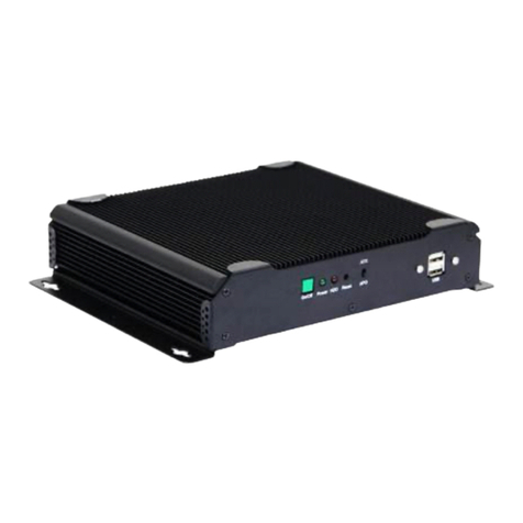
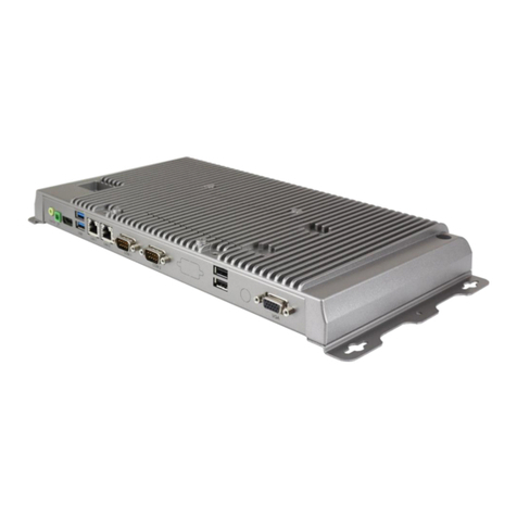
Aplex ACS-2310 User manual

ACS-2310 User Manual 1
Revision History
Reversion
Date
Description
1.0
2016/02/16
Official Version

ACS-2310 User Manual 2
Warning!___________________________
Disclaimer
This information in this document is subject to change without notice. In no event
shall Aplex Technology Inc. be liable for damages of any kind, whether incidental or
consequential, arising from either the use or misuse of information in this document
or in any related materials.
Electric Shock Hazard –Do not operate the machine with its back cover removed.
There are dangerous high voltages inside.
This equipment generates, uses and can radiate radio frequency energy and if
not installed and used in accordance with the instructions manual, it may cause
interference to radio communications. It has been tested and found to comply with
the limits for a Class A computing device pursuant to FCC Rules, which are designed
to provide reasonable protection against such interference when operated in a
commercial environment. Operation of this equipment in a residential area is likely
to cause interference in which case the user at his own expense will be required to
take whatever measures may be required to correct the interference.

ACS-2310 User Manual 3
Packing List
Accessories (as ticked) included in this package are:
□Adaptor
□Driver & manual CD disc
□Other.___________________(please specify)
Safety Precautions
Follow the messages below to prevent your systems from damage:
◆Avoid your system from static electricity on all occasions.
◆Prevent electric shock. Don‘t touch any components of this card when
the card is power-on. Always disconnect power when the system is not in
use.
◆Disconnect power when you change any hardware devices. For instance,
when you connect a jumper or install any cards, a surge of power may
damage the electronic components or the whole system.

ACS-2310 User Manual 4
Table of Contents
Revision History…….……………..………………………………………………..……………………………….1
Warning!/Disclaimer………............................……………………………….……………….……..….2
Packing List/Safety Precautions…......……………..……………………………..………………………..3
Chapter 1 Getting Started
1.1 Features………………………………….………..……………………………………5
1.2 Specifications……………………………….………….………………………………5
1.3 Dimensions……………………………………………..……………………………….6
1.4 Brief Description of ACS-2310……………………………………..……………7
Chapter 2 Motherboard
2.1 Motherboard Specifications…...……………..……………………….…..…..8
2.2 Motherboard Layout…………….…………….………………………..……....10
2.3 I/O Panel…………………………………………………………………………………12
2.4 Installation……………………………….…………………………………………….13
2.5 Jumpers Setup………………………………………………………………………..15
2.6 Onboard Headers and Connectors………………………………………….17
Chapter 3 UEFI SETUP UTILITY
3.1 Introduction…………………………....................................................22
3.2 Main Screen…………....................................................................23
3.3 Advanced Screen........................................................................24
3.4 Hardware Health Event Monitoring Screen...............................32
3.5 Security Screen...........................................................................33
3.6 Boot Screen….............................................................................34
3.7 Exit Screen……….........................................................................36
Chapter 4 Installation of Drivers
4.1 Intel new AtomTM Baytrail Chipset………….…………………………….38
4.2 Intel(R) VGA Chipset…………………………….………………....…………..…41
4.3 LAN Driver………………….…….…..……………………………….………………44
4.4 Realtek Audio Driver…………………………………..………………….………46
4.5 USB 3.0 Driver………………………………………………………………………..48
4.6 Com Driver……………………………………………………………………..........51
4.7 TXE Driver……………………………………………………………………………….53
Figures
Figure 1.1: Dimensions of ACS-2310…………....…………………………..…...6
Figure 1.2: Front View of ACS-2310………………………………….......……...7
Figure 1.3: Rear View of ACS-2310……………………………………..………....7
Figure 2.1: Motherboard SBC-210 Layout………………….………...………10

ACS-2310 User Manual 5
Chapter 1 Getting Started
1.1 Features
Intel Celeron N2930 1.83 GHz Processor
Fanless Design
1 x SO-DIMM DDR3L 1333MHz, up to 4G
9~36V DC Wide-ranging Power Input
Ultra Slim
1 x 2.5”SATA2 HDD Space
1.2 Specifications
System
Processor
Intel Celeron N2930 1.83GHz Processor
System Chipset
SoC
System Memory
1 x SO-DIMM DDR3L 1333MHz, up to 4G
Outside I/O
Front I/O Ports
2 x USB 3.0 type A
2 x GbE LAN RJ-45
1 x Line Out
1 x VGA
1 x 3-pin DC power input terminal
Rear I/O Ports
3 x RS-232 DB-9
4 x USB 2.0 type A
1 x Power Button
Storage
Storage
1 x 2.5”SATA2 HDD Bay
Expansion
Expansion Slots
1 x Mini-PCIe slot half size
1 x Mini-PCIe slot full size (shared with mSATA)
Power
Power Input
9~36V DC
Power Consumption
MAX: 16.1W
Mechanical
Construction
Plating Titanium Gray Aluminum Heatsink and Black Steel Chassis
Dimension
207 x 130 x 35.5 mm
Net Weight
1 Kg

ACS-2310 User Manual 6
Environmental
Operating Temperature
0~50 °C
Storage Temperature
-20~60 °C
Storage Temperature
10%~90%@ 40°C , non-condensing
Certificate
CE / FCC Class A
Operating System
Support
Windows Embedded 8.1 Industry Pro,
Windows 7 Pro for Embedded,
WES7,
WE8S
1.3 Dimensions
Figure 1.1: Dimensions of ACS-2310

ACS-2310 User Manual 7
1.4 Brief Description of ACS-2310
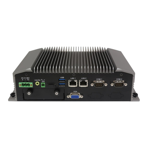
The ACS-2310 is a fanless design high-efficiency ultra slim BOX PC, powered by
Intel Celeron N2930 1.83GHz processor and supports 1 x SO-DIMM DDR3L 1333MHz
up to 4G memory. It comes with 2 x USB 3.0, 1 x VGA, 2 x LAN, 1 x line out, 4 x USB 2.0,
3 x RS-232 DB-9, and 1 x power button. It supports 1 x 2.5”SATA2 HDD space and
9~36V DC wide-ranging power input. The model has 1 x Mini-PCIe half size slot and 1 x
Mini-PCIe slot full size (shared with mSATA) for expansion. The model is plating
titanium gray aluminum heatsink and black steel chassis design. The ACS-2310 works
very well along with any of our display series and it absolutely can provide an easy way
to perform control and field maintenance.
Figure 1.2: Front View of ACS-2310
Figure 1.3: Rear View of ACS-2310

ACS-2310 User Manual 8
Chapter 2 Motherboard
2.1 Motherboard Specifications
Specifications
Form Factor
Dimensions
3.5”SBC (5.8-in x 4.0-in) / (148 x 102 mm)
Processor
System
CPU
Intel® new AtomTM Baytrail-M/D
Core Number
4
Max Speed
(By CPU)
Cache
(By CPU)
Chipset
N/A
BIOS
UEFI
Expansion
Slot
PCI
0
Mini-PCIe
1 (Half Size) + 1 (Full Size) shared with mSATA
mSATA
1 (Full Size) shared with SATAII_2`
PCIe
0
CFast Card Socket
0
Memory
Technology
Single Channel DDR3L 1066/1333 MHz SDRAM
Max.
8GB
Socket
1 x SO-DIMM
Graphics
Controller
Intel® Gen. 7 Intel Graphics DX 11, OGL3.0
VRAM
Shared Memory
VGA
Supports max. resolution 1920 x 1200
LVDS
Dual Channel 24-bit, max resolution 1920 x 1200@60Hz
HDMI
Supports HDMI 1.4a, max resolution 1920 x 1200
DVI
N/A
Display Port
N/A
Multi Display
Yes (Dual Display)
Ethernet
Ethernet
10/100/1000 Mbps
Controller
GbE LAN: Realtek RTL8111G-CG
Connector
2 x RJ-45
SATA
Max Data Transfer
Rate
SATA2 (3.0Gb/s)

ACS-2310 User Manual 9
Rear I/O
VGA
1
DVI
0
HDMI
1
Display Port
0
Ethernet
2
USB
2 x USB 3.0 Compliant
Audio
1 (Line out)
Serial
0
PS/2
0
Internal
Connector
USB
6 (3*2.54 pitch header USB 2.0 Compliant)
LVDS/Inverter
1/1
VGA
0
Serial
4 (RS-232)
SATA
2 x SATA2 (3.0Gb/s) (SATAII_2 is shared with mSATA)
Parallel
0
IrDA
0
GPIO 8-bit
4 x GPI + 4 x GPO
SATA Power
Output Con
1
Speaker Header
1
Watchdog
Timer
Output
From Super I/O to drag RESETCON#
Interval
256 segments, 0, 1, 2, ……255sec/min
Power
requirements
Power on
AT/ATX Supported
AT: Directly PWR on as power input ready
ATX: Press button to PWR on after power input ready
Environment
Temperature
0~60℃

ACS-2310 User Manual 11
1: Panel Power Selection (PNL_PWR1)
2: ATX Power Connector
3: Backlight Power Selection (BKT_PWR1)
4: USB2.0 Headers (USB0_1, USB2_3, USB4_5)
5: mSATA Selection
6: Inverter Power Control Wafer (BLT_PWR1)
7: SATA2 Connectors (SATAII_1, SATAII_2)
8: Backlight & Amp Volume Control (BLT_VOL1)
9: Backlight Control Level (BLT_PWM1)
10: 3-Pin Chassis FAN Connector
11: System Panel Header
12: SATA Power Output Connector
13: GPIO Default Setting
14: Clear CMOS Header
15: Digital Input / Output Pin Header
16: Digital Input / Output Power Select
17: COM Port Header (COM4)
18: ATX/AT Mode Selection
19: COM Port Header (COM3)
20: TPM Header
21: COM Port Header (COM2)
22: COM1 Pin9 PWR Setting
23: COM Port Header (COM1)
24: Chassis Intrusion Headers (CI1, CI2)
25: Front Panel Audio Header
26: 3W Audio AMP Output Wafer
27: 2-Pin Buzzer Header
28: LVDS Panel Connector
29: 4-Pin CPU FAN Connector

ACS-2310 User Manual 12
2.3 I/O Panel
1. HDMI Port (HDMI1)
4. LAN RJ-45 Port (LAN2)*
2. VGA Port (VGA1)
5. USB 3.0 Ports (USB01)
3. LAN RJ-45 Port (LAN1)*
6. Line out (Green)
* There are two LED next to the LAN port. Please refer to the table below for the LAN
port LED indications.
LAN Port LED Indications
Activity/Link LED
SPEED LED
Status
Description
Status
Description
Off
No Link
Off
10Mbps connection
Blinking
Data Activity
Off
100Mbps connection
On
Link
Green
1Gbps connection

ACS-2310 User Manual 13
2.4 Installation
This is a 3.5” SBC (5.8-in x 4.0-in) form factor (148 x 102 mm) motherboard. Before you
install the motherboard, study the configuration of your chassis to ensure that the
motherboard fits into it.
2.4.1 Screw Holes
Place screws into the holes to secure the motherboard to the chassis.
2.4.2 Pre-installation Precaution
Take note of the following precautions before you install motherboard components or
change any motherboard settings.
1. Unplug the power cord from the wall socket before touching any component.
2. To avoid damaging the motherboard components due to static electricity, NEVER
place your motherboard directly on the carpet or the like. Also remember to use a
grounded wrist strap or touch a safety grounded object before you handle
components.
3. Hold components by the edges and do not touch the ICs.
4. Whenever you uninstall any component, place it on a grounded antistatic pad or in
the bag that comes with the component.
2.4.3 Installation of Memory modules (SO-DIMM)
SBC-210 provides one 204-pin DDR3 (Double Data Rate 3) SO-DIMM slot, which
supports single channel DDR3L SDRAM only.
Step 1. Align a SO-DIMM on the slot such that the notch on the SO-DIMM matches the
break on the slot.

ACS-2310 User Manual 14
Step 2. Firmly insert the SO-DIMM into the slot until the retaining clips at both ends
fully snap back in place and the SO-DIMM is properly seated.
2.4.4 Expansion Slots (mini-PCIe and mini-PCIe/mini-SATA Slots)
There is 1 mini-PCIe slot and 1 mini-PCIe/mini-SATA slot on this motherboard.
mini-PCIe slot:
MINI_PCIE1 (mini-PCIe slot; half size) is used for PCI Express mini cards.
mini-PCIe/mini-SATA slot:
MINI_PCIE2 (mini-PCIe/mini-SATA slot; full size) is used for PCI Express mini
cards or mSATA cards.
Installing an expansion card
Step 1.
Before installing the expansion card, please make sure that the power
supply is switched off or the power cord is unplugged. Please read the
documentation of the expansion card and make necessary hardware
settings for the card before you start the installation.
Step 2.
Remove the system unit cover (if your motherboard is already installed
in a chassis).
Step 3.
Remove the bracket facing the slot that you intend to use. Keep the
screws for later use.
Step 4.
Align the card connector with the slot and press firmly until the card is
completely seated on the slot.
Step 5.
Fasten the card to the chassis with screws.
Step 6.
Replace the system cover.

ACS-2310 User Manual 15
2.5 Jumpers Setup
The illustration shows how jumpers are setup.
When the jumper cap is placed on pins, the
jumper is “Short”. If no jumper cap is placed on
pins, the jumper is “Open”. The illustration shows
a 3-pin jumper whose pin1 and pin2 are “Short”
when jumper cap is placed on these 2 pins.
Clear CMOS Jumper
(CLRCMOS1)
(see p.8, No. 14)
Note: CLRCMOS1 allows you to clear the data in CMOS. To clear and reset the system
parameters to default setup, please turn off the computer and unplug the power
cord from the power supply. After waiting for 15 seconds, use a jumper cap to
short pin2 and pin3 on CLRCMOS1 for 5 seconds. However, please do not clear
the CMOS right after you update the BIOS. If you need to clear the CMOS when
you just finish updating the BIOS, you must boot up the system first, and then
shut it down before you do the clear-CMOS action. Please be noted that the
password, date, time, user default profile and MAC address will be cleared only
if the CMOS battery is removed.
Digital Input/Output PWR Select
(3-pin JGPIO_PWR1)
(see p.8 No. 16)
ATX/AT Mode Selection
(3-pin PWR_JP1)
(see p.8 No. 18)
Panel Power Selection (LCD_VCC)
(5-pin PNL_PWR1)
(see p.8 No. 1)
1-2: +12V
2-3: +5V
1-2: AT Mode
2-3: ATX Mode
Use this to set up the VDD
power of the LVDS connector
1-2: +3V
2-3: +5V
3-4: +5V
4-5: +12V

ACS-2310 User Manual 16
Backlight Power Selection
(LCD_BLT_VCC)
(5-pin BKT_PWR1)
(see p.8 No.3)
Backlight Control Level
(3-pin BLT_PWM1)
(see p.8 No.9)
COM1 Pin9 PWR Setting
(3-pin SET_CM1)
(see p.8 No.22)
mSATA Selection
(3-pin MSATA_SEL1)
(see p.8 No.5)
GPIO Default Setting
(3-pin JGPIO_SET1)
(see p.8 No. 13)
Use this to set up the backlight
power of the LVDS connector.
1-2: +5V
2-3: +12V
3-4: +12V
4-5: DC_IN Power
1-2: +3V
2-3: +5V
1-2: +5V
2-3: +12V
1-2: SATAII_2 + mini-PCIe
2-3: mSATA, SATAII_2 no
function
1-2: Pull-High
2-3: Pull_Low

ACS-2310 User Manual 17
2.6 Onboard Headers and Connectors
SATA2 Connectors
(SATAII_1, SATAII_2: see p.8, No. 7)
_____________________________________________________________________
USB 2.0 Headers
(see p.8 No. 4)
(9-pin USB 0_1, USB2_3, USB4_5)
_____________________________________________________________________
System Panel Header
(9-pin PANEL1)
(see p.8 No. 11)
These two Serial ATA2 (SATA2)
connectors support SATA data
cables for internal storage
devices. The Current SATA2
interface allows up to 3.0 Gb/s
data transfer rate.
There are three USB 2.0
headers on this motherboard.
This header accommodates
several system front panel
functions.

ACS-2310 User Manual 18
_____________________________________________________________________
3W Audio AMP Output Wafer
(4-pin SPEAKER1)
(see p.8 No. 26)
_____________________________________________________________________
Chassis Fan Connector
(3-pin CHA_FAN1)
(see p.8 No. 10)
_____________________________________________________________________
CPU Fan Connector
(4-pin CPU_FAN1)
(see p.8 No. 29)
_____________________________________________________________________
ATX Power connector (Input 9V~36V)
(4-pin ATX12V1)
(see p.8 No.2)
PIN
Signal Name
1
SPK L-
2
SPK L+
3
SPK R+
4
SPK R-
Please connect the fan cable
to the fan connector and
match the black wire to the
ground pin.
Please connect the CPU fan
cable to the connector and
match the black wire to the
ground pin.
Please connect a DC power supply
(9V~36V) to this connector.
1-4: GND
2-3: DC Input

ACS-2310 User Manual 19
_____________________________________________________________________
SATA Power Output Connector
(4-pin SATA_PWR1)
(see p.8 No. 12)
_____________________________________________________________________
COM Port Headers
(10-pin COM1)
(see p.8 No. 23)
(10-pin COM2)
(see p.8 No. 21)
(10-pin COM3)
(see p.8 No. 19)
(10-pin COM4)
(see p.8 No. 17)
_____________________________________________________________________
PIN
Signal
Name
PIN
Signal
Name
PIN
Signal
Name
PIN
Signal
Name
PIN
Signal
Name
10
DUMMY
8
CCTS#
6
DDSR#
4
DDTR#
2
RRXD
9
DUMMY
7
RRTS#
5
GND
3
TTXD
1
DDCD#
Other manuals for ACS-2310
1
Table of contents
Other Aplex Desktop manuals

Aplex
Aplex ACS-2120 User manual

Aplex
Aplex ACS-2110 User manual

Aplex
Aplex ARMPAC-6 Series User manual

Aplex
Aplex APC-3X95P_R User manual

Aplex
Aplex VIPAC-915 P User manual

Aplex
Aplex ACS-2630 User manual

Aplex
Aplex ACS-2695A User manual

Aplex
Aplex APC-3514 User manual

Aplex
Aplex APC-3784A/85A User manual

Aplex
Aplex AHM-6159P User manual

Aplex
Aplex ACS-2210A User manual

Aplex
Aplex ACS-2170 User manual

Aplex
Aplex ACS-2645 User manual

Aplex
Aplex ACS-2180 User manual

Aplex
Aplex ACS-2320 User manual

Aplex
Aplex ACS-2310 User manual

Aplex
Aplex ViTAM-915P User manual

Aplex
Aplex ACS-2675C Box PC User manual

Aplex
Aplex ACS-2685 User manual

Aplex
Aplex ACS-2695 User manual