Aplex ACS-2120 User manual

ACS-2120 User Manual
2
Warning!_______________________________
This equipment generates, uses and can radiate radio frequency energy and if not installed and
used in accordance with the instructions manual, it may cause interference to radio
communications.
It has been tested and found to comply with the limits for a Class A computing device pursuant to
FCC Rules, which are designed to provide reasonable protection against such interference when
operated in a commercial environment. Operation of this equipment in a residential area is likely
to cause interference in which case the user at his own expense will be required to take whatever
measures may be required to correct the interference.
Disclaimer
This information in this document is subject to change without notice. In no event shall Aplex
Technology Inc. be liable for damages of any kind, whether incidental or consequential, arising
from either the use or misuse of information in this document or in any related materials.
Electric Shock Hazard –Do not operate the machine with its back cover removed. There are
dangerous high voltages inside.

ACS-2120 User Manual
3
Packing List
Accessories (as ticked) included in this package are:
□AC power cable
□Driver & manual CD disc
□Other.___________________(please specify)
Safety Precautions
Follow the messages below to avoid your systems from damage:
◆Avoid your system from static electricity on all occasions.
◆Prevent electric shock. Don„t touch any components of this card when the card is
power-on. Always disconnect power when the system is not in use.
◆Disconnect power when you change any hardware devices. For instance, when you
connect a jumper or install any cards, a surge of power may damage the electronic
components or the whole system.

ACS-2120 User Manual
4
Table of Contents______________________
Warning!…………………………………………………………………………….……..….2
Disclaimer………………………………………………………………….…………………2
Packing List...................................................................................................................3
Safety Precautions........................................................................................................3
Chapter 1 Getting Started
1.1 Specifications………………………………………….………….……...…..6
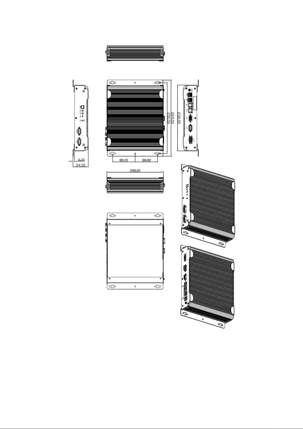
1.2 Dimensions…………………………………...……………….…………......7
1.3 Brief Description ……………….……..………………….………………8
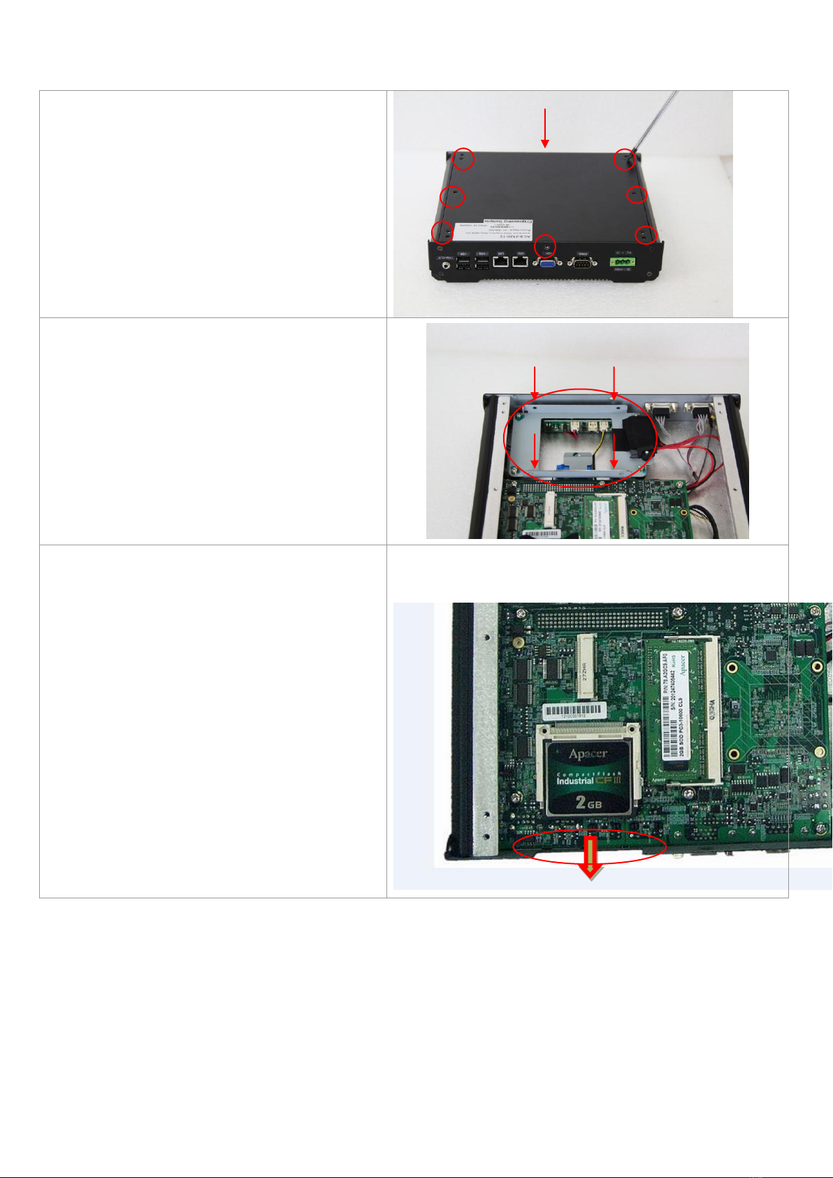
1.4 Installation of HDD & CF.........................................................................9
Chapter 2 Hardware Installation
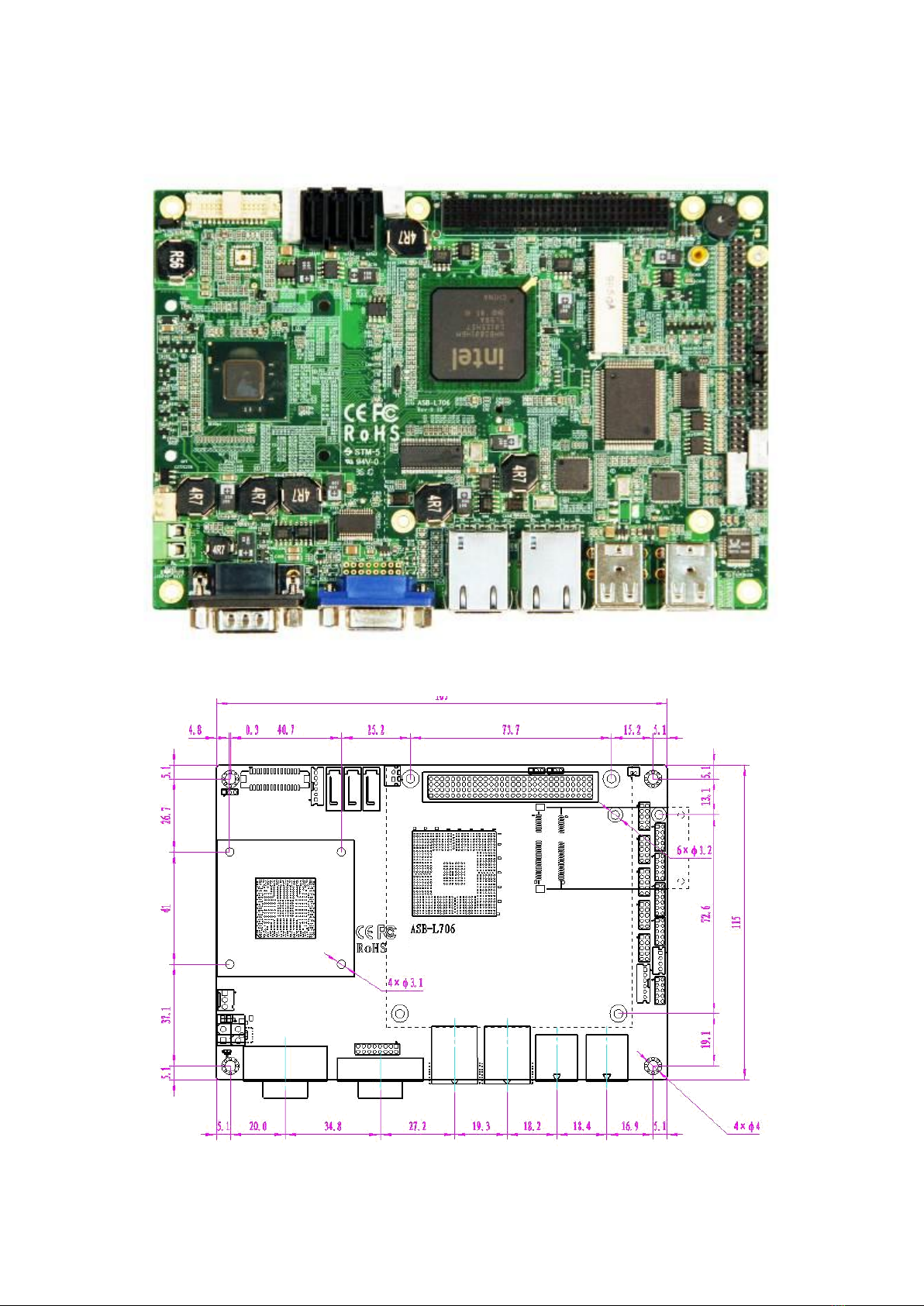
2.1 Mainboard Specifications………………………..…………….…………10
2.2 Jumpers Setting and Connectors………………………….……………14
Chapter 3 BIOS Setup
3.1 Operations after POST Screen.............................................................23
3.2 BIOS SETUP UTILITY................................................................24
3.3 System Overview.......................................................................25
3.4 Advanced Settings................................................................... 26
3.5 Advanced PCI/PnP Settings................................................................ 34
3.6 Boot Settings....................................................................................... 37
3.7 Security Settings.................................................................................. 39
3.8 Advanced Chipset Settings.................................................................. 40
3.9 Exit Options..........................................................................................45
Chapter 4 Installation of Drivers
4.1 Intel Chipset Driver.…………………………...……………………………48
4.2 Intel GMA 3150 VGA Chipset Driver..…....…......……………….......…..51
4.3 Intel 82574L Network adapter Driver……..................................……….54

ACS-2120 User Manual
5
4.4 Realtek HD Audio Driver Installation………………….…………………57
Figures
Figure 1.1: Dimensions of the ACS-2120…..……..…………………………...7
Figure 1.2: Front View of ACS-2120..............................................................8
Figure 1.3: Rear View of ACS-2120..............................................................8
Figure 2.1: Mainboard Overview………………………………..……..………10
Figure 2.2: Mainboard Dimensions……………………………………………10
Figure 2.3: Jumpers and Connectors Location-TOP…………………...……11
Figure 2.4: Jumpers and Connectors Location- Bottom………………….…11

ACS-2120 User Manual
6
Chapter 1________________Getting Started
1.1 Specifications
Specs
ACS-2120
CPU
Intel Atom D525 1.8GHz Processor, FSB 800MHz
System Chipset
Intel ICH8M Chipset
System Memory
1 x 204 Pin SO-DIMM socket, support 800MHz up to 2GB SDRAM,
default 2GB
External I/O Port
Rear Side:
4 x USB 2.0 connectors
2 x RJ-45 LAN connectors
1 x DB-9 RS232 (COM 1)
1 x DB-15 VGA
1 x 3-Pin DC terminal block connector
1 x Audio line out
Front Side:
1 x RS-232 (COM2)
1 x RS-232/422/485 default RS-485 (COM3)
1 x Power switch
Expansion Slots
None
Storage
1 x 2.5" SATA HDD Space default 320GB
1 x CF internal slot
Power Supply
Default DC 12V /Optional 11~32V DC input
Construction / Color
Aluminum Heatsink + Steel Chassis
Mounting
Wall mount
Dimensions
232(W) x 200(H) x 48 (D)
269(W) x 200(H) x 54 (D) (wall mount)
Operating Temperature
-20 °C ~50 °C
Storage Temperature
-30 °C ~60 °C
Storage Humidity
10%~90%@ 40℃, non-condensing
Certificate
CE / FCC Class A

ACS-2120 User Manual
7
1.2 Dimensions
Figure 1.1: Dimensions of the ACS-2120

ACS-2120 User Manual
8
1.3 Brief Description of the ACS-2120
ACS-2120 is a Fan-less High-efficiency Thermal Solution and ultra-compact standalone Box PC,
powered by an Intel Atom D525 1.8GHz and supporting 4 x USB 2.0 ports, 3 x COM Ports, 1 x VGA,
support 1 x SATA HDD space, 1 x internal CF slot, 11~32V DC wide-ranging power input etc. It is
ideal for kiosks, POS systems, airport terminal controllers, digital entertainments, etc. and running
factory operations from small visual interface and maintenance applications to large control process
applications. ACS-2120 works very well along with any of our Display Monitor series and it absolutely
can provide an easy way to perform control and field maintenance.
Figure 1.2: Front View of ACS-2120
Figure 1.3: Rear View of ACS-2120

ACS-2120 User Manual
9
1.4 Installation of HDD & CF
Step 1
Gently remove 8 screws as shown in the
picture.
Step 2
There is a hard disk tray to put hard disk.
Gently remove the 4 screws in hard disk
tray to replace hard disk.
Step 3
There is a CF slot to replace CF.

ACS-2120 User Manual
10
Chapter 2__________Hardware Installation
2.1 Mainboard Specifications
Figure 2.1: Mainboard Overview
Figure 2.2: Mainboard Dimensions

ACS-2120 User Manual
11
Figure 2.3: Jumpers and Connectors Location-TOP
Figure 2.4: Jumpers and Connectors Location-Bottom

ACS-2120 User Manual
12
Specifications
Board Size
165mm x 115mm
CPU Support
Intel Atom D525 /1.80GHz (onboard)
Chipset
Intel Atom D525 + Intel ICH8M
Memory
Support
1x SO-DIMM (204pins), up to 2GB DDR3 800MHz FSB
Graphics
Integrated by D525 GMA 3150
Super I/O
Winbond W83627UHG
BIOS
AMIBIOS
Storage
3 x SATA Connector
1 x Compact Flash II Slot
Network
2 x RJ-45 1000Mbps LAN Intel 82574L
USB
4 x USB 2.0 stack port for external
2 x USB 2.0 internal Pin header
2 x USB 2.0 internal for mini PCIe
Serial
1 x RS232 port, DB9 connector for external (COM1),
pin 9 w/5V/12V/Ring select
1 x RS232/422/485 select header for internal (COM3), default
RS232
4 x RS232 header for internal (COM2,COM4,COM5,COM6)
Digital I/O
8-bit digital I/O by Pin header
4-bit digital Input
4-bit digital Output
Battery
Support CR2477 Li battery by 2-pin header
Audio
Support Audio via Realtek ALC662 HD audio decoder
Support Line-in, Line-out, MIC by 2x5-pin header
Keyboard
/Mouse
1x PS2 keyboard/mouse by 1x6 box pin header
Expansion Bus
1x PC 104+ connector (PCI master 4, jumper for +3.3V & 5V
select)
2x mini-PCI-express slot (1x full size, 1x half-size )
Power
Management
DC12V input
1 x 2-pin power input connector
Front I/O
by 2x5-pin header
Power on/off switch

ACS-2120 User Manual
13
Reset switch
Power LED status
HDD LED status
Buzzer
Watchdog
Timer
Software programmable 1 –255 second by Super I/O
External I/O
port
1 x COM Port (COM1)
4 x USB 2.0 Ports (stack)
2 x RJ45 GbE Ports (10/100/1000Mbps)
1 x VGA Port
1 x VGA 2x8 Pin Header
Temperature
Operating: 0℃–60℃
Storage: -20℃–80℃
Humidity
5% - 95%, non-condensing, operating
Power
Consumption
12V /1.6A (Intel D525 processor with 2GB DDR3 DRAM)
EMI/EMS
CE/FCC class A

ACS-2120 User Manual
14
2.2 Jumpers Setting and Connectors
1. JCLR_CMOS: (2.0mm Pitch 1x3 Pin Header)CMOS clear jumper, CMOS clear
operation will permanently reset old BIOS settings to factory defaults.
JCLR_CMOS
CMOS
CLOSE 1-2
NORMAL
(default)
CLOSE 2-3
Clear CMOS
Procedures of CMOS clear:
5.4.1.1 Turn off the system and unplug the power cord from the power outlet.
5.4.1.2 To clear the CMOS settings, use the jumper cap to close pins 2 and 3 for about
3 seconds then reinstall the jumper clip back to pins 1 and 2.
5.4.1.3 Power on the system again.
5.4.1.4 When entering the POST screen, press the <F1> or <DEL> key to enter CMOS
Setup Utility to load optimal defaults.
5.4.1.5 After the above operations, save changes and exit BIOS Setup.
2. JVCCIO: (2.0mm Pitch 1x3 Pin Header) PC104+ port voltage selection jumper,select
voltage for PCI-104 Plus device. The default for this jumper is “all open”, meaning
the user must select the voltage to be used.
JVCCIO
PC104+ VCCIO
Voltage
CLOSE 1-2
+3.3V
CLOSE 2-3
+5V
all Open
(Default)
3. BZ: onboard buzzer.
4. JCOM6: (2.0mm Pitch 1x3 Pin Header) COM6 setting jumper, pin 1~3 are used to
select signal out of pin 10 of COM6 port.
JP1 Pin#
Function
Close 1-2
COM6 Pin10=+5V (default)
Close 2-3
COM6 Pin10=+12V (option)
5. JP2: (2.0mm Pitch 1X2 Pin Header), ATX Power and Power auto on setting jumper.
JP2
Mode
Open
ATX Power Mode

ACS-2120 User Manual
15
Close
Power Auto on (Default)
6. BAT: (1.25mm Pitch 1x2 box Pin Header) 3.0V Li battery is embedded to provide
power for CMOS.
Pin#
Signal
Name
Pin1
VBAT
PIN2
Ground
7. F_PANEL: (2.0mm Pitch 2X5 Pin Header), Front panel connector.
Signal Name
Pin#
Pin#
Signal Name
HD LED+
1
2
POWER
LED+
HD LED-
3
4
POWER LED-
Ground
5
6
PWRBTN
RESET
7
8
Ground
BUZZER+
9
10
BUZZER-
Pin1-3: HDD LED, They are used to connect hard disk activity LED. The LED blinks
when the hard disk is reading or writing data.
Pin2-4: POWER LED, They are used to connect power LED. When the system is
powered on or under S0/S1 state, the LED is normally on; when the
system is under S4/S5 state, the LED is off.
Pin5-6: POWER on/off Button, They are used to connect power switch button.
The two pins are disconnected under normal condition. You may short
them temporarily to realize system startup & shutdown or awaken the
system from sleep state.
Pin7-8: RESET Button, They are used to connect reset button. The two pins are
dis-
connected under normal condition. You may short them temporarily to
realize
system reset.
Pin9-10: BUZZER, They are used to connect an external buzzer.
Note:
When connecting LEDs and buzzer, pay special attention to the signal
pola-
rity. Make sure that the connector pins have a one-to-one correspondence
with chassis wiring, or it may cause boot up failure.

ACS-2120 User Manual
16
8. USB3: (2.0mm Pitch 2x5 Pin Header) ,Front USB connector, it provides two USB
ports via a dedicated USB cable, speed up to 480Mb/s.
Signal Name
Pin#
Pin#
Signal Name
+5V
1
2
+5V
USB_P6_DN
3
4
USB_P7_DN
USB_P6_DP
5
6
USB_P7_DP
Ground
7
8
Ground
NC
9
10
Ground
Note:
Before connection, make sure that pinout of the USB Cable is in accordance with that
of the said tables. Any inconformity may cause system down and even hardware
damages.
9. JCOM: (2.0mm Pitch 2x6 Pin Header) COM1 and COM3 setting jumper, pin 1~6 are
used to select signal out of pin 9 of COM1 port; pin 7~12 are used to select output type
for COM3 port (RS232 Type or RS422 Type or RS485 Type).
JCOM Pin#
Function
CLOSE 1-2
COM1 Pin9=RI (default)
CLOSE 3-4
COM1 Pin9=+5V (option)
CLOSE 5-6
COM1 Pin9=+12V (option)
CLOSE 7-9
COM3 FOR RS232 FROM COM3
(default)
CLOSE 8-10
COM3 FOR RS485 FROM COM33
(option)
CLOSE 10-12
COM3 FOR RS422 FROM COM33
(option)
Note:
Since COM3 and COM33 use the same address, they cannot work at the same time.
10. GPIO: (2.0mm Pitch 2x5 Pin Header),General-purpose input/output port, it provides
a group of self-programming interfaces to customers for flexible use.

ACS-2120 User Manual
17
Signal Name
Pin#
Pin#
Signal Name
GPIO20
1
2
GPIO60
GPIO21
3
4
GPIO61
GPIO22
5
6
GPIO62
GPIO23
7
8
GPIO63
Ground
9
10
+5V
11. COM33:(2.0mm Pitch 1x4 box Pin Header),it provides selectable RS422/RS485
serial signal output.
RS422 Type (option)
RS485 Type (option)
Signal Name
Pin#
Pin#
Signal Name
422RXD-
1
1
NC
422RXD+
2
2
NC
422TXD-
3
3
485B-
422TXD+
4
4
485A+
Note:
Use COM3 RS232/RS485 Function, please setting JCOM Jumpers and BIOS CMOS
Setup.
Path:
BIOS Setup Utility \ Advanced Setting \ SuperIO Configuration \ Serial Port3
Type:
[RS232
Type]
[RS485
Type]
12. F_AUDIO: (2.0mm Pitch 2x5 Pin Header), Front Audio, An onboard Realtek
ALC662 codec is used to provide high-quality audio I/O ports. Line Out can be
connected to a headphone or amplifier. Line In is used for the connection of external
audio source via a Line in cable. MIC is the port for microphone input audio.
Signal Name
Pin#
Pin#
Signal Name
FRONT-OUT-L
1
2
LINEIN_R
AUD_AGND
3
4
AUD_AGND
FRONT-OUT-
R
5
6
LINEIN_L
AUD_AGND
7
8
AUD_AGND
FRONT-MIC1
9
10
FRONT-MIC

ACS-2120 User Manual
18
2
13. COM2-COM6:(2.0mm Pitch 2x5 Pin Header),COM2 COM3 COM4 COM5 COM6
Ports, up to 5 standard RS232 ports are provided. They can be used directly via COM
cable connection.
COM2,COM3,COM4,COM5 Signal Name:
Signal
Name
Pin#
Pin#
Signal Name
DCD
1
2
RXD
TXD
3
4
DTR
Ground
5
6
DSR
RTS
7
8
CTS
RI
9
10
NC
COM6 Signal Name:
Signal
Name
Pin#
Pin#
Signal Name
DCD
1
2
RXD
TXD
3
4
DTR
Ground
5
6
DSR
RTS
7
8
CTS
RI
9
10
JCOM6 Setting:
Pin1-2 : 5V
(Default)
Pin2-3:12V
(option)
Note:
COM3 port is controlled by pins No.7~10 of JCOM. For details, please refer to descrip-
tion of JCOM and COM33 BIOS Setup.
14. KB/MS: (2.0mm Pitch 1x6 box Pin Header), PS/2 keyboard and mouse port, the
port can be connected to PS/2 keyboard or mouse via a dedicated cable for direct
used.
Pin#
Signal
Name
1
KBDATA
2
MSDATA

ACS-2120 User Manual
19
3
Ground
4
+5V
5
KBCLK
6
MSCLK
15. USB1/2:(Double stack USB type A), Rear USB connector, it provides up to 4
USB2.0 ports, speed up to 480Mb/s.
Each USB Type A Receptacle (2 Ports) Current limited value is 1.5A.
If the external USB device current exceeds 1.5A, please separate connectors
into different Receptacle.
16. LAN1/2: (RJ45 Connector), Rear LAN port,2 standard 10/100/1000M RJ-45 Ethernet
ports are provided. Used Intel 82567LM chipset ,LINK LED (green) and ACTIVE LED
(yellow) respectively located at the left-hand and right-hand side of the Ethernet port
indicate the activity and transmission state of LAN.
17. VGA: (CRT Connector DB15),Video GraphicArray Port, provide high-quality video
output. they can not work at the same time for VGA and VGA-PH.
18. VGA-PH: (CRT 2.0mm Pitch 2x8 Pin Header), Video Graphic Array Port, Provide
2x8 Pin cable to VGAPort, they can not work at the same time for VGA and
VGA-PH.
Signal Name
Pin#
Pin#
Signal Name
CRT_RED
1
2
Ground

ACS-2120 User Manual
20
CRT_GREEN
3
4
Ground
CRT_BLUE
5
6
NC
CRT_R_HSYN
C
7
8
CRT_PU_DDC_DAT
CRT_R_VSYN
C
9
10
CRT_PU_DDC_CLK
NC
11
12
NC
+12V
13
14
Ground
+12V
15
16
Ground
19. CPU SCREW HOLES: Four screw holes for fixed CPU Cooler assemble.
20. COM1: (Type DB9),Rear serial port, standard DB9 serial port is provided to make
a direct connection to serial devices. COM1 port is controlled by pins No.1~6 of
JCOM,select output Signal RI or 5V or 12v, For details, please refer to description of
JCOM.
21. AT12V: (5.0mm 1x2 Pin Connector),DC12V System power input connector。
Pin#
Signal Name
1
+12V
2
Ground
Note:
Make sure that the voltage of power supply is DC(12±5%)V before power on, or
it may cause boot up failure and even system damage.
22. FAN: (2.54mm Pitch 1x3 Pin Header),Fan connector, cooling fans can be
connected directly for use. You may set the rotation condition of cooling fan in menu of
BIOS CMOS Setup.
Pin#
Signal Name
1
Ground
2
VCC
3
Rotation
Table of contents
Other Aplex Desktop manuals

Aplex
Aplex ACS-2320 User manual

Aplex
Aplex ACS-2170 User manual

Aplex
Aplex VIPAC-915 P User manual

Aplex
Aplex ACS-2685 User manual

Aplex
Aplex ACS-2210A User manual

Aplex
Aplex AHM-6159P User manual

Aplex
Aplex ARMPAC-6 Series User manual

Aplex
Aplex ACS-2110 User manual

Aplex
Aplex ACS-2630 User manual

Aplex
Aplex ACS-2310 User manual

Aplex
Aplex ACS-2180 User manual

Aplex
Aplex ACS-2645 User manual

Aplex
Aplex ACS-2695A User manual

Aplex
Aplex ACS-2675C Box PC User manual

Aplex
Aplex ACS-2310 User manual

Aplex
Aplex APC-3X95P_R User manual

Aplex
Aplex APC-3784A/85A User manual

Aplex
Aplex APC-3X18 User manual

Aplex
Aplex ACS-2695 User manual

Aplex
Aplex ViTAM-915P User manual