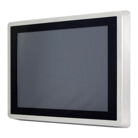
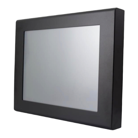
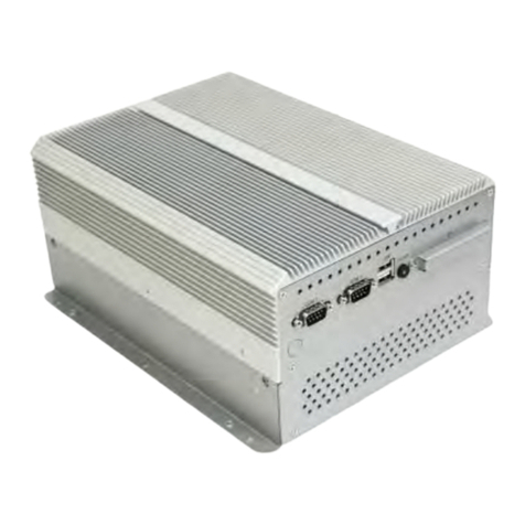
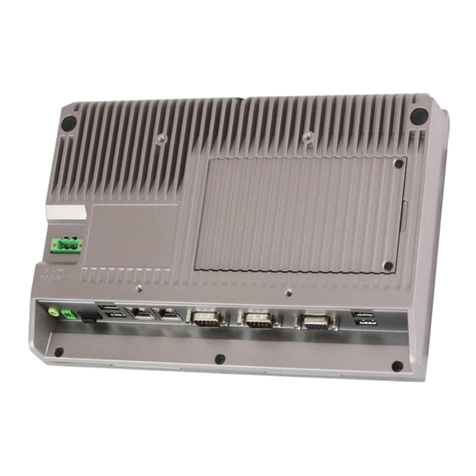
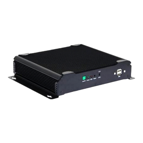
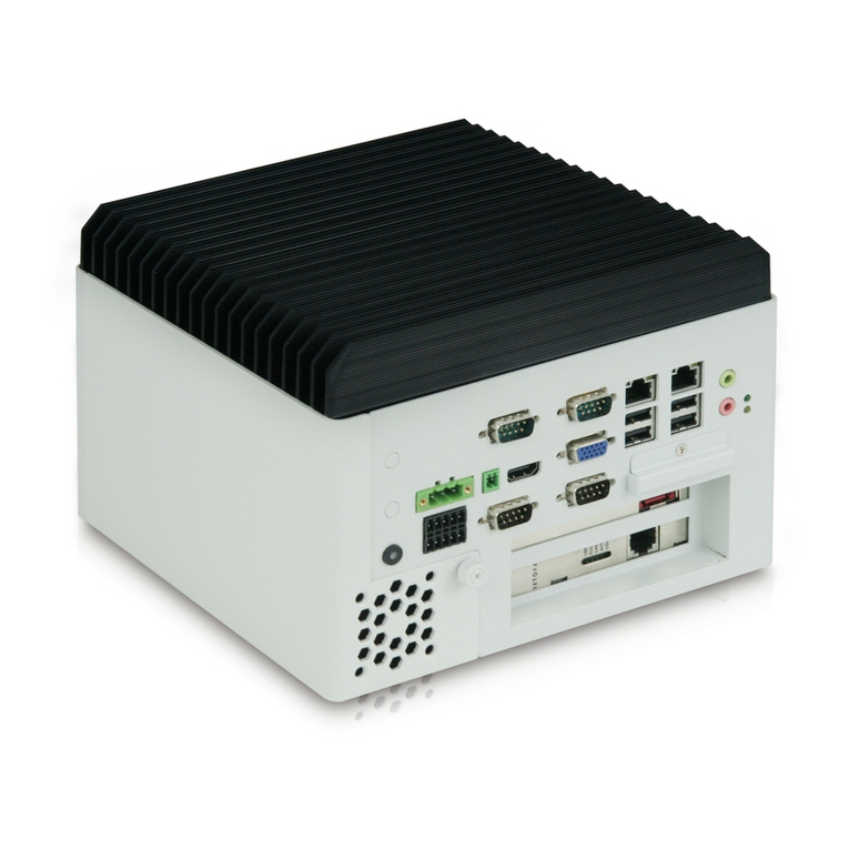
Aplex APC-3X18 User manual

APC-3X18 User Manual
1
APC-3X18
Panel PC User Manual
Release Date _ Revision
Oct. 2012 V1.0
® 2012 Aplex Technology, Inc. All Rights Reserved. Published in Taiwan
Aplex Technology, Inc.
15F-1, No.186, Jian Yi Road, Zhonghe District, New Taipei City 235, Taiwan

APC-3X18 User Manual
2
Warning!___________________________________
This equipment generates, uses and can radiate radio frequency energy and if not installed and
used in accordance with the instructions manual, it may cause interference to radio communications.
It has been tested and found to comply with the limits for a ClassA computing device pursuant to
FCC Rules, which are designed to provide reasonable protection against such interference when
operated in a commercial environment. Operation of this equipment in a residential area is likely
to cause interference in which case the user at his own expense will be required to take whatever
measures may be required to correct the interference.
Disclaimer
This information in this document is subject to change without notice. In no event shall Aplex
Technology Inc. be liable for damages of any kind, whether incidental or consequential, arising
from either the use or misuse of information in this document or in any related materials.
Electric Shock Hazard –Do not operate the machine with its back cover removed. There are
dangerous high voltages inside.

APC-3X18 User Manual
3
Packing List
Accessories (as ticked) included in this package are:
□AC power cable
□Driver & manual CD disc
□Other.___________________(please specify)
Safety Precautions
Follow the messages below to prevent your systems from damage:
◆Avoid your system from static electricity on all occasions.
◆Prevent electric shock. Don‘t touch any components of this card when the card is
power-on. Always disconnect power when the system is not in use.
◆Disconnect power when you change any hardware devices. For instance, when you
connect a jumper or install any cards, a surge of power may damage the electronic
components or the whole system.

APC-3X18 User Manual
4
Table of Contents______________________
Warning!…………………………………………………………………………….……..….2
Disclaimer………………………………………………………………….…………………2
Packing List…………………………………………………………………………………..3
Safety Precautions…………………………………………………………………………..3
Chapter 1 Getting Started
1.1 Specifications……………………………………..….……………………..6
1.2 Dimensions………………………………...………………………….......8
1.3 Installation of HDD………………….…………………………….……….12
1.4 Installation of PCI Add-on………..……………………………………..14
1.5 Brief Description…………………………………………………….……15
1.6 Panel Mounting…………………………………………………………..16
Chapter 2 Hardware
2.1 Mainboard………………..…….……………………………………..…..17
2.2 Installations…….…………………………………….…………………...18
2.2.1 Jumpers Setting and Connectors……...………..………………….....18
Chapter 3 BIOS Setup
3.1 Operations after POST Screen.............................................................36
3.2 BIOS SETUP UTILITY..........................................................................37
3.3 System Overview..................................................................................37
3.4 Advanced Settings............................................................................... 38
3.5 Advanced PCI/PnP Settings................................................................ 47
3.6 Boot Settings....................................................................................... 50
3.7 Security Settings.................................................................................. 52
3.8 Advanced Chipset Settings.................................................................. 53
3.9 Exit Options..........................................................................................60
Chapter 4 Installation of Drivers
4.1 Intel Chipset Driver.…………………………...…………………………63
4.2 Intel Graphics Media Accelerator Driver...……………………………..66
4.3 Intel 82574L LAN Device Driver………………………………………….70
4.4 Realtek ALC662 HD Audio Driver Installation…….………….…………73
4.5 Microsoft .NET Framework 3.5 Service Installation……………………75

APC-3X18 User Manual
5
Chapter 5 Touch Screen Installation
5.1 Introduction to Controller Board..…………………………..……………78
5.2 Windows 2000/XP USB Driver Installation for 5000 Boards………..….78
Figures
Figure 1.1: APC-3218 Dimensions……………………………………..…....8
Figure 1.2: APC-3518 Dimensions……………………………………..…....9
Figure 1.3: APC-3718 Dimensions……………………………………..…....10
Figure 1.4: APC-3918 Dimensions………………………………………….11
Figure 1.5: Front View………………………………………………………...15
Figure 1.6: Rear View………………………………………………………..15
Figure 1.7: Panel mounting…………………………………………………..16
Figure 1.8: VESA mounting…………………………………………………..16
Figure 2.1: Mainboard Dimensions…………………………………..…….....17
Figure 2.2: Jumpers and Connectors Location_ Board Top………………...18
Figure 2.3: Jumpers and Connectors Location_ Board Bottom…………....19
Figure 5.1 Birdeye’s View of Control Board…………………………………78
APC-3X18 User Manual
6
Chapter 1 System
1.1 Specifications
Specs
APC-3218
APC-3518
APC-3718
APC-3918
Processor
Intel Socket P Core 2 Duo Processor FSB 667/800/1066 MHz, up to Intel T9400
2.53GHz
System Chipset
Intel GM45 + ICH9M-E
System Memory
2 x 204 Pin DDR3 SO-DIMM, up to 8 GB SDRAM
Outside I/O port
4 x USB 2.0 connectors
2 x GbE LAN connectors
1 x VGA
2 x RS-232 (COM1/2)
1 x terminal block for additional power switch
2 x LED light for power and HDD indication
1 x Audio line out/ MIC in
1 x DB-9 RS-422/485, default RS-485 (COM3) for option
1 x 8 Pin terminal block connector for VCC/Ground/6XGPIO
1 x USB 2.0 connector with cap at front panel
1 x 3 Pin DC Power input terminal block
Storage
2 x 2.5” SATA HDD (one HDD as standard, two HDDs as option for RAID)
1 x External CF Slot for option
Extension
1 x PCI for option
OSD Control
Brightness/ Screen and Touch on/off /Power on/off
CD/DVD-R Device
1 x Slim CD/DVD RW Device for option (Not available if 2 HDD and CF have been used)
Wireless LAN
mini-PCIe interface for option
Web CAM
Web CAM USB Device for option
Auto Brightness
Auto Dimming for option
Speaker
2 x 2W Speaker for option
OS Support
Windows XP Professional, XP Embedded, Windows Embedded Standard 7, Windows 7
Pro for Embedded
Display Size
12.1”
800x600
15”
1024x768
17”
1280x1024
19”
1280x1024
Maximum Colors
262K
262K
16.7M
16.2M
Viewing Angle
(Degree)
H:140 / V:110
H:160 / V:145
H:170 / V:160
H:170 / V:160
Luminance (cd/m²)
350
400
350
350
Backlight Lifetime
50,000 Hours

APC-3X18 User Manual
7
Touch Screen Type
Resistive Touch Screen (option)
Light Transmission
80%
Power Supply
9~32V DC
Construction
Aluminum front bezel and steel chassis
IP Rating
Front Panel IP65
Mounting
Panel / VESA 75x75 Mount
Panel / VESA
100x100 Mount
Dimensions
(WxHxD)
390x264x91.5
410x310x89.4
439x348x97.3
484x400x83
Net Weight
7.6kgs
8.1kgs
11.1kgs
11.8kgs
Operating
Temperature
-10~50℃
Storage
Temperature
-20~60℃
Relative Humidity
10%~90%@ 40℃, non-condensing
Certificate
CE / FCC Class A

APC-3X18 User Manual
8
1.2 Dimensions
F i g u r e 1 . 1 : D i m e n s i o n s o f t h e A P C - 3 218
Warning!…………………………………………………………………………….……..….2
Disclaimer………………………………………………………………….…………………2
Packing List…………………………………………………………………………………..3
Safety Precautions…………………………………………………………………………..3
Chapter 1 Getting Started
1.1 Specifications……………………………………..….……………………..6
1.2 Dimensions………………………………...………………………….......8
1.3 Installation of HDD………………….…………………………….……….12
1.4 Installation of PCI Add-on………..……………………………………..14
1.5 Brief Description…………………………………………………….……15
1.6 Panel Mounting…………………………………………………………..16
Chapter 2 Hardware
2.1 Mainboard………………..…….……………………………………..…..17

APC-3X18 User Manual
9
2.2 Installations…….…………………………………….…………………...18
2.2.1 Jumpers Setting and Connectors……...………..………………….....18
Chapter 3 BIOS Setup
3.1 Operations after POST Screen.............................................................36
3.2 BIOS SETUP UTILITY..........................................................................37
3.3 System Overview..................................................................................37
3.4 Advanced Settings............................................................................... 38
3.5 Advanced PCI/PnP Settings................................................................ 47
3.6 Boot Settings....................................................................................... 50
3.7 Security Settings.................................................................................. 52
3.8 Advanced Chipset Settings.................................................................. 53
3.9 Exit Options..........................................................................................60
Chapter 4 Installation of Drivers
4.1 Intel Chipset Driver.…………………………...…………………………63
4.2 Intel Graphics Media Accelerator Driver...……………………………..66
4.3 Intel 82574L LAN Device Driver………………………………………….70
4.4 Realtek ALC662 HD Audio Driver Installation…….………….…………73
4.5 Microsoft .NET Framework 3.5 Service Installation……………………75
Chapter 5 Touch Screen Installation
5.1 Introduction to Controller Board..…………………………..……………78
5.2 Windows 2000/XP USB Driver Installation for 5000 Boards………..….78
Figures
Figure 1.1: APC-3218 Dimensions……………………………………..…....8
Figure 1.2: APC-3518 Dimensions……………………………………..…....9
Figure 1.3: APC-3718 Dimensions……………………………………..…....10
Figure 1.4: APC-3918 Dimensions………………………………………….11
Figure 1.5: Front View………………………………………………………...15
Figure 1.6: Rear View………………………………………………………..15
Figure 1.7: Panel mounting…………………………………………………..16
Figure 1.8: VESA mounting…………………………………………………..16
Figure 2.1: Mainboard Dimensions…………………………………..…….....17
Figure 2.2: Jumpers and Connectors Location_ Board Top………………...18
Figure 2.3: Jumpers and Connectors Location_ Board Bottom…………....19
Figure 5.1 Birdeye’s View of Control Board…………………………………78
APC-3X18 User Manual
10
Figure 1.2: Dimensions of the APC-3518

APC-3X18 User Manual
11
Figure 1.3: Dimensions of the APC-3718

APC-3X18 User Manual
12
Figure 1.4: Dimensions of the APC-3918

APC-3X18 User Manual
13
1.3 Installation of HDD
Step 1
There are 2 screws to deal with when
enclosing or removing the HDD bracket.
Step 2
There is 1 screw to deal with when
enclosing or removing the HDD Tray.
Step 3
Loosen screw and draw the HDD bracket
out as shown in the picture

APC-3X18 User Manual
14
Step 4
Tighten four screws as shown in the picture.
F Screw M3*5L 120°
Step 5
Push into the HDD bracket as shown in the
picture
Step 5
That’s how it should look after it has been
installed.

APC-3X18 User Manual
15
1.4 Installation of PCI Add-on
Step 3
To finish the job, just fasten the 2 screws as
shown in the picture.
Step 1
There are 2 screws to deal with when
enclosing or removing the chassis.
Step 2
Now slide the add on into the PCI slot, making
sure the golden part faces the slot. When the
part that is interfaced together come into the
right contact, slightly push the add on into the
rail of the slot.
After sliding the add on into the PCI expansion
slot, get the one screw as circled tightened to
finish the connection.

APC-3X18 User Manual
16
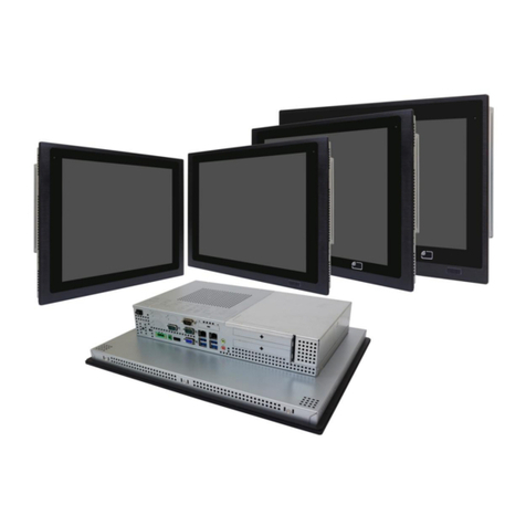
1.5 Brief Description of the APC-3X18
The APC-3218/3518/3718/3918 is Intel Socket P Core 2 Duo Intel GM45+ ICH9M-E Steel Panel PC,
which comes with a 12.1-inch (luminance of 350 cd/m²)/15-inch (luminance of 400 cd/m²)/17-inch
(luminance of 350 cd/m²)/19-inch (luminance of 350 cd/m²) TFT LCD. It is powered by an Intel Socket
P Core 2 Duo Processor, up to Intel P8600 2.4GHz processor. The industrial panel PC also features
one PCI expansion slot for option, three COM ports, four USB 2.0 ports, two 2.5” HDD, one external
CF slot for option, and 9~32V DC, etc. It is ideal for use as a PC-based controller for Automotive,
Logistic Process, Materials Handling, and Kiosk applications.
Figure 1.5: Front View of APC-3X18
Figure 1.6: Rear View of APC-3X18

APC-3X18 User Manual
17
1.6 Panel Mounting of the APC-3218/3518/3718/3918
The APC-3218/3518/3718/3918 panel PC is designed to be panel-mounted as shown in Figure 1.7.
Just carefully place the unit through the hole and tighten the given 10 screws from the rear to secure
the mounting.
Figure 1.7: Panel mounting of the APC-3218/3518/3718/3918
Figure 1.8: VESA mounting of the APC-3218/3518/3718/3918

APC-3X18 User Manual
18
Chapter 2 Hardware
2.1 Mainboard
Figure 2.1: Mainboard Dimensions

APC-3X18 User Manual
19
2.2 Installations
ASB-M801 is a Mini-ITX industrial motherboard developed on the basis of Intel GM45 and
ICH9M, which provides abundant peripheral interfaces to meet the needs of different customers. Also,
it features dual 1000M LAN port, 6-COM port and one Mini PCIE configuration. To satisfy the special
needs of high-end customers, PC104+ port (capable of adjusting IO voltage) richer extension
functions. The product is widely used in various sectors of industrial control.
2.2.1 Jumpers Setting and Connectors
Figure 2.2: Jumpers and Connectors Location_ Board Top

APC-3X18 User Manual
20
Figure 2.3: Jumpers and Connectors Location_ Board Bottom
1. JP2:
(2.0mm Pitch 1X2 Pin Header),ATX Power and Auto Power on jumper setting.
JP2
Mode
Open
ATX Power
Close
Auto Power on
(Default)
2. RTC/SRTC:
(2.0mm Pitch 1X2 Pin Header)CMOS clear jumper, CMOS clear operation will
permanently reset old BIOS settings to factory defaults.
RTC/SRTC
CMOS
Table of contents
Other Aplex Desktop manuals

Aplex
Aplex ACS-2310 User manual

Aplex
Aplex ACS-2210A User manual

Aplex
Aplex ACS-2180 User manual

Aplex
Aplex ACS-2310 User manual

Aplex
Aplex APC-3X95P_R User manual

Aplex
Aplex AHM-6159P User manual

Aplex
Aplex ACS-2695A User manual

Aplex
Aplex ACS-2110 User manual

Aplex
Aplex APC-3784A/85A User manual

Aplex
Aplex ACS-2120 User manual

Aplex
Aplex ViTAM-915P User manual

Aplex
Aplex ACS-2675C Box PC User manual

Aplex
Aplex ARMPAC-6 Series User manual

Aplex
Aplex ACS-2170 User manual

Aplex
Aplex ACS-2695 User manual

Aplex
Aplex APC-3514 User manual

Aplex
Aplex ACS-2685 User manual

Aplex
Aplex ACS-2630 User manual

Aplex
Aplex VIPAC-915 P User manual

Aplex
Aplex ACS-2645 User manual