manuals.online logo
Brands
  1. Home
  2. •
  3. Brands
  4. •
  5. Apollo
  6. •
  7. Security Sensor
  8. •
  9. Apollo 55000-268 User manual

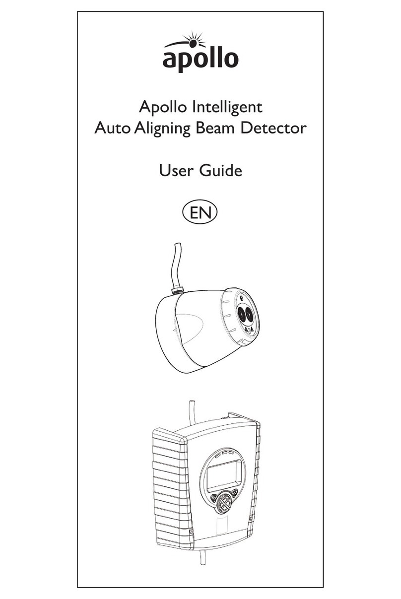
Apollo 55000-268 User manual

© Apollo Fire Detectors Limited 2005-2008
0786
FUNCTION
The intelligent reflective beam detector is a compact
detector for detecting smoke in large open areas such
as atria, warehouses, theatres and churches. It also
has a built-in 20D negative bi-directional short circuit
isolator.
The transmitter and receiver form a single unit
mounted to a wall of the building. A reflector which
returns the IR beam from the transmitter to the
receiver is mounted on the opposite wall. In the event
of smoke partially obscuring the light an imbalance
between the transmitted and received light will occur.
On interrogation by the control panel the detector will
then transmit an alarm value.
The intelligent reflective beam detector is an addition
to the Apollo range and not a replacement for the
XP95 loop-powered beam detector.
FEATURES
The intelligent reflective beam detector is supplied in
two versions: one for use at distances of 5–50m from
detector to reflector and the other for distances of
50–100m.
The detector is factory set to a beam obscuration of
35% which is the best setting for most factories and
warehouses. The setting can be changed to 25% for
offices and clean areas such as theatres or to 50% for
hostile areas such as mills or foundries.
The detector compensates automatically for gradual
contamination of the lenses in order to avoid false
alarms.
The detector is non-latching and resets 30 seconds
after an alarm event ceases and in 3 seconds after the
removal of a fault.
A termination backbox, part no 29600-241, is available.
This allows easy first fixing of the cabling and termina-
tions to the intelligent reflective beam detector. The
termination backbox can be surface or flush mounted.
PP2155/2008/Issue 3
INTELLIGENT REFLECTIVE
BEAM DETECTOR
Part nos 55000-268 (5–50m)
55000-273 (50–100m)
ELECTRICAL CONSIDERATIONS
The intelligent reflective beam detector is loop-
powered and requires no external power supply.
Each beam detector draws approximately 5mA
in quiescent and 9mA in alarm from the ana-
logue addressable loop and, unless proven by
calculation*, it is recommended that no more
than ten beam detectors be powered from each
loop.
*A loop voltage drop calculation program,
known as ‘Loop Calculator’, has been devel-
oped by Apollo for use by system designers
and is available as a free download from the
Apollo website (www.apollo-fire.co.uk)
LED FAULT INDICATION
A fault is indicated by the amber LED flashing
once a second.
If the drift compensation function has reached
its limit the amber LED flashes once every 2
seconds. The detector will continue to function
but maintenance procedures should be carried
out at the earliest opportunity.
PANEL COMPATIBILITY
Please note, not all control panels support this
beam detector. Please contact Apollo’s Technical
Sales department for further information.
FURTHER INFORMATION
The intelligent reflective beam detector must be
installed in accordance with the installation guide,
PP2146. This guide contains more information on
the following topics:
• system design
• installing beam detectors
• targeting, aligning and commissioning
the reflective beam detector
• troubleshooting
This guide is available on request or can be down-
loaded from the Apollo website,
www.apollo-fire.co.uk. If further assistance is
required, please contact the Technical Sales depart-
ment.
Technical Data
Supply Voltage 17–28V DC
(plus protocol)
Supply Current
Prism targeting mode 17mA
Alignment mode 17mA
Run mode (quiescent) 5mA
Alarm (LED illuminated) 9mA
Fault (LED illuminated) 5mA
Alarm thresholds
25% 2.50dB
35% 3.74dB
50% 6.02dB
Operating temperature –20°C to 55°C
Humidity 0 to 93%RH
(Non-Condensing)
IP rating 50
Material Flame Retardant ABS
Colour Grey/Black
Dimensions (beam detector)
Width 130mm
Height 210mm
Depth 120mm
Weight 670g
Dimensions (termination backbox)
Width 130mm
Height 190mm
Depth 50mm
Part no Description
45681-334 5–50 metres (detector to reflector)
45681-292 50–100 metres (detector to reflector)
45681-293 Termination backbox
For further technical information please refer to
PP2155-T, available on request.

Other manuals for 55000-268

1

This manual suits for next models

1

Other Apollo Security Sensor manuals

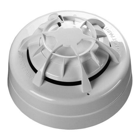
Apollo Smoke Detector XP95 Operating and safety instructions

Apollo

Apollo Smoke Detector XP95 Operating and safety instructions

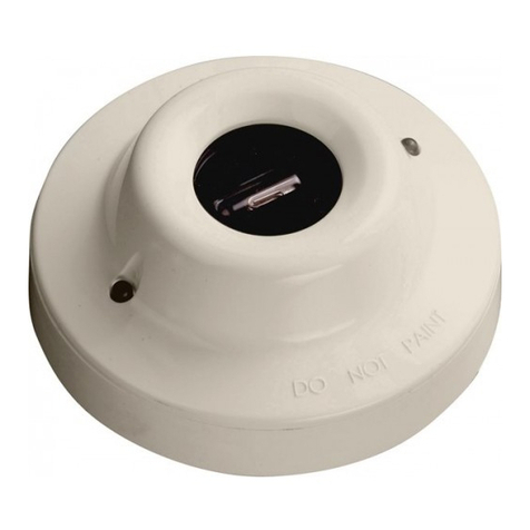
Apollo XPA-CB-11170-APO User manual

Apollo

Apollo XPA-CB-11170-APO User manual

Apollo ORB-OH-13001-APO User manual

Apollo

Apollo ORB-OH-13001-APO User manual

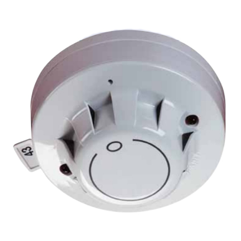
Apollo XP95A Series User manual

Apollo

Apollo XP95A Series User manual

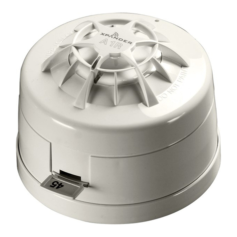
Apollo XPander User manual

Apollo

Apollo XPander User manual

Apollo Smoke Detector XP95 User manual

Apollo

Apollo Smoke Detector XP95 User manual

Apollo Discovery ASD-1 User manual

Apollo

Apollo Discovery ASD-1 User manual

Apollo XPander XPA-CB-12034-APO User manual

Apollo

Apollo XPander XPA-CB-12034-APO User manual

Apollo XP95 series User manual

Apollo

Apollo XP95 series User manual

Apollo 55000-268 User manual

Apollo

Apollo 55000-268 User manual

Apollo 65 Series User manual

Apollo

Apollo 65 Series User manual

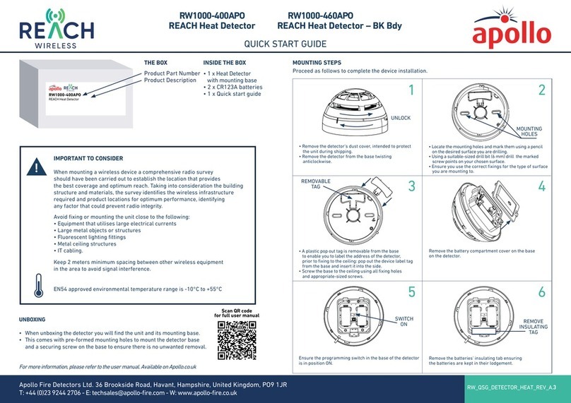
Apollo REACH RW1000-460APO User manual

Apollo

Apollo REACH RW1000-460APO User manual

Apollo SA7100-100APO User manual

Apollo

Apollo SA7100-100APO User manual

Apollo XP95A Series User manual

Apollo

Apollo XP95A Series User manual

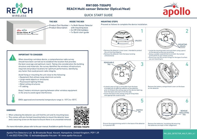
Apollo REACH WIRELESS RW1000-700APO User manual

Apollo

Apollo REACH WIRELESS RW1000-700APO User manual

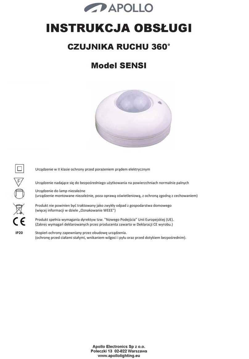
Apollo SENSI User manual

Apollo

Apollo SENSI User manual

Apollo XP95A Series User manual

Apollo

Apollo XP95A Series User manual

Apollo ORBIS ORB-OH-13003-APO User manual

Apollo

Apollo ORBIS ORB-OH-13003-APO User manual

Apollo 58000-300APO User manual

Apollo

Apollo 58000-300APO User manual

Apollo RoadRunner User manual

Apollo

Apollo RoadRunner User manual

Popular Security Sensor manuals by other brands

Sperry instruments VD7504GFI operating instructions

Sperry instruments

Sperry instruments VD7504GFI operating instructions

3M 8516 user guide

3M

3M 8516 user guide

Optex HX-40 installation instructions

Optex

Optex HX-40 installation instructions

GEV TITAN MOBI 180 manual

GEV

GEV TITAN MOBI 180 manual

Cardin Elettronica CDR Series manual

Cardin Elettronica

Cardin Elettronica CDR Series manual

Bosch FAP-420 Series Installation and operation

Bosch

Bosch FAP-420 Series Installation and operation

SKF TKSU 10 Instructions for use

SKF

SKF TKSU 10 Instructions for use

STEINEL PROFESSIONAL IR Quattro Slim XS LiveLink Information

STEINEL PROFESSIONAL

STEINEL PROFESSIONAL IR Quattro Slim XS LiveLink Information

Lince BABY WIRELESS GR868 Installation, operation and maintenance manual

Lince

Lince BABY WIRELESS GR868 Installation, operation and maintenance manual

JXCT JXBS-3001-SCY-PT2 manual

JXCT

JXCT JXBS-3001-SCY-PT2 manual

Forch 5380 16 1 manual

Forch

Forch 5380 16 1 manual

Bacharach Leakator Jr. Instruction

Bacharach

Bacharach Leakator Jr. Instruction

dehn PHEG1 FD Series Instructions for use

dehn

dehn PHEG1 FD Series Instructions for use

STEINEL iHF 3D manual

STEINEL

STEINEL iHF 3D manual

SafeGuard Compass user guide

SafeGuard

SafeGuard Compass user guide

GST DC-9101(Ex) quick start guide

GST

GST DC-9101(Ex) quick start guide

Airthings Wave Enhance AT-321 quick start guide

Airthings

Airthings Wave Enhance AT-321 quick start guide

Pilz PSEN opII3F Series operating manual

Pilz

Pilz PSEN opII3F Series operating manual

manuals.online logo
manuals.online logoBrands
  • About & Mission
  • Contact us
  • Privacy Policy
  • Terms and Conditions

Copyright 2025 Manuals.Online. All Rights Reserved.