manuals.online logo
Brands
  1. Home
  2. •
  3. Brands
  4. •
  5. Apollo
  6. •
  7. Security Sensor
  8. •
  9. Apollo XP95A Series User manual

Apollo XP95A Series User manual

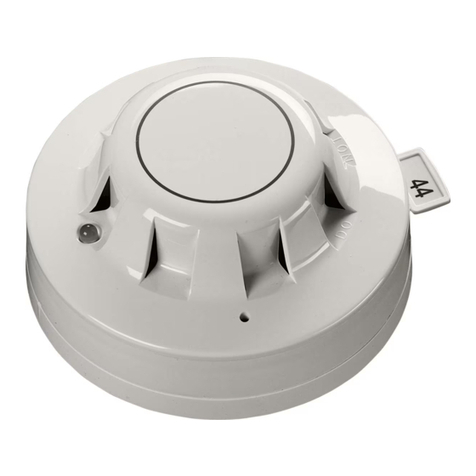
XP95A and Discovery Smoke & Heat Detectors
Installation Instructions
General
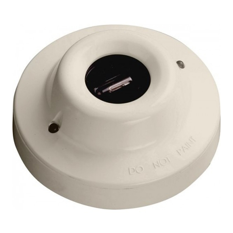
These instructions apply to Apollo detector base 45681-210, to variants of this base and to
the associated ranges of UL listed XP95A and Discovery detectors which are listed overleaf.
Installation
These products must be installed in accordance with the applicable NFPA standards, local
codes and jurisdictional authorities. Failure to follow these instructions may result in failure
of the detectors to report an alarm condition. Apollo Fire Detectors Limited is not responsi-
ble for detectors which are improperly installed, maintained and tested.
The FM approval for these initiating devices does not include or imply approval of the
control unit to which it may be connected. In order to maintain an FM approved system,
these initiating devices must be listed with an FM approved compatible control panel. For
more information on RTI classification refer to FM class standard 3210.
Before installing these products check the continuity, polarity and insulation resistance of all
wiring. Check that installation is in accordance with the fire system drawings and conforms
to all applicable local codes such as NFPA 72.
Use 3" octagonal box for direct connection to the base. 4" octagonal and 4" square boxes
may be used with proper UL listed mounting brackets. When mounting on a wall, install 4" to
12" from the ceiling. Use 3M Weatherban 606 Non-Flammable sealing compound (or equiv-
alent) to seal field wiring conduit opening in the electrical box, this will reduce the stack
effect. Secure the base to the electrical box with appropriate screws. Do not overtighten
the screws. The raised mark on the side of the base indicates the direction of the detec-
tor LED when fitted. Connect the shield, if required, to the SHIELD terminal on the base. For
information on how to set the address of each device correctly refer to the section 'Address
Setting' overleaf.
39214-035/Issue 11
Technical Data XP95A
Technical Data Discovery
14
Detector Model No. 55000-450 55000-550/555* 55000-650 55000-886
Detector Type Heat Ionization Photoelectric Multisensor
Working Voltage 17-28V dc 17-28V dc 17-28V dc 17-28V dc
Modulation Voltage
(V peak to peak) 5-9V 5-9V 5-9V 5-9V
Maximum Alarm
Current LED on 2.5mA 2.5mA 4.5mA 3.5mA
Surge Current 1.0 mA 1.0mA 1.0 mA 1.0mA
Supervisory Current 250μA280μA340μA500μA
Heat Element Rating 131ºF (55ºC) N/A N/A N/A
Compatibility Identifier 55000-450 55000-550/555* 55000-650 55000-886
Test Method •Hair dryer •Home safeguard
•Gemini 501
•Home safeguard
•Gemini 501
•Home safeguard
•Gemini 501
Control Panel Refer to: www.apollo-fire.co.uk for compatible panels.
*Please note 55000-555 is ULC listed only.
Detector Model No. 58000-450 58000-550 58000-650 58000-750
Detector Type Heat Ionization Photoelectric Multisensor
Working Voltage 17-28V dc 17-28V dc 17-28V dc 17-28V dc
Modulation Voltage
(V peak to peak) 5-9V dc 5-9V dc 5-9V dc 5-9V dc
Maximum Alarm
Current LED on 3.5mA 3.5mA 3.5mA 3.5mA
Surge Current 1.0 mA 1.0mA 1.0mA 1.0mA
Supervisory Current 500μA400μA500μA500μA
Heat Element Rating 135ºF (57ºC)
-210ºF (99ºC)
N/A N/A 135ºF (57ºC)
(Mode 5)
Compatibility Identifier 58000-450 58000-550 58000-650 58000-750
Test Method •Hair dryer •Home safeguard
•Sensitivity test
•No Climb
•Gemini 501
•Home safeguard
•Sensitivity test
•No Climb
•Gemini 501
•Home safeguard
•Sensitivity test
•No Climb
•Gemini 501
•Hair dryer (heat
sensor only)
Control Panel Refer to: www.apollo-fire.co-uk for compatible panels.
©Apollo Fire Detectors Ltd 2017
Apollo Fire Detectors Ltd, 36 Brookside Road, Havant, Hants, PO9 1JR, UK
Tel +44 (0)23 9249 2412 Fax +44 (0)23 9249 2754
Email: techsales@apollo-fire.com Website: www.apollo-fire.co.uk
In the USA: Apollo America Inc., 25 Corporate Drive, Auburn Hills, Michigan, 48326, USA
Tel: (248) 332-3900 Fax: (248) 692-0888
Email: info.us@apollo-fire.com Website: www.apollo-fire.com
Wiring
CAUTION: Do not use looped wire under wiring terminals. Break wire run to provide supervi-
sion of connections. Terminals L1 and L2 are polarity insensitive.
+
–
From control panel
L2
L1
R+
R–
L2
L1
R+
R–
L2
L1
R+
R–
EARTHEARTHEARTH
+
–
From control panel
L2
L1
R+
R–
L2
L1
R+
R–
L2
L1
R+
R–
EARTHEARTHEARTH
ττττ ττ
ττττ ττ
Fig. 1- Wiring diagram of XP95A/Discovery loop with single remote indicator
Fig. 2- Wiring diagram of XP95A/Discovery loop with common remote indicator
1
2
4
8
16
32
64
1
1
1
2
4
8
16
32
64
10
10
1
2
4
8
16
32
64
9
9
1
2
4
8
16
32
64
8
8
1
2
4
8
16
32
64
7
7
1
2
4
8
16
32
64
6
6
1
2
4
8
16
32
64
5
5
1
2
4
8
16
32
64
4
4
1
2
4
8
16
32
64
3
3
1
2
4
8
16
32
64
2
2
1
2
4
8
16
32
64
11
11
1
2
4
8
16
32
64
20
20
1
2
4
8
16
32
64
19
19
1
2
4
8
16
32
64
18
18
1
2
4
8
16
32
64
17
17
1
2
4
8
16
32
64
16
16
1
2
4
8
16
32
64
15
15
1
2
4
8
16
32
64
14
14
1
2
4
8
16
32
64
13
13
1
2
4
8
16
32
64
12
12
1
2
4
8
16
32
64
21
21
1
2
4
8
16
32
64
30
30
1
2
4
8
16
32
64
29
29
1
2
4
8
16
32
64
28
28
1
2
4
8
16
32
64
27
27
1
2
4
8
16
32
64
26
26
1
2
4
8
16
32
64
25
25
1
2
4
8
16
32
64
24
24
1
2
4
8
16
32
64
23
23
1
2
4
8
16
32
64
22
22
1
2
4
8
16
32
64
31
31
1
2
4
8
16
32
64
40
40
1
2
4
8
16
32
64
39
39
1
2
4
8
16
32
64
38
38
1
2
4
8
16
32
64
37
37
1
2
4
8
16
32
64
36
36
1
2
4
8
16
32
64
35
35
1
2
4
8
16
32
64
34
34
1
2
4
8
16
32
64
33
33
1
2
4
8
16
32
64
32
32
1
2
4
8
16
32
64
41
41
1
2
4
8
16
32
64
50
50
1
2
4
8
16
32
64
49
49
1
2
4
8
16
32
64
48
48
1
2
4
8
16
32
64
47
47
1
2
4
8
16
32
64
46
46
1
2
4
8
16
32
64
45
45
1
2
4
8
16
32
64
44
44
1
2
4
8
16
32
64
43
43
1
2
4
8
16
32
64
42
42
1
2
4
8
16
32
64
51
51
1
2
4
8
16
32
64
60
60
1
2
4
8
16
32
64
59
59
1
2
4
8
16
32
64
58
58
1
2
4
8
16
32
64
57
57
1
2
4
8
16
32
64
56
56
1
2
4
8
16
32
64
55
55
1
2
4
8
16
32
64
54
54
1
2
4
8
16
32
64
53
53
1
2
4
8
16
32
64
52
52
1
2
4
8
16
32
64
63
63
1
2
4
8
16
32
64
62
62
1
2
4
8
16
32
64
61
61
1
2
4
8
16
32
64
124
124
1
2
4
8
16
32
64
126
126
1
2
4
8
16
32
64
125
125
1
2
4
8
16
32
64
80
80
1
2
4
8
16
32
64
79
79
1
2
4
8
16
32
64
78
78
1
2
4
8
16
32
64
77
77
1
2
4
8
16
32
64
76
76
1
2
4
8
16
32
64
70
70
1
2
4
8
16
32
64
69
69
1
2
4
8
16
32
64
68
68
1
2
4
8
16
32
64
67
67
1
2
4
8
16
32
64
66
66
1
2
4
8
16
32
64
65
65
1
2
4
8
16
32
64
64
64
1
2
4
8
16
32
64
71
71
1
2
4
8
16
32
64
75
75
1
2
4
8
16
32
64
74
74
1
2
4
8
16
32
64
73
73
1
2
4
8
16
32
64
72
72
1
2
4
8
16
32
64
81
81
1
2
4
8
16
32
64
90
90
1
2
4
8
16
32
64
89
89
1
2
4
8
16
32
64
88
88
1
2
4
8
16
32
64
87
87
1
2
4
8
16
32
64
86
86
1
2
4
8
16
32
64
85
85
1
2
4
8
16
32
64
84
84
1
2
4
8
16
32
64
83
83
1
2
4
8
16
32
64
82
82
1
2
4
8
16
32
64
91
91
1
2
4
8
16
32
64
100
100
1
2
4
8
16
32
64
99
99
1
2
4
8
16
32
64
98
98
1
2
4
8
16
32
64
97
97
1
2
4
8
16
32
64
96
96
1
2
4
8
16
32
64
95
95
1
2
4
8
16
32
64
94
94
1
2
4
8
16
32
64
93
93
1
2
4
8
16
32
64
92
92
1
2
4
8
16
32
64
101
101
1
2
4
8
16
32
64
110
110
1
2
4
8
16
32
64
109
109
1
2
4
8
16
32
64
108
108
1
2
4
8
16
32
64
107
107
1
2
4
8
16
32
64
106
106
1
2
4
8
16
32
64
105
105
1
2
4
8
16
32
64
104
104
1
2
4
8
16
32
64
103
103
1
2
4
8
16
32
64
102
102
1
2
4
8
16
32
64
111
111
1
2
4
8
16
32
64
120
120
1
2
4
8
16
32
64
119
119
1
2
4
8
16
32
64
118
118
1
2
4
8
16
32
64
117
117
1
2
4
8
16
32
64
116
116
1
2
4
8
16
32
64
115
115
1
2
4
8
16
32
64
114
114
1
2
4
8
16
32
64
113
113
1
2
4
8
16
32
64
112
112
1
2
4
8
16
32
64
123
123
1
2
4
8
16
32
64
122
122
1
2
4
8
16
32
64
121
121
Address Setting
Refer to the table below for the complete list of address settings. Select the desired address
and remove the pips indicated in black. Remove pips with a small screwdriver.
The above instructions cover the following base models:
45681-210 4" mounting base
45681-225 6" mounting base
45681-234 6" low profile mounting base
45681-250 E-Z Fit 6" mounting base
32

Other manuals for XP95A Series

2

This manual suits for next models

10

Other Apollo Security Sensor manuals

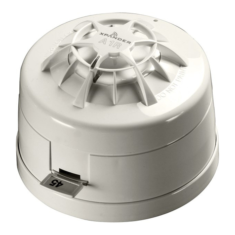
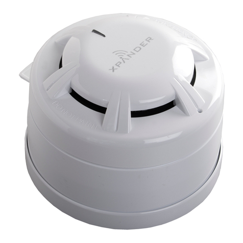
Apollo XPander User manual

Apollo

Apollo XPander User manual

Apollo Discovery ASD-1 User manual

Apollo

Apollo Discovery ASD-1 User manual

Apollo SA7100-100APO User manual

Apollo

Apollo SA7100-100APO User manual

Apollo REACH RW1000-460APO User manual

Apollo

Apollo REACH RW1000-460APO User manual

Apollo XPA-CB-11170-APO User manual

Apollo

Apollo XPA-CB-11170-APO User manual

Apollo 65 Series User manual

Apollo

Apollo 65 Series User manual

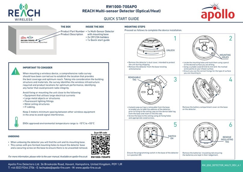
Apollo REACH WIRELESS RW1000-700APO User manual

Apollo

Apollo REACH WIRELESS RW1000-700APO User manual

Apollo 58000-300APO User manual

Apollo

Apollo 58000-300APO User manual

Apollo XP95A Series User manual

Apollo

Apollo XP95A Series User manual

Apollo XP95A Series User manual

Apollo

Apollo XP95A Series User manual

Apollo RoadRunner User manual

Apollo

Apollo RoadRunner User manual

Apollo Smoke Detector XP95 User manual

Apollo

Apollo Smoke Detector XP95 User manual

Apollo 55000-268 User manual

Apollo

Apollo 55000-268 User manual

Apollo ORB-OH-13001-APO User manual

Apollo

Apollo ORB-OH-13001-APO User manual

Apollo ORBIS ORB-OH-13003-APO User manual

Apollo

Apollo ORBIS ORB-OH-13003-APO User manual

Apollo Smoke Detector XP95 Operating and safety instructions

Apollo

Apollo Smoke Detector XP95 Operating and safety instructions

Apollo XP95 series User manual

Apollo

Apollo XP95 series User manual

Apollo XPander XPA-CB-12034-APO User manual

Apollo

Apollo XPander XPA-CB-12034-APO User manual

Apollo 55000-268 User manual

Apollo

Apollo 55000-268 User manual

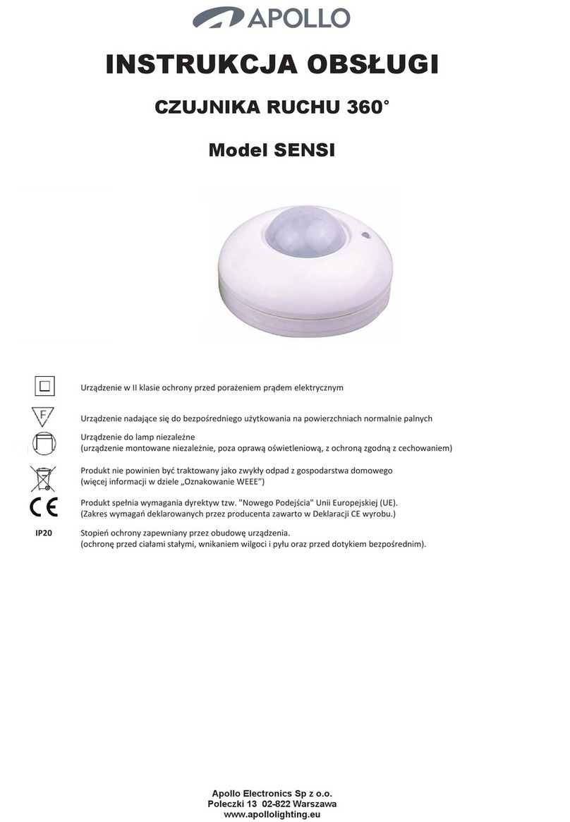
Apollo SENSI User manual

Apollo

Apollo SENSI User manual

Popular Security Sensor manuals by other brands

Optex OA-FUNXION quick start guide

Optex

Optex OA-FUNXION quick start guide

ZooZ ZSE42 800LR user manual

ZooZ

ZooZ ZSE42 800LR user manual

NuAire 230PIR installation guide

NuAire

NuAire 230PIR installation guide

iRay Technology Luna1012X user manual

iRay Technology

iRay Technology Luna1012X user manual

Vents CO2-1 user manual

Vents

Vents CO2-1 user manual

Bosch ISN-AP1-T installation guide

Bosch

Bosch ISN-AP1-T installation guide

Iget HOME XP4B installation manual

Iget

Iget HOME XP4B installation manual

Extech Instruments 401050 user guide

Extech Instruments

Extech Instruments 401050 user guide

Schabus SHT 5001 Operation manual

Schabus

Schabus SHT 5001 Operation manual

Bosch Truvo Original instructions

Bosch

Bosch Truvo Original instructions

BeNext MoLiTe quick start

BeNext

BeNext MoLiTe quick start

Ursalink EM300 Series user guide

Ursalink

Ursalink EM300 Series user guide

Baumer UNDK 20I6903/S35A manual

Baumer

Baumer UNDK 20I6903/S35A manual

olympia electronics BS-470 quick start guide

olympia electronics

olympia electronics BS-470 quick start guide

Interlogix ACL870SU-BSMF installation manual

Interlogix

Interlogix ACL870SU-BSMF installation manual

Johnson Controls PG9350SL user manual

Johnson Controls

Johnson Controls PG9350SL user manual

schmersal AZ 16-STS30-02 operating instructions

schmersal

schmersal AZ 16-STS30-02 operating instructions

Tyco SD-304C PG2 installation instructions

Tyco

Tyco SD-304C PG2 installation instructions

manuals.online logo
manuals.online logoBrands
  • About & Mission
  • Contact us
  • Privacy Policy
  • Terms and Conditions

Copyright 2025 Manuals.Online. All Rights Reserved.