APPLIED ACOUSTICS CSP-CSPD-8000/2 User manual

CAPACITOR CHARGING UNIT
CSP-CSPD-8000/2
MODELS COVERED IN THIS MANUAL:
CSP-D 2400
CSP-D 1200
CSP-D 700
ISSUE 2 JUNE 08

CSP-CSPD-8000/2- Section 1 Page 2 of 30

CSP-CSPD-8000/2- Section 1 Page 3 of 30
OPERATION MANUAL
Section 1

CSP-CSPD-8000/2- Section 1 Page 4 of 30
CONTENTS PAGE

CSP-CSPD-8000/2- Section 1 Page 5 of 30
1 Enviormental Considerations ............................ 9
2 Introduction ..................................................... 10
2 Installation ....................................................... 11
3 Operation ........................................................ 18
4 Operator Controls and Indicators .................... 23
5 Specifications ................................................... 28

CSP-CSPD-8000/2- Section 1 Page 6 of 30

CSP-CSPD-8000/2- Section 1 Page 7 of 30
WARNING
Information in this manual is copyright 1993 –2007, Applied Acoustic
Engineering Limited.
This manual is loaned without other consideration than the agreement and
condition that it is not to be reproduced, copied or otherwise disposed of
directly, and is not to be used in whole or in part to assist in or to furnish any
information for the making of drawings, prints, apparatus or parts thereof.
THIS EQUIPMENT CONTAINS LETHAL VOLTAGES,AND MUST
BE EARTHED AT ALL TIMES.
ENSURE ADEQUATE SAFETY PROCEDURES ARE EMPLOYED.

CSP-CSPD-8000/2- Section 1 Page 8 of 30

CSP-CSPD-8000/2- Section 1 Page 9 of 30
Seismic Sound Sources And Marine Life.
Although not proven, there is concern in some quarters that marine mammals may be
harmed or their behaviour changed by seismic activity. The sound pulses from sparkers
and boomers is much lower in amplitude and higher in frequency (so it will travel less far)
than air guns. However it makes sense that a precautionary approach to emitting sounds
in the whales and dolphins’ natural habitat should be observed.
The CSP energy sources described in this manual have the ability to “soft-start” and
increase the energy emitted in the water slowly over time and this technique will give any
marine mammals nearby the opportunity to escape before maximum signal amplitude is
reached. It will also give them a chance to get used to the noise if they choose to stay (!)
rather than being subjected to a sudden shock of a full power seismic signal.
The procedure is quite simple:-
By using a slow repetition rate –say at 1 pulse per 15 seconds and by using the “Auto”
charge rate, the energy will slowly increase over the course of several minutes. Once full
power has been achieved, the repetition rate can then be slowly increased until the rate
desired for the survey has been achieved.
Another factor to consider is to ensure that the start of any survey line is not in such a
location that any cetacian is trapped by the vessel and the noise, for example in a small
harbour. In such an instance, the survey should start in such a place that any cetacian in
the vicinity has a clear and rapid means of escape into open water and away from any
unnatural noise source. Further details and advice can be obtained from the following
web site:- http://www.jncc.gov.uk/pdf/Seismic_survey_guidelines_200404.pdf. This web
site refers to UK waters and relates to air guns as the sound source (in many ways
different to a sparker or boomer), but should serve as a useful guide nonetheless.

CSP-CSPD-8000/2- Section 1 Page 10 of 30
INTRODUCTION
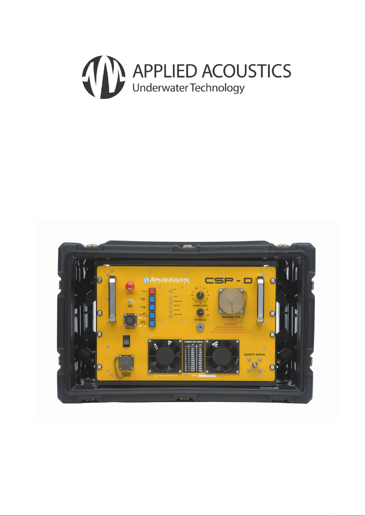
This manual covers the following CSP-D models available from AAE:
1) CSP-D 1200. Based on the highly proven CSP1500, the CSP-D 1200 has a high
voltage charger rated at 1500 joules per second, and can supply up to 1200 joules of
energy per shot into boomer and sparker loads. The CSP-D allows the user to select
HI and LO power levels this can effectively tune the source to a lower frequency
response. The CSP-D 1200 can be supplied with just 700J of energy storage
capacitors which allows for future upgrading.
2) CSP-D 2400. A higher capacity version of the CSP-D 1200, the CSP-D 2400 can
operate with low energies for boomer operations or large energies which are tailored
for use with the Squid 2000 sparker.
3) CSP-D 700. This is a lower capacity version of the above units and can be upgraded
to the full 1200 or 2400 joule specification at the factory.
The CSP-D’s incorporate many common parts and apart from the differing amounts of
energy storage, can be considered essentially as the same. All units feature a switchable
soft start ‘power save’ circuit; AVIP (Automatic Variable Input Power) which allows the
units to be operated from reduced generator sizes when operating at low output powers:-
Traditional high voltage power supplies (bang boxes) will charge the energy storage
capacitors at a fixed high rate for example at 1500J per second even when the average
energy drawn from the capacitors is less; a typical example may be 100 J at 3 pps
(300J). This results in a rapid capacitor charge rate for 67 mS followed by nothing, until
the next discharge / charge cycle. This charge / no charge operation can often result in
generator hunting as the load changes, and may mean that a larger generator is needed
than would be the case if the power requirement was averaged over time. By reducing
the peak charge rate, the generator hunting is all but eliminated, and a smaller capacity
generator is required. The AVIP circuitry will automatically adjust charge rate from 20%
to 100% of specification, thus lowering the peak charge rate to just 300 J / second
compared to bursts of 1500J/second. The circuitry also features a soft start function,
which may take around 20 seconds before the charge rate is ramped up to the correct
amount for the task in hand.
The CSP-D’s allow the user to effectively ‘tune’ the sound source to operate at a lower
frequency by lowering the operating voltage and increasing the capacitance to supply the
correct energy to the sound source. This maybe effective in certain instances where
more penetration is required.
The CSP-Ds monitor the output of the system for open circuit fault conditions and over
current fault conditions, limited to approx 5000A.

CSP-CSPD-8000/2- Section 1 Page 11 of 30
INSTALLATION
SITING THE CSP-D
The CSP-D units can deliver high energy, high voltage pulses, yet still emit minimal
electrical emissions, and so can carry the CE mark.
The CE marking ensure that the CSP-D’s can be sited next to sensitive electronic
equipment which carry their own CE marking (for susceptibility to emissions) and will be
unlikely to cause them interference. However it is often more convenient to locate the
CSP-D’s nearer to the back deck and the deployment area so that the high voltage
‘output’ cable run is minimised.
As high voltages are present, the CSP-D’s must be located away from water spray and
condensation, in an environment which is not allowed to become too hot. Care should be
taken to allow safe and easy access, and that high voltage cables are out of harms way.
It should also be possible to switch off the unit quickly without having to reach over it!
Ventilation should also be present. All units draw air in from the rear and exhaust air from
the front. For operation in high ambient temperatures, the rear cover of the transit case
should be removed to allow a good air flow.
If condensation is allowed to develop serious damage may occur. Good room ventilation
should be ensured, with no sudden change in temperature (ie bringing the unit into a
warm room from a cold area) and allow the fans to operate for 10 - 15 minutes before
switching on the high voltage.

CSP-CSPD-8000/2- Section 1 Page 12 of 30
EARTHING
All CSP-D’s MUST be earthed. The M8 earth bolt on the front panel should be connected
to the vessel earth by a heavy gauge wire or cable. On larger ships, earth is usually a
steel bulkhead, but for smaller fibre glass / wooden vessels a sea earth is necessary. A
sea earth can be constructed from a 25 mm2 or larger copper cable with 1 –2 metres of
insulation stripped off with all the exposed copper conductor in the water. A weight will be
required to ensure that the sea earth cable is in the water at all time during towing activity
even during heavy roll.
It is recommended that earthing arrangements are checked regularly as corrosion or
abrasion (or metal cutting gear!) can cause damage which may result in the equipment
becoming unsafe from having an ineffective earth.
The CSP-D range of Capacitor Discharge PSUs are compact and easy to operate.
However, the units still generate lethal voltages, and the operators should make
themselves aware of all necessary safety procedures. The equipment is designed so
that there is no need for the operator to go inside for anything, except major repairs. We
cannot be liable for any consequences should the units be opened. Health and Safety
guidelines and our own Safety Policy strongly suggest that factory training is received
before opening the top cover.
This manual is supplied in three parts:
Section 1
Basic operation information details.
Section 2
For manufacturer trained technicians
only and provides troubleshooting
advice, schematics and circuit
descriptions.
Section 3
Provides block and circuit diagrams.

CSP-CSPD-8000/2- Section 1 Page 13 of 30
OPERATION
INSTALLATION
The CSP-D Unit will normally be supplied from the factory in a ‘Hardigg’ transit case. As
is the case with all electronic equipment, care should be exercised in handling. For
maximum airflow in high ambient temperatures it is recommended that the anti-vibration
housing rear panel be removed. The CSP-D should be positioned on its base in a dry
ventilated area. Airflow for cooling is from back-to-front of the unit; there must be at least
50-60mm clear room from the rear panel to any obstruction. If the unit is to be operated
in very warm ambient temperature (25°C or above), for optimum performance an air
conditioned environment is strongly advised. If the unit overheats, it will switch OFF for a
few minutes until it is cool.
Although the unit produces minimal interference, and carries a CE mark, it is often good
practice to put the CSP-D away from the navigation and survey equipment and
somewhere where cabling to the sound source can be run conveniently and safely. It is
this cabling which is the most common source of electrical interference.
EARTHING - FURTHER REMINDER
THIS UNIT MUST BE EARTHED / GROUNDED BEFORE ANY POWER IS APPLIED.
FAILURE TO DO SO MAY REPRESENT A SEVERE HAZARD TO BOTH EQUIPMENT
AND PERSONNEL. The front of the CSP-D must be grounded to the ship’s ground
system. This is achieved by attaching a short length of thick wire or earth braid from the
CSP-D front panel earth stud, to an appropriate earthing point on the vessel. If a
suitable earth cannot be found, the CSP-D earth stud should be connected directly to the
water using an adequate length of heavy wire, with the insulation removed from the
submerged end in the water. A weight will also be necessary to keep the wire
submerged when the vessel is underway.

CSP-CSPD-8000/2- Section 1 Page 14 of 30
OUTPUT CABLE CONNECTION
ENSURE POWER TO UNIT IS TURNED OFF BEFORE ANY CONNECTIONS ARE
MADE. Connect the high voltage cable to the CSP-D front panel using the high voltage
connector. The HV connector has 2 small sensing pins which will deactivate the high
voltage if mains power is applied without the connector in place. Ensure the HV
connector is fully mated to the unit. The two larger sockets should never be at a high
potential but it makes sense never to attempt to touch these.
If you have our HV junction box, the two conductors of the acoustic source - boomer
plate or sparker should be connected to this before connecting to the CSP-D. The
terminal wing nuts should be tightened onto clean copper or tinned copper terminals. A
good connection is necessary as high currents pass through these terminals. Ensure that
the +ve or red terminal is connected to the + mark inside the HV Junction box. The black
or –ve terminal should be connected to the –mark inside the HV junction Box. Ensure
that the microswitch ‘clicks’ when the top cover is secured. The HV Junction Box can be
bulkhead mounted before the cover is secured. In the situation of the power cable /
sound source being caught on an object, the HV cable is pulled from the HV Junction
Box, rather than the CSP-D unit being pulled onto the floor.
The junction box is usually supplied with a 1.5 metre lead, terminated in our HV
connector. FOR OPTIMUM SAFETY THE JUNCTION BOX MUST BE GROUNDED TO
THE CSP-D FRONT PANEL. The junction box is fitted with a microswitch which is
connected to sense pins in the HV plug, ie deactivating the high voltage charger if the lid
is removed and the ‘INTERLOCK’ light will illuminate.

CSP-CSPD-8000/2- Section 1 Page 15 of 30
LINE VOLTAGE CONNECTION
Mains input is connected by the 3-Pin amphenol on the left of the front panel. Nominal
input voltage is 230VAC 45-65 Hz. The wiring to this connector is as follows:-
A : Ground / Earth
B : Neutral
C : Live
If a ready-wired plug is supplied, it will be supplied from the factory with the following
colour coding:-
Green/yellow : Earth
Blue : Neutral
Brown : Live
The operator must ensure that the ac supply is capable of supplying sufficient energy to
power the CSP-D unit. Although the unit will operate from most generators of 3 kVA, the
quality and regulation vary considerably from make to make and how well they have
been maintained. We have used 3.5 kVA generators without problems. A voltage
stabiliser is not necessary as any reasonable variation of the AC supply will not affect the
output voltage (hence power) unlike older designs.
NB Some ‘inverter’ type generators do not work well with CSP-D units.
The AVIP technology inside the unit can be utilised to reduce the generator
requirements. The CHARGE RATE switch has two positions (Located on rear panel)
IN : High Charge rate.
The charger delivers the full charge rate (1650 J/sec peak) on demand to
charge the storage capacitors.
OUT : Auto Charge rate.
The AVIP (Automatic Variable Input Power) circuitry is operational. This
adjusts the charge rate automatically to suit the capacitor selection and the
repetition rate used, and ensures that a constant current is drawn from the
AC mains supply. It is a soft start circuit and adjusts the charge rate by 5%
per sample; a sample occurs each trigger pulse. AVIP will adjust the charge
rate from 20% to 98%, thus allowing 100J 3pps operation from a 500 VA
generator. Note that it can take up to 16 samples for the charge rate to be
set to the correct amount.
AC POWER REQUIREMENTS

CSP-CSPD-8000/2- Section 1 Page 16 of 30
Voltage ratings are quoted elsewhere in this manual.
TYPICAL CURRENTS
At 1500J at 1 pps (AVIP out of circuit); Non PFC charger, the following currents apply:-
Voltage
Peak Current
Average Current
110 VAC 50 Hz
28A
19.7A
240 VAC 50 Hz
19.5A
7.9A
(At 60 Hz, the peak currents are slightly smaller)
To see clearly the effect of the AVIP board the following measurements are typical:-
240 VAC at 50 Hz supply. 100J at 1 pps output power
Peak Current
Average Current
AVIP IN
2.58A
1.06A
AVIP OUT
9.51A
1.11A
LINE VOLTAGE DERATING
The capability of the HV charger to deliver energy to the load (storage capacitors)
reduces with reduced line voltage as the following tables apply.
240 V Models.
Line Voltage
Charge Rate
180 VAC
1250 J/second
200 VAC
1400 J/second
210 VAC
>1500 J/second
115 V models
Line Voltage
Charge Rate
100 - 115 VAC
1300 J/second
116 –130 VAC
>1500 J/second
You may notice that the low line voltages above are below those specified in the rear of
this manual under ‘specifications’ The above tables denote the ability of the charger to
perform under certain line voltage conditions, and not the complete system. We do not
recommend operating the CSP-D units below the minimum voltages listed in the
specification section of this manual.

CSP-CSPD-8000/2- Section 1 Page 17 of 30
FURTHER REMINDER
If the unit has recently been moved from a cold environment to a warm one,
condensation may have developed, which may cause arcing in high voltage equipment.
The operator is advised to switch the unit on and run the fans for 10-15 minutes before
allowing the high voltage to be switched on. This will allow the unit to warm up to the
room temperature, and any condensation will disperse.
Power Up
When suitably connected to ground, the transducer and AC mains, and the transducer is
in the water, the power can be applied using the ON / OFF switch and circuit breaker.
The fans will run, and the HV OFF / RESET button will illuminate. Select the appropriate
power output required and press the RESET button to reset the internal circuitry. Turn
and hold the HV ENABLE KEY & simultaneously press the HV ON button: there will be a
small delay before the HV relays engage, and then the high voltage will come on as
indicated by the illuminated HV ON switch. Any changes in system parameters (such as
power change) will cause the HV to switch OFF, and the unit will need to be RESET
before the HV can be switched on again. If the INTERLOCK indicator illuminates, check
the HV plug / HV junction box.
Trigger Input
Trigger input is by BNC connector. The unit accepts +ve trigger (triggers on rising edge)
5 - 20 volts. opto-isolated, or by contact closure, as controlled by the KEY switch. (OUT
for +ve key, IN for contact closure.) The manual key button can be used too and this
also shows, by illumination, when a key pulse has been accepted. (A lockout circuit
limits the unit to around 6PPS maximum.)
Local / Remote
The LOCAL / REMOTE switch allows connection of remote box for operation from the
laboratory or instrument room. Using the remote box is achieved by turning the LOCAL /
REMOTE switch to remote. The high voltage can only be turned on from the instrument
room and not from the CSP-D Unit. The high voltage OFF button is operational from the
CSP-D Unit and remote box. The CSP Unit can also be keyed from the remote box via a
BNC socket. The remote also monitors the status of the key detect circuitry, and the key
LED will only illuminate on reception of a valid key pulse within the CSP-D itself, thus the
operator can also see if the interconnection cable is OK. The remote also has a FAULT
LED, as well as high voltage ON and high voltage OFF indicators.
LOCAL Operation indicated by LED on –Switch OUT.
REMOTE Opersation indicated by LED out –switch IN

CSP-CSPD-8000/2- Section 1 Page 18 of 30
OPERATION
Operation of the CSP-D is similar to previous versions of the CSP.
Installation check-list:-
a) The sound source (boomer plate or sparker) has been connected and that it is in
the water.
b) A key pulse is connected –either through the front panel BNC connector or
through the remote input.
c) A good earth has been connected from the ‘Safety Earth’ bolt on the front panel
preferably to both the ship and a sea earth.
d) AC mains is connected to the ‘Mains Input’ connector.
e) A safety check has been carried out to ensure that there is no-one in the water
and that crew members know that the unit is about to be operated.
Once switched on, the ‘HV OFF / RESET’ button must be pressed to reset any fault
latches and the light behind the ‘Manual Key’ button is flashing in sequence with the key
input signal. The output power can now be selected by using
the two rotary switches as shown in the accompanying
photographs. The two switches select a combination of
capacitor settings (labelled 1 –12) and voltage settings
(labelled LO and HI) so the operator can choose the power
setting required for the job in hand. Please see next section.
Once the appropriate setting has been made, the ‘HV ON’
button can be pressed whilst simultaneously turning the ‘HV
Enable’ keyswitch clockwise.
A series of up to 5 clicks will be heard depending on the
energy selected as the relays switch in circuit. Once these
relays have engaged, the high voltage is enabled.
If either of the power level switches is moved or if the HV
off/reset button is pressed, the unit will shut down safely. In
an emergency, the red ‘STOP’ button can be pressed.
The maximum repetition rate is governed by the charge rate (1500 Joules per second)
and the amount of capacitance selected. For example, at 300J / shot the CSP-D models
will run at 5 PPS. At 1200J (or 1250J), the CSP-D 1200 and 2400 will operate at 1 pulse
per second, with a little in reserve.

CSP-CSPD-8000/2- Section 1 Page 19 of 30
Energy Settings.
CSP-D 700
OUTPUT POWER
SWITCH POSITION
HI
LO
1
100
50
2
200
100
3
300
150
4
400
200
5
500
250
6
600
300
7
700
350
CSP-D 1200
OUTPUT POWER
SWITCH POSITION
HI
LO
1
100
50
2
200
100
3
300
150
4
400
200
5
500
250
6
600
300
7
700
350
8
800
400
9
900
450
10
1000
500
11
1100
550
12
1200
600
CSP-D 2400
OUTPUT POWER
SWITCH POSITION
HI
LO
1
100
50
2
200
100
3
300
150
4
500
200
5
750
300
6
1000
400
7
1250
500
8
1500
600
9
1750
700
10
2000
800
11
2250
900
12
2400
1000
Items marked in red are not suitable for a single boomer.
The blue column is unlikely to be suitable for sparker applications.
Operation of the CSP-D with a boomer sound source.

CSP-CSPD-8000/2- Section 1 Page 20 of 30
A boomer plate as a sound source produces a single pulse and the amplitude and
duration of this pulse is controlled by the energy going into it. The energy is derived from
the voltage and the quantity of energy stored in the CSP unit. Traditionally, boomers
have operated from around 3500 to 3800 volts. However a feature of the AA200 and
AA300 boomer plates is that they will produce a longer pulse (and hence more
penetration) with a lower voltage and higher capacitance from the energy source (CSP-
D). The LO voltage setting achieves this so, for example, using an AA300 boomer plate
at 200J at 3 pulses per second may be a common way of using the transducer with the
traditional 3.5 kV supply voltage using switch positions 2 and HI. However if position 4-
LO is used, the same energy is being applied to the transdcuer although at a lower
voltage, so the pulse length is increased.
Load Specifications:
The CSP-D units are designed to deliver high currents into boomer or sparker type loads.
The loads are quite different in make-up.
Boomer Load
A boomer plate consists of a coil imbedded in an epoxy or plastic material and thus by its
nature is an inductive load. The inductive ‘kickback’ is controlled by circuitry inside the
CSP. Typical currents into a boomer plate are listed below:-
Energy (HI)
AA200 Plate
EG+G Uniboom
100J
800A
900A
200J
1050A
1200A
300J
1250A
1350A
The currents will vary according to the length and type of cable used between the load
and the energy source. Note that the CSP-D units are specified for AAE and EG+G
boomer plates and have not –to date- been tested with any other type.
Ensure that the energy and repetition rate do not over drive the sound source ! (boomer
plate - check the boomer plate manual).
This manual suits for next models
3
Table of contents
Other APPLIED ACOUSTICS Batteries Charger manuals