Aprilaire 65 User manual

The Model 65 humidifier control is for use with any humidifier
requiring an ON/OFF signal for a 24 volt circuit.
SAFETY INSTRUCTIONS
WARNING
1. Improper installation may cause property damage or injury. Installation, service, and
maintenance must be performed by a qualified service technician.
2. 120 Volts may cause serious injury from electric shock. Disconnect electrical power before
starting installation or servicing. Leave power disconnected until installation/service is
completed. This control is not a 120 Volt (line voltage) device.
CAUTION
1. Read all instructions before beginning installation.
2. Do not adjust humidity set-point above recommended level or to recommended level
if condensation occurs on inside surface of windows or on other surfaces. Excess
condensation can cause damage to structure or furnishings. Excess moisture can also
allow the possibility for mold growth to occur.
3. Do not use solvents or cleaners on or near the display and circuit board. Chemicals can
damage components.
Model 65
Humidifier Control
Installation Instructions
READ AND SAVE THESE INSTRUCTIONS
1

TABLE OF CONTENTS
SAFETY INSTRUCTIONS � � � � � � � � � � � � � � � � � � �1
OVERVIEW � � � � � � � � � � � � � � � � � � � � � � � � � � � � � � 2
SPECIFICATIONS � � � � � � � � � � � � � � � � � � � � � � � � � 2
MATERIALS PROVIDED � � � � � � � � � � � � � � � � � � � 3
LOCATION RECOMMENDATIONS � � � � � � � � � � 3
INSTALLATION
Mount Control� � � � � � � � � � � � � � � � � � � � � � � � � � 4
Wiring� � � � � � � � � � � � � � � � � � � � � � � � � � � � � � � � � 5
MATERIALS PROVIDED
• Wall-Mount Control
• Mounting Screws
• Drywall Anchors
• RH Setting Label
MOUNT CONTROL
• In an area the homeowner wants to
monitor and control moisture levels�
• On an interior wall�
• Approximately 5 feet off the floor�
• At least 18" from an outside wall�
MATERIALS NOT PROVIDED
• Wires
• Wire Nuts
DO NOT MOUNT CONTROL
• In the flow of a supply register.
• Behind doors, in corners or other dead air spaces�
• In direct sunlight, near lighting fixtures, or other
appliances that give off heat�
• On an outside or unconditioned area wall�
• In stairwells or near outside doors�
• On a wall with concealed pipes or ductwork�
SYSTEM CHECKOUT
Power Up� � � � � � � � � � � � � � � � � � � � � � � � � � � � � � 9
Test Mode � � � � � � � � � � � � � � � � � � � � � � � � � � � � 10
Humidity Setting � � � � � � � � � � � � � � � � � � � � � � 10
Offset � � � � � � � � � � � � � � � � � � � � � � � � � � � � � � � � 10
Turning On and Setting the Control� � � � � � � 11
Sequence of Operation� � � � � � � � � � � � � � � � � � 11
TROUBLESHOOTING
Error Codes � � � � � � � � � � � � � � � � � � � � � � � � � � � � 11
Troubleshooting Guide � � � � � � � � � � � � � � � � � �12
MATERIALS PROVIDED
A self-adhesive label (RH Setting Label) showing recommended RH settings based on outdoor
temperature is provided� The label can be attached to the front of the control to serve as a guideline
and a reminder for the homeowner to adjust the RH setting as outdoor temperature changes�
LOCATION RECOMMENDATIONS
OVERVIEW
The Aprilaire® Model 65 Humidifier Control provides control of the humidifier from the living
space� The control allows the homeowner to set and adjust the humidity setting and turn the
humidifier on or off from a convenient location� The Model 65 uses an onboard sensor to monitor
the relative humidity in the space in which it is located and displays the measured relative
humidity on the digital display�
SPECIFICATIONS
ELECTRICAL
Input Voltage and Current Voltage: 24V AC +/-20%
Current: 25mA (nominal), 50mA (max�) at 24V AC
Output Dry Contact, Normally Open – H Terminals
CONTROL
Humidity Setting Range 10% – 50% RH
Accuracy +/-5% RH
Differential 3%
Low Temp 40°F
High Temp 99°F
5
FEET
NONO
18"
MINIMUM
NO
90-1640
FIGURE 1 – MOUNTING LOCATION
32

INSTALLATION
MOUNT CONTROL
See FIGURES 2 & 3�
1. Remove front cover by pulling straight out�
2. Position the back plate on the wall and mark the locations for the wire access hole and the
mounting screws� Note: The mounting holes can also be used to secure the back plate to a
standard horizontally mounted junction box�
3. For mounting on drywall, drill two 3/16" dia� mounting holes and a 3/4" opening for the wires�
4. Insert the drywall anchors provided into the mounting holes flush with the wall surface�
5. Run 4-wire cable from the humidifier to the control location�
6. Secure back plate using the two #8 x 1-1/2" screws provided�
7. After connecting the wires, tuck excess wire into the wall and fill the opening with insulating
material� Failure to seal the opening may result in inaccurate operation due to drafts�
PULL APART
BACK PLATE
RH SETTING LABEL
FRONT COVER
90-2497
FIGURE 2 – DISASSEMBLE CONTROL
ANCHOR
BACK PLATE
SCREW
4-CONDUCTOR WIRE
WIRE ACCESS
OPENING
MOUNTING HOLES
90-2498
FIGURE 3 – MOUNT BACK PLATE
WIRING
WIRING MODEL 65 WITH APRILAIRE MODEL 400, 500, 600, AND 700 SERIES EVAPORATIVE
HUMIDIFIERS
The Model 65 control requires 24VAC� Drawing power from the HVAC system is the recommended
method for this installation� See FIGURES 4 & 5�
1. Disconnect power to the humidifier and HVAC system�
2. Connect the C and R terminals on the Model 65 to the HVAC or thermostat C and R terminals�
3. Connect Model 65 H terminals to the humidifier solenoid valve control circuit as shown�
4. Snap the front cover onto the back plate� The 4-pin terminal aligns with the terminal block
receptacle on the back plate�
5. Proceed to SYSTEM CHECKOUT on page 9�
54

C
R
G
W
Y
24V
ACCESSORY
TERMINALS
H
H
R
C
APRILAIRE
EVAPORATIVE
HUMIDIFIER
SOLENOID VALVE
CIRCUIT WIRES
MODEL 65 CONTROL
HVAC EQUIPMENT
H
H
R
C
C
R
APRILAIRE
EVAPORATIVE
HUMIDIFIER
SOLENOID VALVE
CIRCUIT WIRES
MODEL 65 CONTROL
HVAC EQUIPMENT
24VAC
CONTINUOUSLY POWERED
TRANSFORMER
COMMON
MOTOR LEAD
HVAC BLOWER
MODEL 50
RELAY
90-2499
90-2500
FIGURE 4 – RECOMMENDED WIRING FOR MODEL 65 CONTROL AND EVAPORATIVE HUMIDIFIER
FIGURE 5 – ALTERNATE WIRING FOR MODEL 65 CONTROL AND EVAPORATIVE HUMIDIFIER
WIRING MODEL 65 WITH MODEL 800 STEAM HUMIDIFIER
The Model 65 control requires 24VAC� See FIGURE 6�
1. Disconnect power from the Model 800 and HVAC system�
2. Connect 24VAC to the C and R terminals on the Model 65�
3. Connect the H terminals on the Model 800 to the H terminals on the Model 65�
4. Snap the Model 65 front cover on the back plate� The 4-pin terminal aligns with the terminal
block receptacle on the back plate�
5. Proceed to SYSTEM CHECKOUT on page 9�
Note: If the Model 800 Steam Humidifier is installed with a Model 850 Fan Pack, the Model 65
Control can be powered from the 24VAC secondary wires on the Model 800 transformer, by
splicing into the wires using tap connectors� See FIGURE 7�
Y
G
W
R
C
Y
G
W
R
C
BLUE (NC)
ORANGE (NO)
YELLOW (C)
WHITE/YELLOW
WHITE/BLUE
FAN PACK HUMIDISTAT
H
H
R
C24VAC
REMOVE WIRE
"G" TO "G"
APRILAIRE MODEL 800
STEAM HUMIDIFIER
MODEL 65 CONTROL
TYPICAL 24 VAC
TERMINAL STRIP
IN FURNACETHERMOSTAT
APRILAIRE
4851 RELAY
CONSTANT 24 VAC
POWER SOURCE
NOTE: 18 AWG WIRE
IS ACCEPTABLE FOR
24V INSTALLATIONS.
APRILAIRE MODEL 800 STEAM HUMIDIFIER WITH MODEL 65 DIGITAL
MANUAL CONTROL AND #4851 BLOWER ACTIVATION RELAY
90-2503
FIGURE 6 – RECOMMENDED WIRING FOR MODEL 65 CONTROL AND MODEL 800 STEAM HUMIDIFIER
76

FAN PACK HUMIDISTAT
H
H
R
C
TAP CONNECTORS
CIRCUIT BOARD
TRANSFORMER
MODEL 850 STEAM HUMIDIFIER FAN PACK
APRILAIRE MODEL 800
STEAM HUMIDIFIER
24VAC
24VAC
P4
MODEL 65 CONTROL
NOTE: 18 AWG WIRE IS ACCEPTABLE
FOR 24V INSTALLATIONS.
90-2502
FIGURE 7 – RECOMMENDED WIRING FOR MODEL 65 CONTROL AND
MODEL 800 STEAM HUMIDIFIER WITH MODEL 850 FAN PACK
SYSTEM CHECKOUT
POWER UP
1. Check all wiring�
2. Restore power to the HVAC system and humidifier�
3. After a 4 second start up sequence all buttons on the Model 65 will be functional�
• The control will be OFF�
• The humidity setting will be 30%�
• The control will display the measured humidity�
90-2495
90-1670
FIGURE 8 MODEL 65 CONTROL
MODEL 65 LCD DISPLAY
Blinking ON + *:Temp Limits Exceeded�
See Operating Limits, page 11�
Solid ON:
Control On
Blinking ON:
Humidifying
Measured
Humidity or
Setting Control On/Off
Humidity Setting
and Offset
Adjustment
Control must be
ON to adjust offset
and setting.
SET: Shows when
humidity setting
displayed or being
changed�
OFF: Control Off
98

TEST MODE
1. Press and hold the ON button for 5 seconds to enter Test Mode�
a. Verify all LCD segments blink every second�
b. Verify humidifier turns on�
2. After 5 minutes or after pressing the OFF button, the control will enter Off mode�
a. Verify the humidifier turns off�
HUMIDITY SETTING
• The control must be ON to adjust the humidity setting�
• The (up) and (down) buttons are used to increase or decrease the humidity setting�
• The first press of either button will display the current setting on the LCD display and SET will
be displayed below the %sign�
• Each subsequent push of the or buttons will change the setting by 1%�
• If a button is held down, the setting will continually change by 1% every 1/2 second for as long
as the button is pressed�
• The control will return to Normal Mode, displaying the measured humidity, 5 seconds after the
last button press/release�
OFFSET
An offset can be applied to the humidity reading to avoid discrepancies with other humidity
measuring devices in the home� Allow 48 hours for the control to acclimate before applying an
offset� The control must be ON to enter the Offset screen�
• Press and hold the OFF button for 5 seconds
to enter the Offset screen� See FIGURE 9�
• The buttons can be used to set an
offset value between -5% RH and +5% RH�
• The control will return to Normal Mode,
displaying the measured humidity, 5
seconds after the last button press/release�
FIGURE 9 – OFFSET SCREEN
90-1638
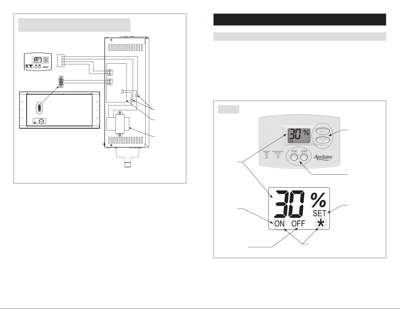
TURNING ON AND SETTING THE CONTROL
1. Press the ON button�
2. Use the buttons to set the control at 30%�
Increasing the humidity setting will increase humidifier run time, resulting in higher
humidity levels�
Decreasing the humidity setting will decrease humidifier run time, resulting in lower
humidity levels�
SEQUENCE OF OPERATION
Normal Mode
• When the measured humidity is lower than the setting, the control will activate the humidifier,
and ON will blink on the LCD display�
• When the measured humidity increases to 3% RH above the setting, the control will deactivate
the humidifier, and the LCD will display a solid ON�
Operating Limits
• If the control senses temperature below 40°F or above 99°F, the control will not allow the
humidifier to operate, and ON and *will blink on the display�
• The control will resume normal operation once the temperature is within the specified limits�
TROUBLESHOOTING
Technical Support is available Monday through Friday, 7:00 a�m� to 5:00 p�m� CST, at
(800)334-6011� Use the guide on the following page to help find and correct system faults�
Contact Technical Support before replacing the control or for additional troubleshooting�
ERROR CODES
When the control detects an internal error, it
will stop controlling, deactivate the humidifier,
and the LCD will display the Error Code� See
FIGURE 10� The control will attempt to recover
from the error every 10 minutes� The Error
Code will continue to be displayed as long as
the error condition exists� Button presses are
not registered when in Error Mode� Cycling
power to the control will not clear the code
and the control will need to be replaced�
FIGURE 10 – ERROR CODE SCREEN
90-1645
1110

TABLE 1 – TROUBLESHOOTING GUIDE
Symptom Possible Reason Troubleshooting Procedure
No power to the
control�
Incorrect wiring� Verify wiring connections between control,
humidifier and HVAC system (where applicable)�
No power to humidifier� • Verify that the humidifier is wired correctly�
• Verify the circuit breaker has not tripped�
No power to HVAC
equipment�
• Verify HVAC system switch is on�
• Verify the circuit breaker has not tripped�
Control does
not turn on
humidifier�
Incorrect wiring� Verify wiring connections between control and
humidifier�
Display does
not blink all LCD
segments during
Test Mode�
LCD error� Replace control�
Display shows EE�Control detected an internal
error� Replace control�
Inaccurate
humidity reading�
Control recently installed
after being stored in an
uncontrolled temperature
and humidity environment�
Allow 48 hours for control to acclimate�
Offset has been applied to
the humidity reading� Change the offset�
Control is mounted in direct
sunlight, above a heat or
humidity source, or in the
path of a supply register�
Relocate the control�
AprilairePartners.com
P.O. Box 1467
Madison, WI 53701-1467
800.334.6011 F: 608.257.4357
Printed in USA
©2019 Aprilaire – Division of Research Products Corporation
61001733 B2208472A 7.19
12
Other manuals for 65
2
Table of contents
Other Aprilaire Control Unit manuals