Aprilaire 8120 Setup guide
Other Aprilaire Controllers manuals
Aprilaire
Aprilaire 70 User manual

Aprilaire
Aprilaire 76 User manual
Aprilaire
Aprilaire IN72 User manual

Aprilaire
Aprilaire Zoned Comfort User manual
Aprilaire
Aprilaire 8120 User manual

Aprilaire
Aprilaire 1150 Setup guide
Aprilaire
Aprilaire 4838 User manual

Aprilaire
Aprilaire 8120 Setup guide
Aprilaire
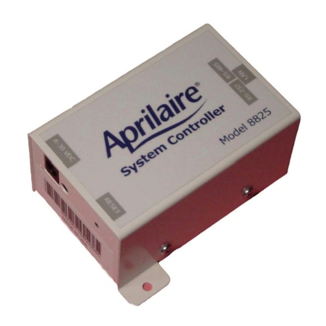
Aprilaire 8825 Quick guide
Aprilaire
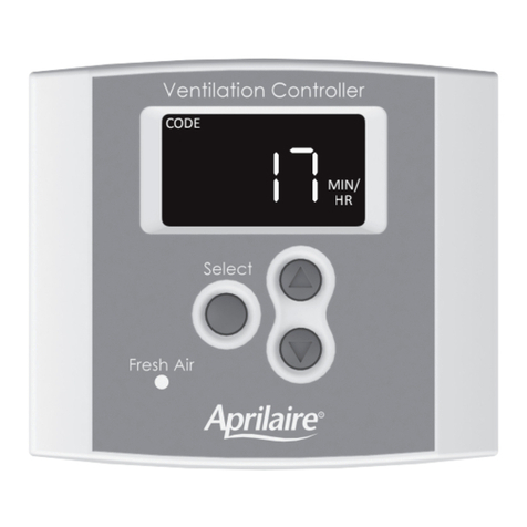
Aprilaire 8120X User manual

Aprilaire
Aprilaire 8120 User manual

Aprilaire
Aprilaire 8120 User manual
Aprilaire
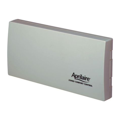
Aprilaire Zoned Comfort Control 6202 User manual
Aprilaire
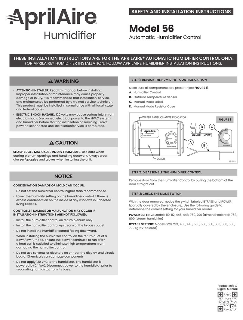
Aprilaire 56 Setup guide

Aprilaire
Aprilaire 75 User manual
Aprilaire
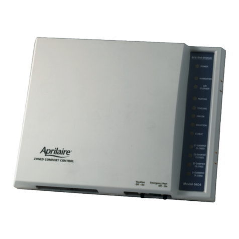
Aprilaire 6404 Setup guide
Aprilaire
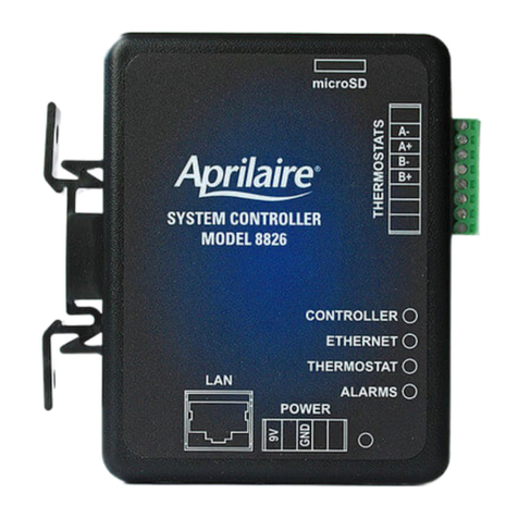
Aprilaire 8826 Quick guide
Aprilaire
Aprilaire 8126 User manual

Aprilaire
Aprilaire Zoned Comfort Control 6202 User manual

Aprilaire
Aprilaire Zoned Comfort User manual
Popular Controllers manuals by other brands

Digiplex
Digiplex DGP-848 Programming guide

YASKAWA
YASKAWA SGM series user manual

Sinope
Sinope Calypso RM3500ZB installation guide

Isimet
Isimet DLA Series Style 2 Installation, Operations, Start-up and Maintenance Instructions

LSIS
LSIS sv-ip5a user manual

Airflow
Airflow Uno hab Installation and operating instructions
