manuals.online logo
Brands
  1. Home
  2. •
  3. Brands
  4. •
  5. Aprilaire
  6. •
  7. Controllers
  8. •
  9. Aprilaire 60 Setup guide

Aprilaire 60 Setup guide

Other manuals for 60

2

This manual suits for next models

1

Other Aprilaire Controllers manuals

Aprilaire 1150 Setup guide

Aprilaire

Aprilaire 1150 Setup guide

Aprilaire Zoned Comfort User manual

Aprilaire

Aprilaire Zoned Comfort User manual
Aprilaire 8120 User manual

Aprilaire

Aprilaire 8120 User manual

Aprilaire 8120 User manual

Aprilaire

Aprilaire 8120 User manual

Aprilaire Zoned Comfort Control 6202 User manual

Aprilaire

Aprilaire Zoned Comfort Control 6202 User manual

Aprilaire 8126A User manual

Aprilaire

Aprilaire 8126A User manual

Aprilaire 8126 User manual

Aprilaire

Aprilaire 8126 User manual

Aprilaire 70 User manual

Aprilaire

Aprilaire 70 User manual

Aprilaire 76 User manual

Aprilaire

Aprilaire 76 User manual

Aprilaire Zoned Comfort User manual

Aprilaire

Aprilaire Zoned Comfort User manual

Aprilaire 8120X User manual

Aprilaire

Aprilaire 8120X User manual

Aprilaire IN72 User manual

Aprilaire

Aprilaire IN72 User manual

Aprilaire 75 User manual

Aprilaire

Aprilaire 75 User manual

Aprilaire 8826 Quick guide

Aprilaire

Aprilaire 8826 Quick guide
Aprilaire 8120 User manual

Aprilaire

Aprilaire 8120 User manual

Aprilaire 8910 User manual

Aprilaire

Aprilaire 8910 User manual

Aprilaire 56 Setup guide

Aprilaire

Aprilaire 56 Setup guide

Aprilaire 60 Setup guide

Aprilaire

Aprilaire 60 Setup guide

Aprilaire 8825 Quick guide

Aprilaire

Aprilaire 8825 Quick guide

Aprilaire 76 User manual

Aprilaire

Aprilaire 76 User manual

Aprilaire 8120 User manual

Aprilaire

Aprilaire 8120 User manual

Aprilaire 65 User manual

Aprilaire

Aprilaire 65 User manual
Aprilaire 8120 Setup guide

Aprilaire

Aprilaire 8120 Setup guide

Aprilaire 6404 Setup guide

Aprilaire

Aprilaire 6404 Setup guide

Popular Controllers manuals by other brands

Sunricher SR-ZV9003T3-RGBW-US Installation

Sunricher

Sunricher SR-ZV9003T3-RGBW-US Installation

Ksenia intro Installation and configuration manual

Ksenia

Ksenia intro Installation and configuration manual

Inovance CAN200 Series manual

Inovance

Inovance CAN200 Series manual

Gauzy LC6 FLEX Controller Installation and operation guide

Gauzy

Gauzy LC6 FLEX Controller Installation and operation guide

Viking SLP-1 Technical practice

Viking

Viking SLP-1 Technical practice

CKD KBX-30E-U Series instruction manual

CKD

CKD KBX-30E-U Series instruction manual

Sharp Energy Sun Flux User manual & installation guide

Sharp Energy

Sharp Energy Sun Flux User manual & installation guide

Yamaha RCX40 user manual

Yamaha

Yamaha RCX40 user manual

AB Quality PowerFlex 400 Frames D-H Service bulletin

AB Quality

AB Quality PowerFlex 400 Frames D-H Service bulletin

Yamaha MJC8 owner's manual

Yamaha

Yamaha MJC8 owner's manual

AL-KO ATC operating instructions

AL-KO

AL-KO ATC operating instructions

Savant SmartControl 2 Deployment guide

Savant

Savant SmartControl 2 Deployment guide

GameSir T3S user manual

GameSir

GameSir T3S user manual

Kostal inveor operating manual

Kostal

Kostal inveor operating manual

Emerson Yarway 20-55 Operating and safety instructions

Emerson

Emerson Yarway 20-55 Operating and safety instructions

CoCo ACM-LV24 Quick installation guide

CoCo

CoCo ACM-LV24 Quick installation guide

Brooks SLA5810/20 Installation and operation manual

Brooks

Brooks SLA5810/20 Installation and operation manual

SIGMA TEK SR 011 Technical manual

SIGMA TEK

SIGMA TEK SR 011 Technical manual

manuals.online logo
manuals.online logoBrands
  • About & Mission
  • Contact us
  • Privacy Policy
  • Terms and Conditions

Copyright 2025 Manuals.Online. All Rights Reserved.

Automatic
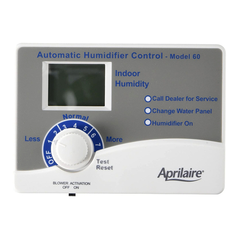
Digital Humidifier Control
Model 60 &62
Safety and Installation Instructions
WARNING
ATTENTION INSTALLER: T is product must be
installed by a qualified eating and air conditioning
contractor. Failure to do so could result in serious
injury from electrical s ock.
READ COMPLETE INSTALLATION INSTRUCTIONS
AND TEMPLATE BEFORE STARTING INSTALLATION.
Model 60 shown.
All manuals and user guides at all-guides.com
all-guides.com
32
G tting Start d . . . . . . . . . . . . . . . . . . . . . . . . . . . . . . . . . . .pag 3
Installation . . . . . . . . . . . . . . . . . . . . . . . . . . . . . . . . . . . . . . .pag 7
Syst m Ch ckout . . . . . . . . . . . . . . . . . . . . . . . . . . . . . . . . .pag 19
Troubl shooting Guid . . . . . . . . . . . . . . . . . . . . . . . . . . . .pag 21
TABLE OF CONTENTS
THESE INSTALLATION INSTRUCTIONS
ARE FOR THE APRILAIRE®AUTOMATIC DIGITAL
HUMIDIFIER CONTROL ONLY!
For Aprilaire®humidifier installation,
follow Aprilaire Humidifier Installation Instructions.
WARNING
Hazardous Voltage can cause serious injury
from electric s ock.
Disconnect electrical power to t e furnace and
umidifier before starting installation.
Sharp edges can cut.
Wear gloves and use care w en cutting plenum
openings and andling ductwork.
CAUTION
Condensation damage may occur.
Do not set umidifier control ig er t an
recommended.
Lower t e umidity setting if t ere is excess
condensation on t e inside of any windows in
un eated living spaces.
Install according to t e enclosed installation
instructions.
Controller damage or malfunction may occur
if installation instructions are not followed.
Install umidifier control on return plenum only.
Install umidifier control upstream of t e bypass
outlet or steam dispersion tube.
Do not install umidifier control facing downward.
GETTING STARTED
STEP 1: Unpack the Humidifier Control Carton
Mak sur all compon nts ar pr s nt (s Figure A):
A. Humidifi r Control
B. Outdoor T mp ratur S nsor
C. Manual Mod Lab l
B
AC
Figure A 90-1201B
All manuals and user guides at all-guides.com
54
STEP 2: Disassemble the Humidifier Control
R mov th knob. R mov th cov r by pulling at th bottom and
swinging it out and upward. S Figur Bto b com familiar
with th t rminal positions. Figur s Kand Lshow compl t
installation wiring diagrams for Aprilair Humidifi rs.
Figure B – Digital Humidifier Control 24V Terminals
90-1397B
HHGfW GODTBACR
OUTDOOR
TEMPERATURE
SENSOR
24 VAC FROM
HVAC EQUIPMENT
“R” AND “C”
COMMUNICATION
WITH APRILAIRE
8570 THERMOSTAT
HEAT SIGNAL
FROM HVAC
EQUIPMENT
FAN SIGNAL
FROM
THERMOSTAT
SOLENOID
CONTROL
OUTPUT
FAN SIGNAL
TO HVAC
EQUIPMENT
R v rsing th Rand Ct rminals on humidifi r control
will caus improp r op ration.
Water Panel
Indicator
Settings
STEP 3: Set the Change Water Panel Indicator
This s tting will control wh n th indicator light turns on,
r minding you to chang your wat r pan l. If your Control cam
with a humidifi r, th Control is pr -s t for th humidifi r. If th
installation sit has a 3-month or short r h ating s ason or v ry
hard wat r, you may want to adjust th s tting (s Figure C).
Set to “OFF” for Mod l
800 S ri s humidifi rs or
to turn th Humidifi r Pad
Chang indicator to off.
Set to “A” for Mod l
400 S ri s humidifi rs
in ar as with v ry hard
wat r. Th indicator
will light aft r 150
hours of op ration.
Set to “B” for Mod l 400
S ri s humidifi rs; and
Mod l 500 S ri s, 600
S ri s and 700 S ri s
humidifi rs in ar as with
v ry hard wat r. Th
indicator will light aft r
300 hours of op ration.
Set to “C” for Mod l 500 S ri s, 600 S ri s
and 700 S ri s humidifi rs. Th indicator will
light aft r 600 hours of op ration.
Figure C
90-1202B
All manuals and user guides at all-guides.com
76
STEP 4: Blower Activation Feature Explanation
S t th Blow r Activation switch to “ON”, s Figure J, to allow
th Humidifi r Control to activat th furnac fan for additional
humidification. This may b r quir d if th humidifi r is mount d
on a h at pump or a furnac with short run cycl s. Wh n using
th Blow r Activation f atur , Mod l 400, 500, 600 and 700
s ri s humidif rs must b plumb d to hot wat r for ff ctiv
op ration.
Wh n th Blow r Activation switch is “ON”, th Humidifi r
Control will turn on th HVAC blow r wh n humidity is r quir d.
In th “OFF” position, th humidifi r will only op rat if humidity
is r quir d and th HVAC syst m is op rating.
Wh n th Blow r Activation switch is “ON”, th Humidifi r
Control may xt nd th HVAC blow r aft r a h at call for up to
two hours. If th HVAC syst m has b n idl for on hour, th
control will turn th blow r on for thr minut s to sampl
hous hold air to d t rmin if humidity is n d d.
NOTE: If us d in conjunction with an Aprilair 8570
Communicating Th rmostat, and th blow r activation f atur is
d sir d, DO NOT wir th A B communication t rminals.
Th Mod l 62 shipp d with th Mod l 800 St am Humidifi r is
factory s t to “OFF”. Th Mod l 62 do s not hav th “Chang
Wat r Pan l” light on th Control. Th Canist r Chang indicator
for th Mod l 800 is on th humidifi r. STEP 1: Mount the Humidifier Control
Humidifi r Control must b mount d on th R turn Duct, at l ast
6 inch s upstr am of th following (s Figure D):
• Humidifi r
• Humidifi r Bypass Ductwork (if applicabl )
• Fr sh Air Intak Ductwork (if applicabl )
For accurat humidity control, mount th Humidifi r Control at
l ast 12 inch s upstr am of th St am Humidifi r disp rsion tub .
Ambi nt op rating t mp ratur of th Humidifi r Control is to b
from 20°F to 120°F to pr v nt damag to th control display.
90-1137
6" MIN.
RETURN
DUCT
HUMIDIFIER
CONTROL
FRESH AIR
INTAKE
COIL
HUMIDIFIER
BYPASS
CONNECTION
INSTALLATION
Figure D
All manuals and user guides at all-guides.com
98
DUCT (SHEET METAL) MOUNT:
Aft r location for Control is s l ct d, drill a 3/4 inch hol for th
RH s nsor (th RH s nsor xt nds from th back of th
Humidifi r Control).
Us 2 sh t m tal scr ws, 3/4 inch long (not provid d), to mount
th Humidifi r Control. Us th mounting slot to l v l th Control,
th n s cur th Control with th s cond sh t m tal scr w.
Mak sur th Humidifi r Control s nsor gask t is s at d tightly
around th drill d hol . Do not install Control without gask t.
CAUTION
Controller damage or malfunction may occur if
installation instructions are not followed.
Install umidifier control on return plenum only.
Install umidifier control upstream of t e bypass
outlet or steam dispersion tube.
Do not install umidifier control facing downward.
DUCT (FIBER BOARD) MOUNT:
Aft r location for Control is s l ct d, cut a r ctangular hol in
th duct board, no small r than 6-9/16 inch s long by 4-3/8
inch s wid .
Cut a r ctangular pi c of sh t m tal to fit b hind th hol in
duct board for mounting th Humidifi r Control.
Drill a 3/4 inch hol for th RH s nsor (th RH s nsor xt nds from
th back of th Humidifi r Control) into th sh t m tal plat .
Us 2 sh t m tal scr ws, 3/4 inch long (not provid d), to mount
th Humidifi r Control.
Mak sur th Humidifi r Control s nsor gask t is s at d tightly
around th drill d hol . Do Not Install Control Without Gask t.
S cur th sh t m tal plat , with th Humidifi r Control
mount d, insid th duct (s Figure E).
CONTROL REPLACEMENT:
Wh n r placing an xisting control, th duct op ning l ft by th
r mov d control must b cov r d compl t ly. Locat and install
th n w control as instruct d pr viously in this st p.
All manuals and user guides at all-guides.com
1110
90-1203B
CONTROL BOARD
COVER
KNOB
BASE PLATE
RETURN DUCT
RETURN
DUCT
SHEET METAL
PLATE
CUT OPENING IN
RETURN DUCT
SHEET METAL PLATE
GASKET
SCREW (x2)
INSIDE OF
RETURN
DUCT
STEP 2: Determine Location for and Mount Outdoor
Temperature Sensor
Th location of th Outdoor T mp ratur S nsor must m t
th s thr r quir m nts:
1. Must b mount d on North, East or W st sid of hous out of
dir ct sunlight.
2. Must b at l ast 3 f t from all xhaust v nts.
3. Must b abov xp ct d snow lin (s Figure F).
Incorr ct humidity l v ls will r sult if th s r quir m nts ar not
m t.
S cur s nsor brack t with a #8 galvaniz d scr w.
Figure F NORTH, EAST
OR WEST SIDE
OF HOME
OUTDOOR
TEMPERATURE
SENSOR
SENSOR
BRACKET
SENSOR
ABOVE EXPECTED
SNOW LINE
OUTDOOR
TEMPERATURE SENSOR
LEADS
90-998
NOTE: A conv ni nt way to g t th S nsor wir outsid is to
mak us of unus d wir s running to th A/C cond nsing unit
(if applicabl ). Oth r ways ar to us xisting hol s for Cabl TV
lin s, t l phon lin s, A/C lin s, tc. R ad all quipm nt
instructions b for hand for possibl conflicts and warnings.
Figure E – Fiber Board Duct Mount
All manuals and user guides at all-guides.com
all-guides.com
1312
STEP 3: Alternate Location for Outdoor
Temperature Sensor
Wh n mounting th Outdoor T mp ratur S nsor in an intak air
duct th turn th Blow r Activation switch (s Figure J) to
“OFF”. If l ft in th “ON” position, ov r humidification and
cond nsation damag could occur.
Th S nsor can b mount d with a #8 galvaniz d scr w in th
c nt r of ith r:
• PVC fr sh air intak pip for th HVAC syst m.
OR
• A fr sh air intak duct.
In both cases, the Sensor must be no more than 3 feet
from the outside wall. See Figure G.
If it is not f asibl to us th Outdoor T mp ratur S nsor in any
of th ways d scrib d, th Humidifi r Control can b install d for
Manual Op ration. S “Installing th Humidifi r Control for
Manual Op ration” and Figure J for d tails.
Figure G
3 FEET MAX.
CENTER LINE
OUTSIDE WALL
90-999
STEP 4: Route the Wire from Control to Sensor
Run wir to th outdoor t mp ratur s nsor. S nsor is accurat
with l ad l ngths up to 300 ft.
STEP 5: Attach Sensor Wire to Humidifier Control
Strip wir 1/4 inch, and ins rt th wir s from th S nsor into th
t rminals lab l d “ODT” on th Humidifi r Control. S Figure H
for location of t rminals.
Figure H
90-1219B
CAUTION
Do not run outdoor temperature sensor alongside
wires carrying ig voltage (120 VAC or ig er).
All manuals and user guides at all-guides.com
1514
Installing the Humidifier Control for
Manual Operation
If it is not feasible to install t e Outdoor Temperature
Sensor, t e Humidifier Control can be operated in
Manual Mode.
1. Position t e Mode Switc in t e “MAN” position.
Manual indicator “M” will be displayed.
2. Apply t e Manual Mode Label to t e cover,
aligning t e sticker and knob oles.
BLOWER ACTIVATION SWITCH
AUTO/MANUAL MODE SWITCH
Figure J
90-1236B
STEP 6: Model 60 Wiring for Model 400, 500, 600, and
700* Series (Gray Housing) Humidifiers – See Figure K
Strip th wir s us d for all Humidifi r Control t rminal
conn ctions 1/4 inch.
NOTES:
• Th Mod l 60 must b continuously pow r d from “R” and “C”
on th furnac to function prop rly.
• Th minimum VA r quir d is 2.0 VA.
• In ord r for th humidifi r to op rat , th HVAC blow r must b
running and th Mod l 60 must b calling for humidity.
WIRING DESCRIPTION:
• Wir xt rnal 24 VAC transform r into a constant pow r sourc
oth r than th h ating, v ntilating, air conditioning quipm nt
(HVAC) blow r circuit. Th transform r can b pow r d off th
120 VAC lin at th junction box b for it nt rs th HVAC
quipm nt. Conn ct th 24 volt sid of th transform r to on of
th “H” t rminals on th humidifi r control and to on of th
humidifi r sol noid valv wir s. Conn ct th oth r sol noid
valv wir to th oth r “H” t rminal.
• Wir “R” and “C” on th Mod l 60 to “R” and “C” on th
furnac t rminal strip.
• R mov th th rmostat “G” wir from th furnac t rminal strip
and wir it to “G” on th Mod l 60 control.
• Wir “Gf” on th Mod l 60 to “G” on th furnac t rminal strip.
WARNING
120 volts may cause serious injury from electrical
s ock. Disconnect electrical power to t e furnace
before starting installation.
NOTE: If control s tting was chang d b tw n Automatic and
Manual mod , pow r to th control must b cycl d by r moving
th n r installing th R wir .
All manuals and user guides at all-guides.com
G
Y
W
C
R
THERMOSTAT
120 VAC
R
C
W
Y
G
FURNACE
OUTDOOR
TEMPERATURE
SENSOR FOR
AUTOMATIC
MODE
NORTH, EAST
OR WEST SIDE
OF HOME
ABOVE EXPECTED
SNOW LINE
CONTINUOUSLY POWERED
24 VAC TRANSFORMER
PROVIDED WITH HUMIDIFIER
CONNECT
TO HOT WATER
SUPPLY
CONNECT
DRAIN LINE
HERE
OUTPUTSINPUTSPOWER
GW
CRHHODT GfA
ADHC TERMINAL STRIP
B
1716
Figure K – Model 60 Wiring for Model 400, 500, 600
and 700* Series (Gray Housing) Humidifiers
90-1510
• Wir “W” on th Mod l 60 to “W” on th furnac t rminal strip.
• R plac cov r and knob.
*See note on page 18.
STEP 7: Model 62 wiring for Model 00 Series Steam
Humidifier and Model 60 Wiring for Model 700* Series
(Almond Housing) Humidifiers – See Figure L
Strip th wir s us d for all Humidifi r Control t rminal
conn ctions 1/4 inch.
NOTES:
• Th Mod l 62 must b continuously pow r d from “R” and
“C” on th furnac to function prop rly.
• Th minimum VA r quir d is 2.0 VA.
• In ord r for th humidifi r to op rat , th HVAC blow r must
b running and th Mod l 62 must b calling for humidity.
WIRING DESCRIPTION:
• Wir “H” t rminals on th Mod l 62 to th “Humidifi r”
t rminals on th Mod l 800 control board.
• Wir “R” and “C” on th Mod l 62 to “R” and “C” on th
furnac t rminal strip.
• R mov th th rmostat “G” wir from th furnac t rminal
strip and wir it to “G” on th Mod l 62 control.
• Wir “Gf” on th Mod l 62 to “G” on th furnac t rminal
strip.
• Wir “W” on th Mod l 62 to “W” on th furnac t rminal
strip.
• R plac cov r and knob.
WARNING
120/240 volts may cause serious injury from electrical
s ock. Disconnect electrical power to t e furnace
and umidifier before starting installation.
CAUTION
Model 700 series Humidifiers wit almond ousings
(produced prior to October 2007) wired per Figure K will
experience circuit board damage rendering t e unit
inoperable. See Figure L for proper wiring diagram.
All manuals and user guides at all-guides.com
1918
OUTPUTSINPUTSPOWER
GW
CRHHODT GfA
ADHC TERMINAL STRIP
B
MODEL 800
STEAM HUMIDIFIER
OUTDOOR TEMPERATURE SENSOR
FOR AUTOMATIC MODE
FURNACE
THERMOSTAT
R
C
W
Y
GG
Y
W
C
R
Figure L – Model 62 wiring for Model 00 Series
Steam Humidifier and Model 60 Wiring for Model
700* Series (Almond Housing) Humidifiers
90-1511
*Model 700 Series h midifiers prod ced prior to October 2007
have an almond color ho sing and internal transformer
providing 24VAC to the solenoid valve. Models prod ced after
October 2007 have a gray ho sing and external transformer
provided with the nit.
1. R plac th cov r by snapping it into th Humidifi r Control
bas . Also r plac th knob onto th Control.
2. Turn Blow r Activation switch to OFF
3. R stor pow r to th HVAC syst m.
4. Activat th HVAC syst m or h at pump (Fan or H at).
5. Onc th blow r is op rating, rotat th knob of th
Humidifi r Control Clockwis to th “T st/R s t” position.
Wh n th knob is s t in th “T st/R s t” position, th gr n
“Humidifi r On” light will illuminat . Aft r 5 s conds, th
gr n “Humidifi r On” light will blink, indicating a syst m
r s t.
6. If th Humidifi r Control and humidifi r ar s t up prop rly,
you should h ar th sol noid valv click into th op n
position. On th Mod l 800 St am Humidifi r, th “St am”
light will illuminat gr n. In th “T st/R s t” position, th
humidifi r will op rat for 1 minut . If th Humidifi r Control
is l ft in th “T st/R s t” position for mor than 1 minut ,
th “H” t rminals will op n (closing th sol noid valv ), and
th knob and display backlights will flash, indicating that th
Humidifi r Control is still in th “T st/R s t” position.
7. If th humidifi r do s not activat with th Humidifi r Control
in th “T st/R s t” position, r f r to th troubl shooting
guid .
SYSTEM CHECKOUT
All manuals and user guides at all-guides.com