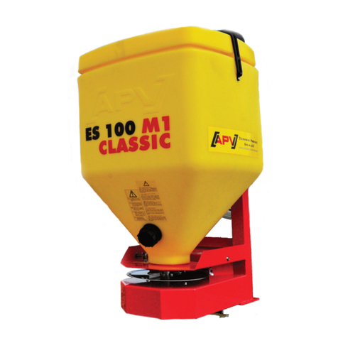
APV ES 100 M2 Special User manual

Original operating instructions
ES 100 M2 Special
Read this carefully before operating!
Version: 02/2015, V1.4
Order no.: 00600-3-137

2
Quality for Professionals
It should NOT be
an inconvenience or a luxury to read and comply
with the operating instructions; you cannot
simply experience from others that something is
a good product, then make the purchase and
assume everything will be self explanatory.
Those who go down this route not only inflict
damage on their own property, but make the
mistake of attributing the cause of any failure
to the machine, and not to themselves. In order
to be sure of success you must get into the
spirit of the thing, by learning about the
purpose of each individual device on the
machine and by gaining experience in how to use
it. Only then will you be satisfied both with
the machine and with yourself. These operating
instructions are intended to help you achieve
this.
Leipzig-Plagwitz 1872

3
Quality for Professionals
Professionals
Table of contents
1 EC Declaration of Conformity ................................................................................................................. 4
2 Provisions ............................................................................................................................................... 5
3 Guarantee ............................................................................................................................................... 5
4 Accident prevention ................................................................................................................................ 5
5 Basic nformation .................................................................................................................................... 5
5.1 Design and mode of operation ........................................................................................................ 5
5.2 Attaching to the tractor .................................................................................................................... 6
5.3 Mounting on an attachment ............................................................................................................ 6
5.4 Fastening the control module .......................................................................................................... 6
5.5 Electrical connections ..................................................................................................................... 7
5.6 Emptying and removing the tank .................................................................................................... 7
5.7 Control module ................................................................................................................................ 8
5.8 Slider sensor (available as an accessory) ...................................................................................... 9
6 Main display .......................................................................................................................................... 10
6.1 Working in the field ....................................................................................................................... 11
6.2 Surface area calculation ............................................................................................................... 11
6.3 Seed rate calibration test .............................................................................................................. 11
6.4 Emptying ....................................................................................................................................... 12
6.5 Day counter ................................................................................................................................... 12
6.6 Surface area ................................................................................................................................. 12
6.7 Operating hours ............................................................................................................................ 13
6.8 Operating voltage .......................................................................................................................... 13
6.9 Motor1 ........................................................................................................................................... 13
6.10 Language selection ................................................................................................................... 13
7 Settings................................................................................................................................................. 15
7.1 Spread width ................................................................................................................................. 15
7.2 Regulating the application rate ..................................................................................................... 15
7.3 Agitator .......................................................................................................................................... 16
7.4 Contact point adjustment .............................................................................................................. 17
7.5 Spreader disc, lateral distribution, spreader vanes ....................................................................... 17
8 Setting charts ........................................................................................................................................ 18
9 Controller messages ............................................................................................................................. 24
9.1 Notes ............................................................................................................................................. 24
9.2 Fault(s) .......................................................................................................................................... 24
10 Maintenance and care .......................................................................................................................... 25
10.1 General instructions .................................................................................................................. 25
10.2 Location of the type plate .......................................................................................................... 25
11 Technical data ...................................................................................................................................... 26
12 My idea ................................................................................................................................................. 27
13 Safety instructions ................................................................................................................................ 28
13.1 Intended use ............................................................................................................................. 28
13.2 General safety instructions and accident-prevention regulations ............................................. 29
13.3 Attached devices ...................................................................................................................... 30
13.4 Maintenance ............................................................................................................................. 31
14 Safety signs .......................................................................................................................................... 32
15 Accessories .......................................................................................................................................... 34
15.1 MX chassis hoist sensor (Art. No.: 00410-2-008) ..................................................................... 34
15.2 MX upper linkage hoist sensor (Art. No.: 00410-2-074) ........................................................... 35
15.3 Amphenol Molex sensor (item no.: 00410-2-006) ..................................................................... 36
15.4 Vehicle cable kit ........................................................................................................................ 37
15.5 Tractor cable kit ........................................................................................................................ 37
15.6 Extension cable 5m (4-pin) ....................................................................................................... 37
15.7 Quad bracket ............................................................................................................................ 37
15.8 Trailer/truck bed mounting bracket ........................................................................................... 38
15.9 Precision spreader plate ........................................................................................................... 38
15.10 Calibration bin ........................................................................................................................... 38
16 Notes .................................................................................................................................................... 39
4
Quality for Professionals
1 EC Declaration of Conformity
in accordance with Directive 2006/42/EC
The manufacturer APV Technische Produkte Ges.m.b.H.
Dallein 15, 3753 Hötzelsdorf, Austria hereby declares that the
"ES 100 M2 Special"
Universal Spreader
with digital and speed-controlled module,
Machine type designation / Product no. (see delivery declaration and title page)
to which this declaration of conformity refers, complies with all relevant basic health
and safety requirements specified in the EC Directive 2006/42/EC as well as with the
requirements specified in the other relevant EC directives
2006/42/EC
If applicable: title / number / version of other EC directives
.
To properly implement the health and safety requirements in the EC directives,
the following standards and/or technical specifications were
referenced:
EN 12100/1; EN 12100/2
If applicable: title / number / version
Your contact on CE matters at APV is Ing. Jürgen Schöls.
He can be reached by telephone at +43 (0) 2913-8001.
Dallein, 02/2015
Location, date
Signature
Ing. Jürgen Schöls
Managing Director

5
Quality for Professionals
Professionals
2 Provisions
Dear customer!
Congratulations! We are pleased you have purchased our product and wish you
much enjoyment and success working with it!
Please read all instructions contained in these operating instructions before using the
device!
3 Guarantee
On acceptance, please immediately check for any damage incurred to the device
during transport. Claims made for transport-related damage at a later date cannot be
accepted.
We provide a one year factory warranty from the date of delivery (your invoice or
delivery note serves as the warranty card).
This guarantee is limited to faults in material or design/construction and does not
extend to parts that are damaged by normal or excessive wear and tear.
The guarantee is voided if:
−the damage is caused by external forces
−operator error is at issue
−the stipulated requirements are not fulfilled
−the device is modified, augmented, or fitted with third-party spares without our
consent
−the device is cleaned with water
−the spreader is used during winter operations.
4 Accident prevention
The generally applicable accident prevention regulations of the respective country in
which the device is used must be observed.
The device may only be used by persons who have been informed of the possible
dangers.
5 Basic Information
5.1 Design and mode of operation
The “ES 100 M2 Special” universal spreader is a small seed spreader with a 100 litre
capacity.
The spreading disc is driven by a 12 V electric motor regulated by the controller. The
speed of the spreader disc, and therefore the working width, can easily be regulated
with the controller from the driver's seat. The power supply of the control module can
be established either via the three-pin standard socket or directly using a battery.

6
Quality for Professionals
5.2 Attaching to the tractor
For the type of attachment shown on the
left, screw the tractor drawbar between your
ES 100 M2 Special and the supplied
counter plate. You should use bolts with a
diameter of 10mm. Screw the top link
bracket to the top link plate and fix your
tractor's top link in place with the bolt.
5.3 Mounting on an attachment
When fitting the ES 100 M2
Special to an attachment, it is
best to use the counter plate. Use
this to secure your scattering unit
to a frame on the attachment.
Please ensure that the machine is
mounted at a height of approx.
one metre.
5.4 Fastening the control module
Using two screws, fasten the standard holder
(provided in the scope of delivery) in the cab. Store
excess cable in the driver's cab to avoid clamping
it.
Tip: Pay attention to the angle at which you view
the module to ensure optimum readability of the
display. You might have to bend the mount slightly
to set the correct angle.
Fig.: 3
Fig.: 1
Fig.: 2
Fig.: 4

7
Quality for Professionals
Professionals
5.5 Electrical connections
You can connect the cable supplied as standard directly to the three-pin standard
socket in the cab. Connect the other end to the control module.
The four-pin cable on the spreader is also connected to the control module.
The (20A) fuse is on the right side of the control module.
TIP: If your tractor or pulling vehicle does not have a three-pin standard socket, then
you must implement the wiring to the battery yourself. To do so you require a cable,
(vehicle cable kit, Art.No.: 00410-2-027, or tractor cable kit, Art.No.: 00410-2-022),
which can be obtained from us as an accessory.
Install the wiring as follows:
Connect the plug on the supplied standard cable with the connector on the adapter
cable. Then connect the two brown cables to the positive terminal of the battery. The
cable with a large cross section is fused to 30A and the thin cable to 5A. Lastly the
blue cable, which is fused to 30A, must be connected to the battery's negative
terminal.
CAUTION: Failure to comply with these instructions can result in damage to the
control module!
IMPORTANT: After using the implement, the controller should be disconnected (for
safety reasons).
5.6 Emptying and removing the tank
To empty the tank, unscrew the screw plug on
the discharge nozzle at the front of the tank
and hold a container, bag or other receptacle
under it. To ensure that the machine is
emptied completely, turn the device upside
down.
In rare cases, it will be necessary to remove
the plastic tank for cleaning. To do this, bend
the latches inwards with a small screwdriver
and pull the tank up and away.
Before putting the tank back in place, bend
the latches out again and then replace the
tank. Finally, seal the cone with silicone again
to prevent water ingress.
Fig.: 5

8
Quality for Professionals
5.7 Control module
The ES 100 M2 Special has a control module with a hermetically sealed membrane
keyboard. There is a three-pin standard plug on the base, the same as the one in the
tractor cabin. This is used for the power supply. There is also a four-pin plug for the
connection to the spreader, as well as a twelve-pin plug for the sensors.
Furthermore, on the right-hand side you will find the fuse (20A).
The “On/Off” button used to switch the implement on and off is at the
bottom left.
These buttons can be used to adjust the spreader disc's speed
precisely.
This opens and closes the shutter.
Pressing the
button switches the controller on; the control lamp above the button
begins to light up.
Using the buttons, you can now control the spreader disc's speed as
desired.
If you now want to drive off and start spreading, open the shutter with the button;
the "Shutter open" indicator light above the button lights up.
The material to be spread now trickles onto the spreader disc and is spread in
accordance with the speed.
When you come to a stop, press the button (the “Shutter closed” indicator light
above the button lights up); the shutter closes.
It is only expedient to also switch off the motor when you leave the field.
Fig.: 6
Digital display
Lights up when switched
on switched on
On/Off button
Cursor "down"
Cursor "up"
Reduce speed of
spreader plate
ncrease speed of
spreader plate
Lights up when the
slide valve is open
Open shutter
Lights up when Close
the slide valve slide valve
is closed

9
Quality for Professionals
Professionals
5.8 Slider sensor (available as an accessory)
The servo motor shutter opens and closes automatically via the sensor when an
implement is lifted and lowered.
The sensor is connected at the 12-pin connector on the control module. The control
module detects the sensor automatically and opens/closes the servo motor shutter
via the sensor, as soon as the sensor has been connected.
TIP: The shutter can also be opened and closed manually (by pressing the
buttons).
For coupled tillage implements, the sensor can be installed on the chassis, because
the hoist is not being used.
In order to rotate the working position, the button and button must be
pressed at the same time.
This appears on the display:
Because most tillage machines are lifted and
lowered when in use, one option is to install
the sensor at or on the lever arm (see Fig.: 7
or 13) of the tractor.
TIP: The sensor can also be secured elsewhere as long as there is a mechanical
movement of more than 50 mm.
The distance between the sensor and the magnet should not exceed 2 cm.
Note: The slider only opens when the spreading disc is running!
Fig.: 7
T
hree
-
step signal
inverted!

10
Quality for Professionals
3.5 V3.16
www.APV.at
Speed: 1,000
6 Main display
Power-up message: Shown during the
switch-on procedure. Displays the
device types and versions.
The software version can be very helpful for customer service or when servicing.
Set motor speed in rpm
After the device has been switched on, you can navigate through the menu using the
following three buttons:
The cursor buttons are used in the menu to move
one menu item up or down.
The following menu items are available:
Use to select a menu item then confirm the selection with .
Here, using again, you can select a submenu (if available) and confirm the
selection with ; this opens the value setting mode.
Values can be set using the buttons.
Always confirm the set value with .
Note: If no further settings are made, the display returns to the main screen.
Area
calculation
Seed rate calibration
test Emptying
Day counter Surface area:
Operating h
ours:
576.23
Operating voltage:
12.7 V
Motor1:
11.5A
Select language?

11
Quality for Professionals
Professionals
Speed: 1000
Working width?
12.0m
Speed?
10km/h
Surface area calculation
reset? OK
Seed rate calibration
test
Speed:
6.1 Working in the field
If you want to interrupt spreading for a longer period of time, press the button to
switch off the spreader. Pressing the button again to re-start the machine brings
you directly back to the main menu. The following menu will then be immediately
displayed:
The spreader disc starts turning (at the last set
speed), and the actual speed shows in the display.
The buttons can be used to adjust the motor to
the desired speed in accordance with the desired spreading width.
6.2 Surface area calculation
This is an additional function with which, before you begin spreading, you must input
the correct parameters, e.g. the spreading width and the drive speed at which, per
the tachometer, you will drive. These parameters are also required when doing a
seed rate calibration test with your ES 100 M2 Special.
Press and using the buttons select the
desired value.
Pressing here resets the hectare counter to zero.
6.3 Seed rate calibration test
Go to the menu item "seed rate calibration test" and
set the following values:
The buttons are used to make the respective settings.
If you want to change a value, select it with the button and change the value with
the buttons. Confirm the value with the button.
The speed must be input here.
TIP: Refer to the setting charts for the respective values (item 8).

12
Quality for Professionals
Emptying
Start test?
Surface area:
25 ha
Operating hours:
0.00h
Reset?
Surface area:
25 ha
Pressing the button starts the seed rate calibration
test.
Note: The seed rate calibration test runs for 1 minute. To be able to actually spread
the desired application rate, we recommend repeating the seed rate calibration test
until the values (kg/min.) have levelled off or until the differences are no longer
excessive.
The slider only opens when the spreading disc is running!
6.4 Emptying
Confirming with the button starts the emptying
process; the spreader disc starts turning and the
shutter opens automatically.
TIP: To empty quickly, open the metering shutter completely.
Emptying can be stopped at any time with the buttons.
6.5 Day counter
The surface area and operating hours applicable since the last reset are displayed
here.
Displays the sown area.
Displays the operating hours.
Pressing here resets the surface area and
operating hours to zero.
6.6 Surface area
The total sown area is displayed here.
Note: This cannot be set to zero.

13
Quality for Professionals
Professionals
Operating hours:
0.00h
Operating voltage:
12.7V
Select language?
Motor1: 0.0A
6.7 Operating hours
Displays the total operating hours.
Note: This cannot be set to zero.
6.8 Operating voltage
Displays the current operating voltage.
6.9 Motor1
Displays the spreader plate motor's power consumption
in amperes.
6.10 Language selection
Confirm with and, using the buttons, select
the desired language and confirm the selection with the
button.

14
Quality for Professionals
Control module 3.5 (language selection)
Beginning with software version V3.16, the following languages can be
selected:
•German (Deutsch)
•English
•
French (Français)
•
Czech (Česky)
•Dutch (Nederlands)
•Danish (Dansk)
•Hungarian (Magyar)
•Polish (Polski)

15
Quality for Professionals
Professionals
7 Settings
7.1 Spread width
The spread width depends on the density and shape of the seed and the spreader
disc speed. The seed spreader is designed to spread seed evenly over an area of 24
m. For this to be successful, the battery and generator must be in good condition.
Please refer to the setting charts under item 12 for the precise settings for sowing
rate, working width, etc. We recommend attaching the spreader at least 1 m above
the ground to enable an optimal spreading density.
Note: If the ES 100 M2 Special is attached to a machine with a small working width
and the seed is to be scattered directly into/in front of the roller, the spreader can be
angled slightly downward when attached. However, please note that the tank only
empties completely if it is level!
7.2 Regulating the application rate
To regulate the seed rate, turn the metering handle
that is attached on the left side. This moves the
pointer on the metering slide valve, which is used to
set the required position on the scale. The metering
slide valve is then fastened in position with the lock
nut attached to the thread.
Position 0: Closed; Position 10: Completely open.
Refer to the respective setting chart for the settings
you require. The transport box or a bag placed over
the front of the spreader can be used to perform the seed rate calibration test. If the
box is used, one of the sides is cut out and inserted in the spreader. Then, using the
control module, set the approximate spreader disc speed with which you intend to
spread seed on the field and select the required value for the metering shutter on the
scale. Selecting the right speed is important because the calibration quantity also
depends on the speed!
Using the “Open shutter” button on the control module, the seed rate calibration test
is now executed by opening the shutter for precisely one minute while catching the
spreading material so that none is wasted.
Fig.: 8

16
Quality for Professionals
The following formula is used to calculate the sowing rate:
[kg/min]Weight
600
[m]dthScatter wix[km/h]speedDrivingx[kg/ha]umeoutput volDesired =
Example:
•The calibrated and collected spreading material must now be weighed.
•By changing the value on the metering shutter's scale and repeating the
calibration, the correct value can then be determined.
•This process must be repeated until the desired output has been reached.
•Once work has begun, you should field check the sowing rate. In particular,
the drive speed, the application rate and the surface area distribution must be
checked.
7.3 Agitator
Because an agitator drive with two expansion pins, as a
rule, is not required, the agitator was equipped in the
factory with only one agitator pin. However, if you need
more agitating power (e.g. for grass, etc.), proceed as
follows: Connect the standard expansion pins (provided
in the scope of delivery) to the agitator's lower expansion
pin. This increases the agitator's efficiency. If necessary,
the top agitator pin, included together with the expansion
pins in a reclosable bag, can be secured to the opening
specified on the agitator.
This ensures the continued flow of the spread material
which is either very light (grasses, etc.) or tends to form bridges (slightly damp seed,
etc.).
[kg/min] 1,2
600
[m] 12[km/h] 12[kg/ha] 5 =
×
×
Fig.: 9

17
Quality for Professionals
Professionals
7.4 Contact point adjustment
Using the contact point adjustment, you can adjust the
overall scatter distribution by 20° in both directions.
This can be important for many scatter materials, for
example, to save you adjusting the throw blades. For
instance, if the scatter distribution is rotated 15° to the
right, then set the contact point adjustment 15° to the
left. By turning it further to the right, you can also
achieve a fenceline scattering function.
7.5 Spreader disc, lateral distribution, spreader vanes
The spreader disc must run anticlockwise. The spreader vanes fastened to the
spreader disc allow the spread pattern to be adjusted to the specific weight (density)
of the material to be spread. This results in a uniform lateral distribution. The three
throw blades are normally set to -1, -2 and -3. If the lateral distribution is not ideal, for
some spread widths and
spread material, adjust the spreader vanes as follows:
If the spreader vanes are in the front position, the material to be spread exits the
spreader disc somewhat later and is thrown slightly more to the right (as seen when
looking at the spreader from the front). If the spreader vanes are positioned to the
rear, the material to be spread exits the spreader disc somewhat earlier and is
thrown slightly more to the left (as seen when looking at the spreader from the front).
Note: The slider only opens when the spreading disc is running!
Fig.: 10
Fig.: 11

18
Quality for Professionals
8 Setting charts
Gras
Grass
Herbe
Lolium perenne
(with spring pins fitted
underneath)
Speed (working width)
Slide valve position
3
5
8
10
350 (1
-
2m)
0,13 0,38 1,23 1,48
1600 (~ 4m)
0,65 1,72 3,05 3,34
2800 (~ 6m)
0,84 1,82 2,88 3,2
3000 (~ 7m)
0,85 1,86 2,89 3,22
Weight in kg/min
Senf
Mustard
Moutarde
Sinapis Alba
Speed (working width)
Slide valve position
3
5
8
10
35
0 (1
-
2m)
0,84 1,82 3,25 3,39
16
00 (~ 7m)
1,19 2,53 4,21 4,53
2800 (~ 14m)
1,18 2,56 4,18 4,49
3000 (~ 17m)
1,25 2,67 4,44 4,74
Weight in kg/min
Weißklee
White clover
Trèfle Blanc
Trifolium repens
Speed (working width)
Slide valve position
1
3
5
8
10
350 (1 - 2m) 0,02 1,39 2,91 5,27 5,77
16
00 (~ 7m)
0,08 2 3,79 6,09 6,66
2800 (~ 14m)
0,11 1,83 3,72 6,09 6,5
3000 (~ 16m)
0,12 1,97 3,99 6,31 6,97
Weight in kg/min

19
Quality for Professionals
Professionals
Blaue Lupine
Blue Lupine
Lupin Bleu
Lupinus angustifolius
Speed (working width)
Slide valve position
3
5
8
10
35
0
(2
-
3m)
0,24 0,63 1,45 1,47
16
00 (~ 10m)
0,68 1,59 2,73 2,88
2800 (~ 20m)
0,72 1,55 2,77 2,83
3000 (~21m)
0,77 1,69 2,87 3,05
Weight in kg/min
Rettich
Radish
Radis
Raphanus
raphanistrum
Speed (working width) Slide valve position
3
5
8
10
35
0
(1
-
2m)
0,49 1,29 2,29 2,02
16
00 (~ 7m)
0,89 1,92 3,31 2,51
2800 (~ 14m)
0,89 1,97 3,26 2,68
3000 (~ 17m)
0,96 2,06 3,61 2,84
Weight in k
g/min
Phacelia
Phacelia
Phacélie
Phacelia tanacetifolia
Speed (working width) Slide valve position
3 5 8 10
350 (1 - 2m) 1,1 2,3 3,43 3,56
1600 (~ 5m) 1,43 3,02 4,47 4,45
2800 (~ 10m) 1,4 2,99 4,15 4,44
3000 (~ 12m) 1,47 2,73 4,56 4,65
Weight in kg/min

20
Quality for Professionals
Buchweizen
Buckwheat
Blé Noir
Fagopyrum
Speed (working width)
Slide valve position
3
5
8
10
35
0 (1
-
2m)
0,39 1,4 2,69 2,99
16
00 (~ 12m)
0,79 2,19 3,72 3,49
2800 (~ 1
5m)
0,81 2,23 3,58 3,97
3000 (~ 17m)
0,9 2,35 3,94 4,33
Weight in kg/min
Wicke
Vetch
Vesce
Vicia
Speed (working width)
Slide valve position
3
5
8
10
35
0 (1
-
2m)
0,53 1,81 3,14 3,44
16
00 (~ 14m)
1,05 2,85 4,27 3,93
2800 (
~ 17m)
1,13 2,87 4,31 4,37
3000 (~ 18m)
1,15 3,62 4,48 4,77
Weight in kg/min
Rotklee
Red Clover
Trèfle Rouge
Trifolium
Speed (working width)
Slide valve position
3
5
8
10
35
0 (1
-
2m)
1,29 3,08 5,55 5,93
16
00 (~ 9m)
1,53 3,57 6,44 7,03
2800 (~15m)
1,65 3,82 6,53 6,93
3000 (~16m)
1,79 4,23 6,55 7,15
Weight in kg/min
Table of contents
Other APV Farm Equipment manuals

APV
APV Tined Weeder Pro VS 600 M1 User manual

APV
APV GRASSLAND PRO HARROW GP 600 M2 User manual

APV
APV PS500M2 User manual

APV
APV AS 300 M1 User manual

APV
APV GK 400 M1 User manual

APV
APV AS 300 M1 User manual

APV
APV GP 600 M1 Installation instructions

APV
APV PS 800 M1 Operational manual

APV
APV Grassland harrow GS 300 M1 Operational manual

APV
APV ES 100 M3 EVO Installation instructions

APV
APV Tined Weeder Pro VS 600 M1 User manual

APV
APV RH 600 M1 User manual

APV
APV ZS 200 M4 User manual

APV
APV LF 600 M1 User manual

APV
APV RH 600 M1 User manual

APV
APV ES 100 M1 Classic Installation instructions

APV
APV PS 300 M1 D User manual

APV
APV GW 400 M1 User manual

APV
APV PS 120 M1 User manual

APV
APV AS 600 M1 User manual